Technical Reference · UAV-DRONE
UAV Lightweight Micro-Coax
Custom Micro-Coax Cable Assemblies for UAV and Drone Programs
For aerial camera systems, FPV links, and lightweight routes that need stable shielding and motion-aware fit
EDPcable supports custom micro-coax cable assemblies for UAV, drone, FPV, airborne camera modules, gimbal systems, and other products where weight, route stability, and shielding behavior all matter to the final build. The challenge is not getting one sample built. It is making sure connector family, wire gauge, route path, motion conditions, and version scope stay aligned under one released definition.
Quick Links
QUICK ACCESSStart with the sections closest to the project structure, interface requirements, and validation scope.
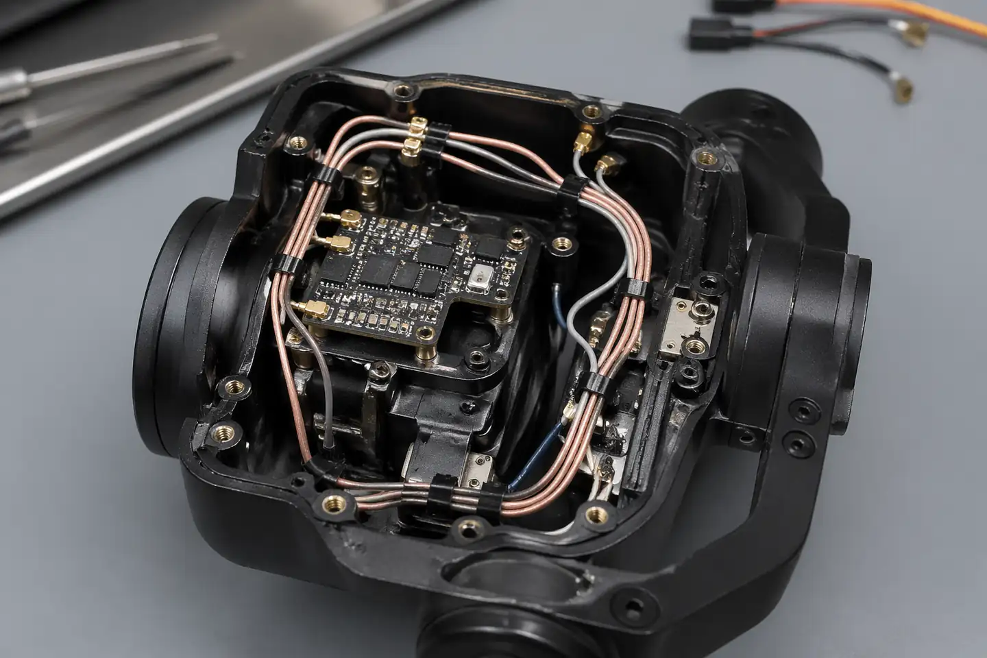
UAV Micro-Coax Product Overview
UAV micro-coax programs work best when the aerial-device context is already clear and the next review can focus on weight, route stability, shielding, motion conditions, and version scope before sampling.
| NO | Item | Typical Range or Meaning |
|---|---|---|
| 01 | Common Use | FPV links, airborne cameras, gimbal modules, lightweight vision systems |
| 02 | Key Inputs | Connector family, wire gauge, route path, shielding notes, motion limits, version scope |
| 03 | Engineering Focus | Weight control, route stability, motion-aware path fit, shielding behavior |
| 04 | Quality Focus | Stable termination, repeatable routing, version-linked records |
| 05 | Release Basis | Connector references, route notes, motion conditions, and released file correspondence |
Customer Pain Points
UAV micro-coax projects often sound straightforward once the product or route category is known. In real RFQ and sample work, delays usually appear in route fit, structure judgement, and revision control rather than in the label alone.
| NO | Customer Pain Point | Typical Risk | What Needs Early Confirmation |
|---|---|---|---|
| 01 | Product design issues | The connector path, structure, or local fit still does not truly match the UAV micro-coax build, so the sample becomes only a temporary reference | Connector references, route path, structure boundaries, and installation space |
| 02 | Product quality issues | Execution, local fit, or batch consistency drifts across repeated UAV micro-coax builds | Structure definition, quality focus, and revision linkage |
| 03 | Lead-time issues | Missing inputs force repeated sample loops and slow quotation, release, and batch timing | Connector data, route notes, project stage, quantity, and timing |
| 04 | After-sales issues | It becomes difficult to tell whether the issue came from structure, revision, or installed conditions | Drawing files, sample approval records, batch labels, and shipment records |
| 05 | Complaint-handling issues | Revision boundaries are unclear, so issue tracing stays slow | Revision confirmation, batch correspondence, and inspection records |
| 06 | Pricing issues | A broad request turns into repeated pricing changes once real fit constraints surface | Structure complexity, material expectations, quantity, and delivery boundaries |
Product Applications
This route is not only a category label. In practice, UAV micro-coax work usually appears in device programs where fit, route logic, and revision scope all matter. The scenes below are the most common application contexts.
| NO | Application Scene | Scene Focus | Typical Concerns |
|---|---|---|---|
| 01 | FPV links | lightweight routing with stable signal behaviour | wire gauge, shielding notes, and route stability |
| 02 | Airborne camera modules | compact route fit around camera-side structure | connector matching, local clearance, and version boundaries |
| 03 | Gimbal systems | motion-aware routing through moving sections | bend behaviour, retention points, and repeat handling |
| 04 | Inspection or mapping drones | repeatable lightweight harness execution across batch builds | delivery timing, file correspondence, and issue tracing |
| 05 | Replacement and upgrade programs | matching old aerial routes to the active platform | usable scope, released basis, and after-sales support |
Application Scene Visuals
IMAGES · 05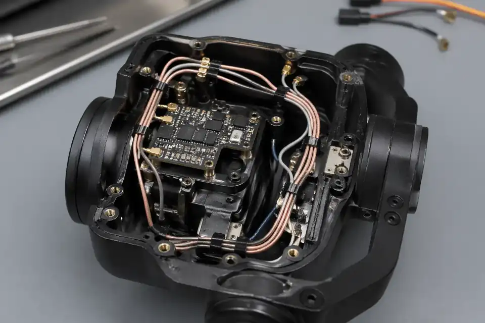
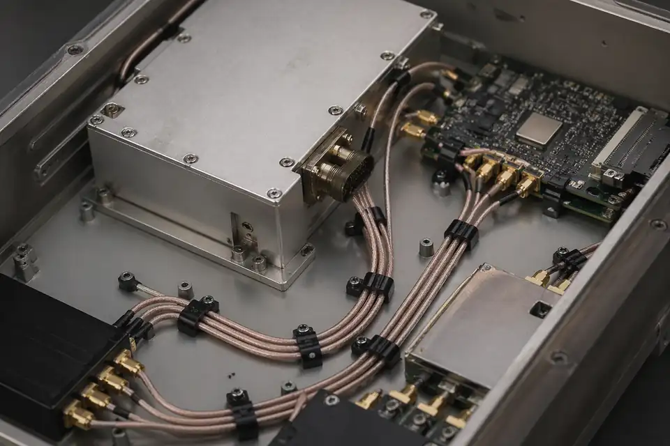
Micro-coaxial harness routed through a UAV flight-control interconnect
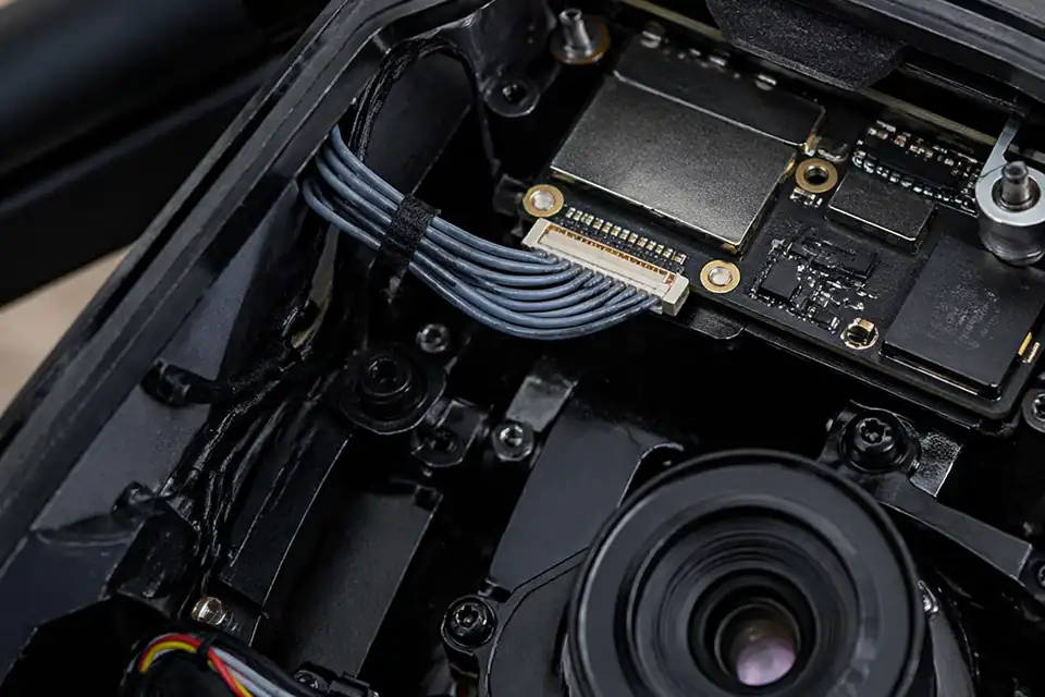
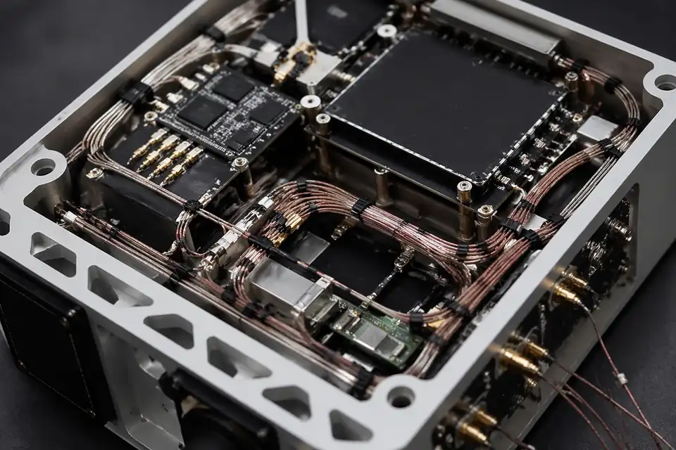
Micro-coaxial harness inside an airborne imaging module
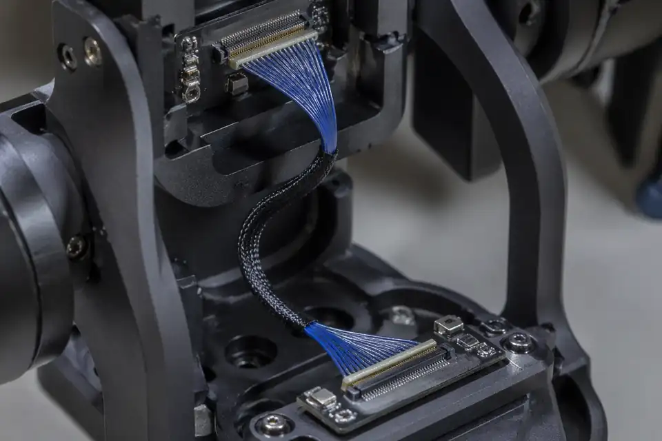
Micro-coaxial harness inside a gimbal signal interconnect with repeated-motion bend zone
Micro-coaxial harness inside a telemetry or communications module in an unmanned system
Micro-coaxial harness inside a lightweight unmanned electronics module
UAV and Gimbal Micro-Coax Design Matrix
UAV harness decisions are dominated by moving geometry, mass distribution, vibration, retention, and the named camera or radio interface. Flight-platform validation cannot be inferred from a connector catalog.
| NO | Design Variable | Project Input | Release Evidence |
|---|---|---|---|
| 01 | Payload interface | Camera, gimbal, antenna, sensor, or control endpoint | Named endpoint map |
| 02 | Connector pair | Exact board and cable-side references | Manufacturer mating documents |
| 03 | Cable bundle | Coax count, wire size, shields, and auxiliary circuits | Construction drawing |
| 04 | Motion axes | Pan, tilt, roll, travel angle, and home position | Motion-envelope model |
| 05 | Mass target | Harness and connector allocation within payload budget | Approved measured mass |
| 06 | Retention | Fixing points, service loop, clamps, and connector support | Installed routing detail |
| 07 | Environment | Vibration, temperature, contamination, and altitude inputs | Platform qualification matrix |
| 08 | Electrical target | Protocol, impedance, loss, power, and grounding needs | Channel and power budget |
First-Party Engineering References
- Hirose DF36 micro-coax connector series
Lists drone and camera uses plus exact pitch, positions, wire range, geometry, and ratings by series.
UAV Route and Motion Failure Modes
A bench-functional cable can still fail when the gimbal sweeps, vibration shifts a service loop, or the connector exit carries payload loads. Failure review follows the installed motion path.
| NO | Failure Mode | Installed Cause | Design Control |
|---|---|---|---|
| 01 | Gimbal torque increase | Harness stiffness or service loop resists motion | Measure torque with routed assembly |
| 02 | Intermittent video | Repeated bending concentrates at connector exit | Move flex zone and support termination |
| 03 | Chafing | Bundle contacts frame edge through full travel | Add clearance, retention, or protection |
| 04 | Connector back-out | Vibration loads an unsupported mating pair | Confirm lock and local strain relief |
| 05 | EMI or link margin loss | Route moves close to motors or power switching | Validate worst-position channel behavior |
| 06 | Variant mismatch | Camera or gimbal revision changes endpoint mapping | Control payload applicability by revision |
UAV Harness Verification Plan
Verification separates assembly workmanship from platform qualification. The sample plan uses the actual route, motion range, retention hardware, and representative electronic endpoints whenever available.
| NO | Verification | Condition | Recorded Result |
|---|---|---|---|
| 01 | Netlist | Continuity and short check against payload mapping | Per-assembly electrical result |
| 02 | Mass | Weigh released harness including retention parts | Measured sample mass |
| 03 | Motion clearance | Sweep all defined gimbal axes and extremes | Route and interference record |
| 04 | Dynamic continuity | Monitor selected circuits during agreed motion cycles | Cycle condition and fault log |
| 05 | Vibration | Customer-defined platform profile with installed retention | Qualification result |
| 06 | Link performance | Worst-route camera or radio system test | Platform channel evidence |
| 07 | Post-test inspection | Inspect exits, jackets, shields, and locks | Before-and-after condition record |
Engineering Capability
Engineering value in a UAV micro-coax page comes from tying route fit and structure judgement together before release. Cross-family engineering review, drawing control, and documentation practice are covered in the Related Capability Pages below.
Engineering Capability
Review route path, connector references, and local fit together for the UAV micro-coax build.
Quality and Verification Highlights
Watch local-fit zones, connector exits, and route transitions specific to UAV micro-coax installs.
Evidence Chain
Controlled wire-gauge and route drawing
Keep connector references, wire gauge, route, shielding requirements, motion boundary, and active UAV revision on one released drawing basis so samples and production do not drift apart.
Motion and installed-fit review
Record the project vibration profile, bend zones, retention, local clearance, and route cycle expectations so the sample is evaluated against the intended UAV platform conditions.
Sample and batch correspondence
Tie sample approval, agreed motion or electrical results, batch labels, and shipment records to the same UAV revision so later platform changes and flight validation remain controlled.
Files and Batch Support
UAV micro-coax work has its own document layer around route and fitting boundaries. Cross-family file control, batch traceability, and certification practice are summarised in the Related Capability Pages.
UAV micro-coax route and fitting-boundary records
Capture the route path, local fit, and installation-space limits that are specific to the UAV micro-coax build so later structural differences can be traced back to the right layer of change.
Certifications / Records Visuals
IMAGES · 04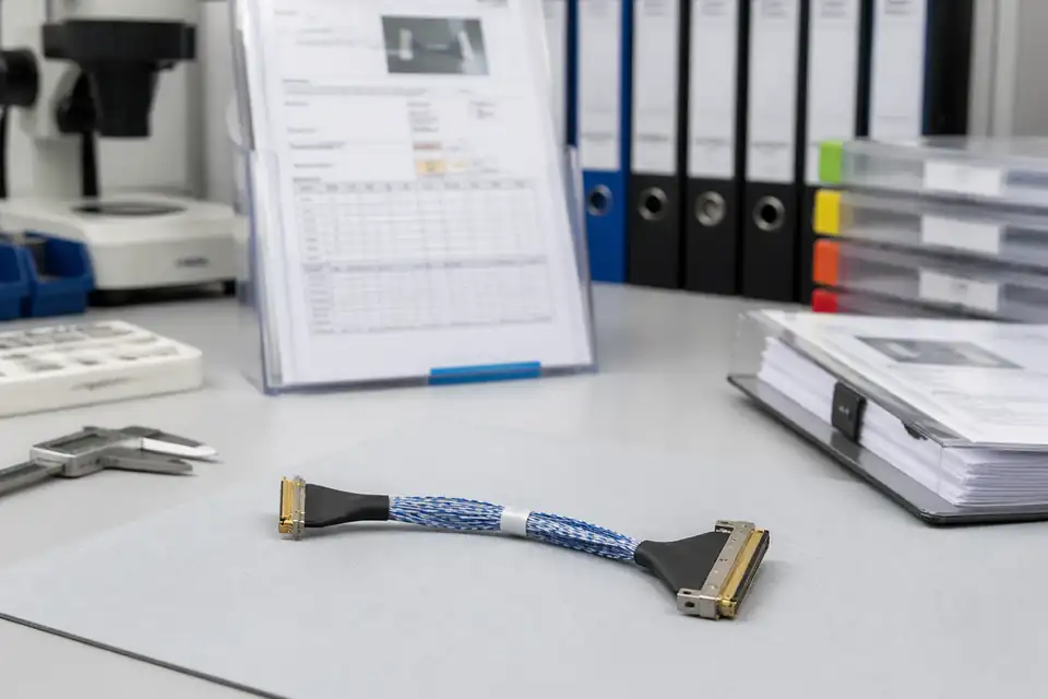
Micro-coaxial assembly document-control scene with records and labels secondary to the harness
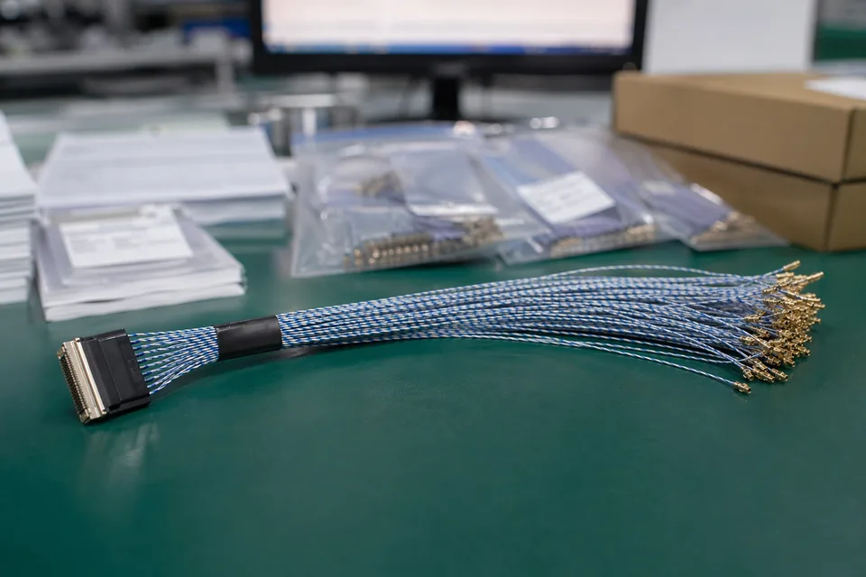
Micro-coaxial controlled record scene with compact harness sample foreground and document support
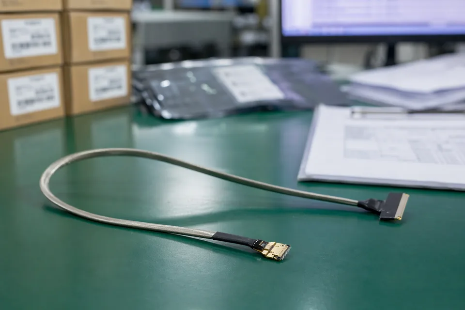
Micro-coaxial batch traceability archive with fine connector lot labels and cable sample visible
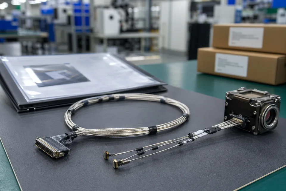
Micro-coaxial released-sample approval folder beside shielded harness and compact module mockup
FAQ
Can you work from an old UAV micro-coax sample?
Yes. Old parts help, but weight limits, route fit, motion conditions, and the current platform version still need to be checked before the sample can represent the released build.
What is the minimum input for a UAV micro-coax quotation?
Send connector references, wire-gauge notes, route context, motion conditions, project stage, and expected quantity.
Why do UAV micro-coax programs need more than a connector reference?
Because weight limits, route geometry, shielding logic, and motion boundaries often decide whether the build can actually be released cleanly.
Can one UAV micro-coax assembly cover several versions?
Sometimes, but only if route geometry, weight boundaries, and version scope stay inside the same approved definition.
Can review start before the full drawing package is complete?
Yes. Early review can start from connector references, route context, and current structure limits, then tighten as the file package becomes clearer.