Technical Reference · 0-25MM-PITCH
0.25mm Pitch Micro-Coax
0.25 mm Pitch Micro-Coax Harnesses for Dense Internal Routes
Select the exact connector geometry, mating pair, supported wire, contact map, and service clearance
A 0.25 mm contact pitch describes one connector dimension, not a complete or interchangeable harness. EDPcable releases the assembly from the exact series and part numbers, positions, supported micro-coax construction, mating direction, lock, pin and ground allocation, cable exit, first bend, route envelope, and device validation plan.
Quick Links
QUICK ACCESSStart with the sections closest to the project structure, interface requirements, and validation scope.
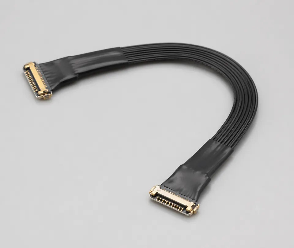
0.25 mm Series and Route Inputs
Use this page after the board and cable interfaces confirm a 0.25 mm-pitch system. Manufacturer examples show why the series still matters: CABLINE-UX II and CABLINE-CX II share pitch but differ in geometry and available configurations.
| NO | Release field | Project definition |
|---|---|---|
| 01 | Common Use | Dense display, camera, sensor, and compact internal links whose exact mating interface uses 0.25 mm pitch |
| 02 | Key Inputs | Complete plug and receptacle codes, suffixes, positions, cable construction, contact map, lock, mating direction, and revision scope |
| 03 | Engineering Focus | CABLINE-UX II is one 0.25 mm vertical-mating example; CABLINE-CX II is a distinct 0.25 mm horizontal-mating example |
| 04 | Quality Focus | Exact-series wire support, termination alignment, magnified inspection, controlled mating, first bend, and route clearance |
| 05 | Release Basis | Current manufacturer drawings, approved mating pair, released harness drawing, installed-fit sample, and project test plan |
Engineering Inputs
Use these items as first-round review inputs so the discussion does not rely on the page label alone.
Provide exact plug and receptacle codes, suffixes, positions, drawings, and current manufacturer mating references.
Provide supported micro-coax type and AWG, pin and ground map, shielding, termination, and electrical target.
Provide mating direction, mated height, cable exit, first bend, fixing, service access, and enclosure clearance.
State device revisions, sample, pilot, and production quantities, target dates, and substitution boundaries.
Define continuity, magnified termination, fit, retention, TDR or system-test method, limits, and report scope.
Customer Pain Points
0.25mm-pitch micro-coax projects often sound straightforward once the product or route category is known. In real RFQ and sample work, delays usually appear in route fit, structure judgement, and revision control rather than in the label alone.
| NO | Customer Pain Point | Typical Risk | What Needs Early Confirmation |
|---|---|---|---|
| 01 | Product design issues | The connector path, structure, or local fit still does not truly match the 0.25mm-pitch micro-coax build, so the sample becomes only a temporary reference | Connector references, route path, structure boundaries, and installation space |
| 02 | Product quality issues | Execution, local fit, or batch consistency drifts across repeated 0.25mm-pitch micro-coax builds | Structure definition, quality focus, and revision linkage |
| 03 | Lead-time issues | Missing inputs force repeated sample loops and slow quotation, release, and batch timing | Connector data, route notes, project stage, quantity, and timing |
| 04 | After-sales issues | It becomes difficult to tell whether the issue came from structure, revision, or installed conditions | Drawing files, sample approval records, batch labels, and shipment records |
| 05 | Complaint-handling issues | Revision boundaries are unclear, so issue tracing stays slow | Revision confirmation, batch correspondence, and inspection records |
| 06 | Pricing issues | A broad request turns into repeated pricing changes once real fit constraints surface | Structure complexity, material expectations, quantity, and delivery boundaries |
Product Applications
This route is not only a category label. In practice, 0.25mm-pitch micro-coax work usually appears in device programs where fit, route logic, and revision scope all matter. The scenes below are the most common application contexts.
| NO | Application Scene | Scene Focus | Typical Concerns |
|---|---|---|---|
| 01 | Dense display modules | fine-pitch connector control and compact route geometry | pitch fit, local clearance, and stable termination |
| 02 | Compact consumer devices | extreme-space routing inside thinner enclosures | wire gauge, first-turn behaviour, and fixing logic |
| 03 | High-density internal links | repeatable execution across tighter signal routes | connector matching, route stability, and revision scope |
| 04 | Small camera or sensor modules | miniaturized assembly under local-fit pressure | retention points, shielding notes, and batch consistency |
| 05 | Replacement and upgrade programs | matching historical fine-pitch builds to the active platform | released basis, usable boundaries, and traceable support |
Application Scene Visuals
IMAGES · 05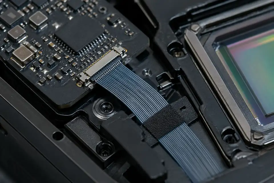
0.25mm-pitch micro-coaxial interconnect inside a high-density display module
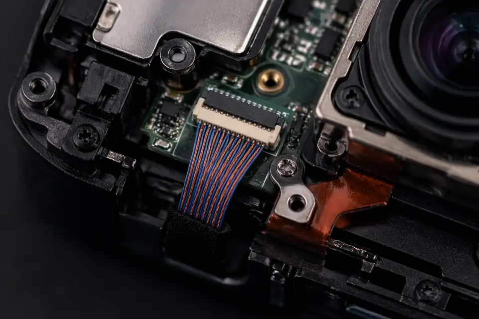
0.25mm-pitch micro-coaxial interconnect inside a compact camera or imaging module
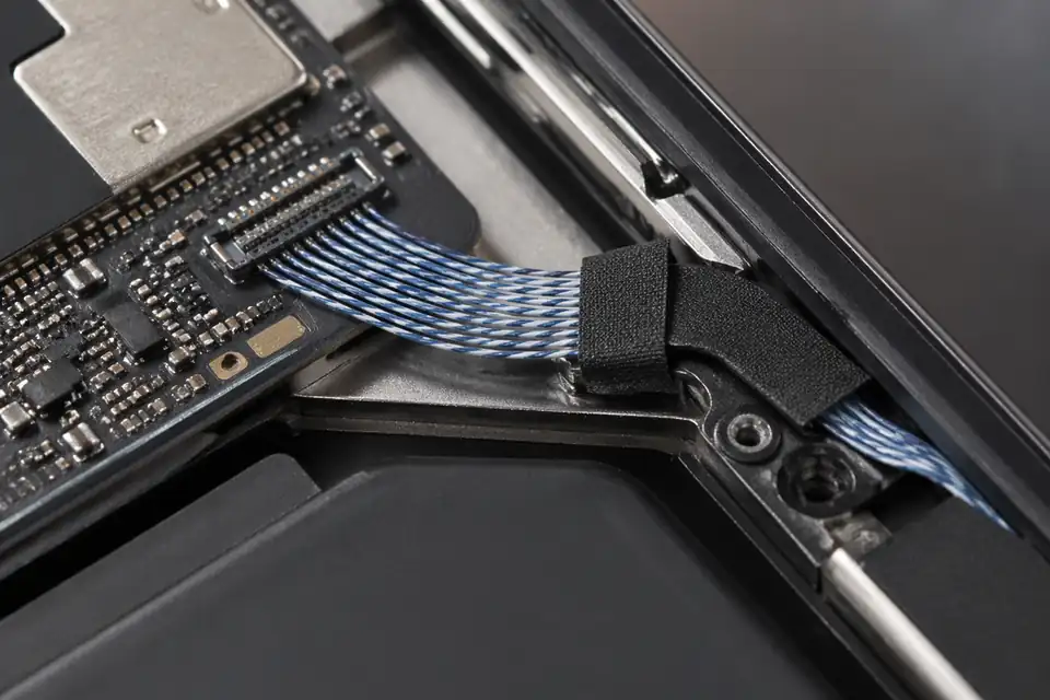
0.25mm-pitch micro-coaxial interconnect inside a thin portable electronics device
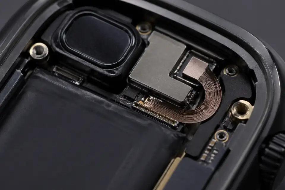
0.25mm-pitch micro-coaxial interconnect inside a wearable device
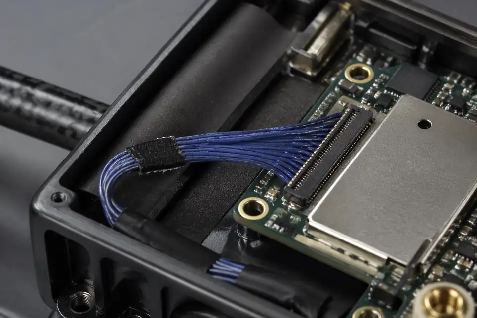
0.25mm-pitch micro-coaxial interconnect inside a small unmanned-system electronics module
0.25 mm Micro-Coax Interface Definition Matrix
A 0.25 mm contact pitch identifies a connector geometry, not a finished harness tolerance or cable diameter. Release starts from the exact plug, receptacle, wire range, mating direction, pin assignment, and installed route.
| NO | Design Variable | Project Definition | Release Evidence |
|---|---|---|---|
| 01 | Connector identity | Complete plug and receptacle part numbers | Matched manufacturer drawings |
| 02 | Contact pitch | 0.25 mm only for the named connector series | Series specification and exact P/N |
| 03 | Position count | Signal, ground, spare, and power contacts | Approved pin-assignment table |
| 04 | Cable construction | Micro-coax AWG and shield construction per terminal | Cable and terminal compatibility review |
| 05 | Mating direction | Horizontal or vertical insertion with access clearance | Installed section view |
| 06 | Ground architecture | Ground-contact allocation and shell termination points | Grounding schedule on drawing |
| 07 | Route envelope | Connector exit, first bend, fixing points, and service space | Device route overlay |
| 08 | Variant boundary | Approved connector suffixes and device revisions | Released applicability list |
First-Party Engineering References
- I-PEX CABLINE-UX II product data
First-party 0.25 mm vertical-mating example with published position and supported-wire options; values apply only to the selected UX II part.
- I-PEX CABLINE-CX II product data
First-party 0.25 mm horizontal-mating example; it remains a distinct series with exact-part conditions.
- I-PEX micro-coax and twinax connector matrix
Manufacturer comparison of series geometry, pitch, positions, and cable ranges; current exact-part documents govern release.
0.25 mm Interface Failure-Mode Review
At this density, near-match parts and handling errors can dominate before any channel measurement begins. The review isolates mating, termination, grounding, and route risks instead of treating pitch as the whole specification.
| NO | Failure Mode | Likely Cause | Prevention Boundary |
|---|---|---|---|
| 01 | Incomplete mating | Suffix, latch, or insertion direction mismatch | Use exact mating pair and insertion instruction |
| 02 | Terminal damage | Wire size outside the connector termination range | Approve cable-to-terminal compatibility before build |
| 03 | Intermittent contact | Connector loaded by an uncontrolled first bend | Define exit support and local strain relief |
| 04 | Crosstalk or return-path change | Signal and ground allocation altered during mapping | Lock the complete pin table and ground pattern |
| 05 | Assembly-version mix | Similar 0.25 mm variants share an informal name | Control suffix, drawing revision, and labels |
| 06 | Housing damage | Cable used to pull or unmate the connector | Specify handling tool and service access |
0.25 mm Assembly Verification Plan
Verification proves the released mating pair and route, not a generic 0.25 mm capability. Electrical checks are paired with magnified termination inspection and an installed-fit review.
| NO | Verification Item | Method and Condition | Acceptance Record |
|---|---|---|---|
| 01 | Part-number match | Compare plug, receptacle, and suffixes to BOM | Incoming identity record |
| 02 | Wire order | Test every conductor and required open in the released netlist for continuity and unintended connections | Netlist result by assembly |
| 03 | Termination condition | Magnified review of conductor and shield joints | Inspection images or checklist |
| 04 | Mating and lock | Controlled insertion and retention-function check | Sample approval note |
| 05 | Installed clearance | Fit check at exit, first bend, and enclosure walls | Route confirmation record |
| 06 | High-speed performance | Run the approved TDR or system test on the released connector pair, cable construction, pin map, and length | Report mode or protocol, fixture, reference planes, stimulus, environment, sample scope, measured result, and acceptance limits |
| 07 | Revision trace | Match drawing, sample, label, and shipment batch | Release and batch linkage |
Engineering Capability
Engineering value in a 0.25mm-pitch micro-coax page comes from confirming the exact connector series, supported AWG, termination process, mating direction, and compact route before release. Cross-family engineering review, drawing control, and documentation practice are covered in the Related Capability Pages below.
Engineering Capability
Review the complete connector references, supported wire gauge, termination method, mating direction, route path, and local fit together for the 0.25mm-pitch build.
Quality and Verification Highlights
Inspect termination alignment, conductor and dielectric condition, connector exits, and compact route transitions against the released part-number and AWG combination.
Evidence Chain
Controlled connector-pitch and wire-gauge drawing
Keep the complete connector references, 0.25mm pitch definition, supported wire gauge, route, and active revision boundary on one released drawing basis so samples and production do not drift apart.
Installed-space boundary review
Record local clearance, retention, mating direction, and route conditions so the sample can be checked against the actual device installation boundary.
Sample and batch correspondence
Tie sample approval, agreed test results, batch labels, and shipment records to the same connector, AWG, and route definition so later version changes remain controlled.
Files and Batch Support
0.25mm-pitch micro-coax work has its own document layer around route and fitting boundaries. Cross-family file control, batch traceability, and certification practice are summarised in the Related Capability Pages.
0.25mm-pitch micro-coax route and fitting-boundary records
Capture the route path, local fit, and installation-space limits that are specific to the 0.25mm-pitch micro-coax build so later structural differences can be traced back to the right layer of change.
Certifications / Records Visuals
IMAGES · 04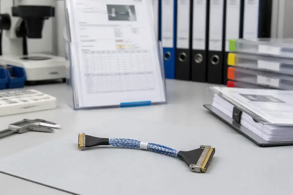
Micro-coaxial assembly document-control scene with records and labels secondary to the harness
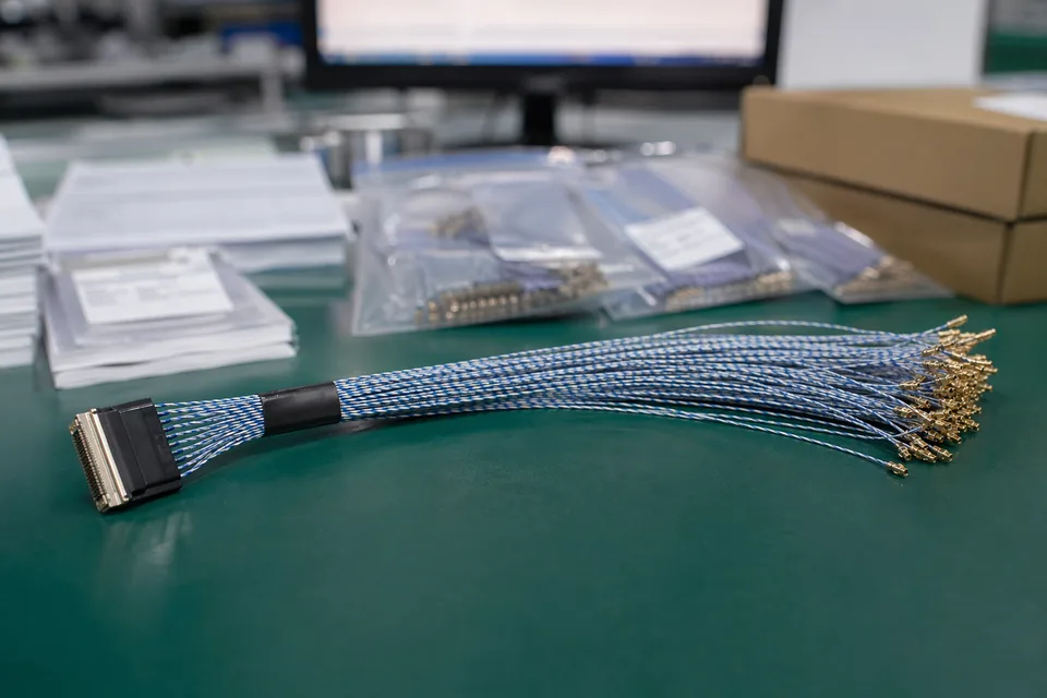
Micro-coaxial controlled record scene with compact harness sample foreground and document support
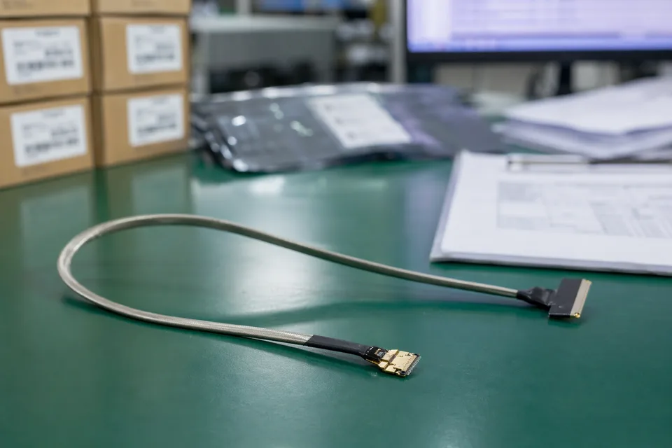
Micro-coaxial batch traceability archive with fine connector lot labels and cable sample visible
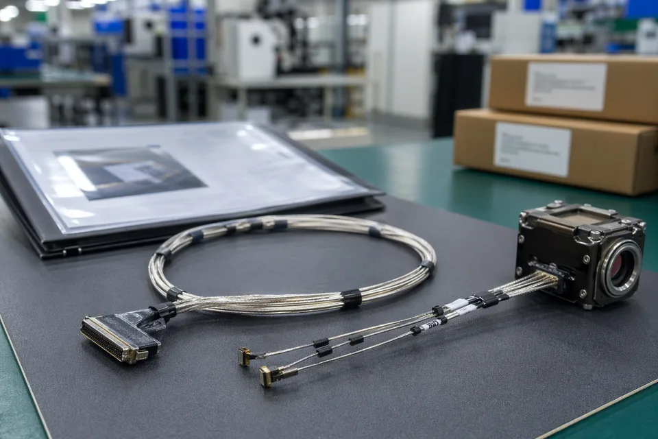
Micro-coaxial released-sample approval folder beside shielded harness and compact module mockup
FAQ
Can you work from an old 0.25mm-pitch sample?
Yes. Old parts help, but pitch, wire-gauge choice, route fit, and the current platform version still need to be checked before the sample can represent the released build.
What is the minimum input for a 0.25mm-pitch quotation?
Send connector references, pitch, wire-gauge context, route notes, project stage, and expected quantity.
Why do 0.25mm-pitch programs need more than a connector reference?
Because wire-gauge choice, local clearance, route geometry, and version scope often decide whether the build can actually be released cleanly.
Can one 0.25mm-pitch assembly cover several versions?
Sometimes, but only if pitch, route geometry, and version scope stay inside the same approved definition.
Can review start before the full drawing package is complete?
Yes. Early review can start from connector references, pitch, route context, and current structure limits, then tighten as the file package becomes clearer.