Specification
Specification Paths and Manufacturing Boundaries
Organize connector, pin-count, pitch, routing-space, and release requirements before narrowing the manufacturing scope.
08 · Featured Specifications
View Specification PageTechnical Reference · MICRO-COAXIAL-CABLE-ASSEMBLIES
Custom Manufacturing
IPC/WHMA-A-620 Workmanship | 100% Tested | Samples in 2 Weeks
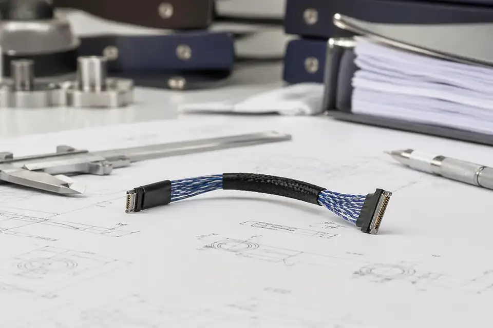
EDPcable specializes in high-precision micro coaxial cable assembly design and manufacturing. We use 100% genuine brand connectors (I-PEX, HRS, KEL, JAE, MOLEX, etc.), covering 32AWG to 48AWG ultra-fine coaxial wire, suitable for laptops, medical devices, industrial cameras, drones, and other demanding applications.
Quick Links
QUICK ACCESSUse the project interface, structure, and application requirements to move into the right content.
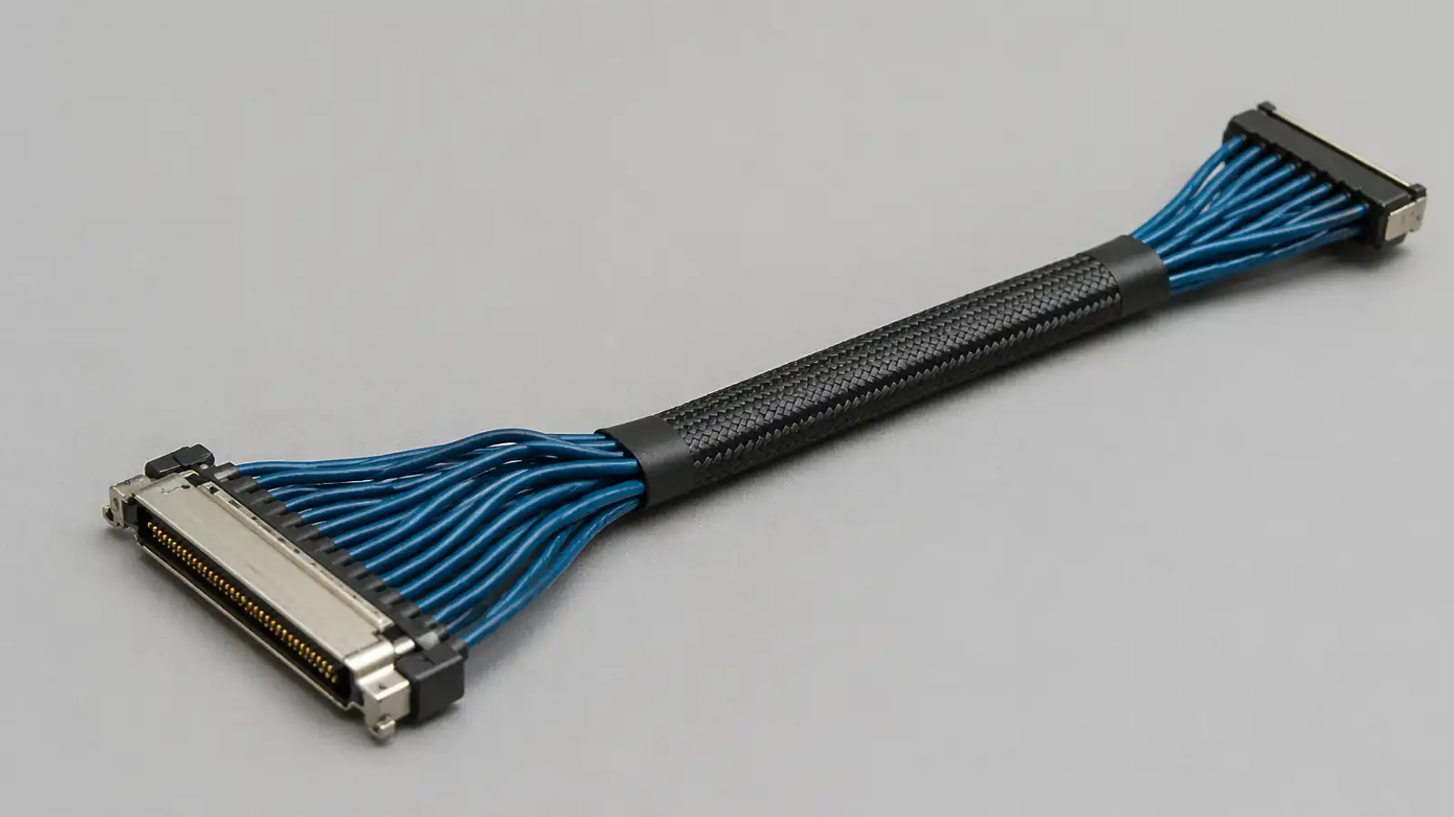
Before detailed specification review begins, most micro-coaxial programs first need to confirm the connector family, pitch, wire gauge, impedance target, shielding structure, and verification scope. This stage is less about rushing into samples and more about defining the technical boundaries correctly.
| 01 | Connector Brands | I-PEX, HRS (Hirose), KEL, JAE, MOLEX, Amphenol, JST, TE |
| 02 | Pitch Range | 0.25mm, 0.3mm, 0.4mm, 0.5mm, 0.8mm, 1.0mm, 1.25mm |
| 03 | Pin Count | 2 - 60 Pin (higher on request) |
| 04 | Wire Gauge (AWG) | 32AWG - 48AWG |
| 05 | Impedance | 50 Ohm standard, custom available |
| 06 | Cable Length | Custom, typically 50mm - 1000mm |
| 07 | Shielding | Single braid, double, foil + braid composite |
| 08 | Temperature | -40C to +85C (extendable) |
| 09 | Pinout | Pin-to-pin (1:1), crossover, custom |
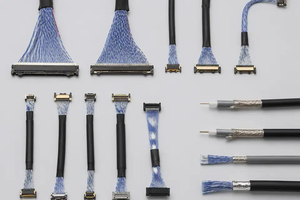
0.4mm pitch solder detail
Multi-cable routing layout
Wire stripping and termination
Organize connector, pin-count, pitch, routing-space, and release requirements before narrowing the manufacturing scope.
Specification
Organize connector, pin-count, pitch, routing-space, and release requirements before narrowing the manufacturing scope.
Use device type, installed position, and validation focus to choose the matching application page.
Application
REF-01For compact medical imaging assemblies and internal signal-routing applications.
Application
REF-02For machine-vision and drone programs that require light, stable coaxial assemblies.
Application
REF-03For HMD, smart-glasses, near-eye display, camera-module, and lightweight wearable routing programs.
Application
REF-04For server, switch, BMC, patch-panel, and hyperscale programs that need dense routing and batch stability.
Micro-coaxial engineering is usually driven less by part count than by whether the connector combination, wire gauge choice, shielding structure, and termination details are already settled. If those points are still in flux, samples, drawings, and process review tend to loop.
Receive connector models, pin definitions, wire specs, length requirements. Confirm wiring method (Pin1-to-Pin1 or custom pinout) and special requirements (impedance, shielding, bend radius).
Match optimal wire and connector combinations. Evaluate production feasibility and identify process risk points (stripping precision for ultra-fine wire, soldering gaps for high-density connectors).
Issue standard engineering drawings with complete pinout definitions, dimensions, BOM, and process requirements — all per IPC/WHMA-A-620 standards.
Production begins only after customer drawing approval. This confirmation step ensures both parties agree on specifications, avoiding rework and waste.
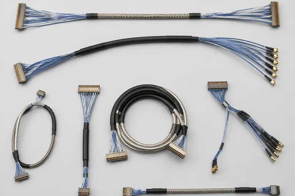
Micro-coaxial engineering drawing set
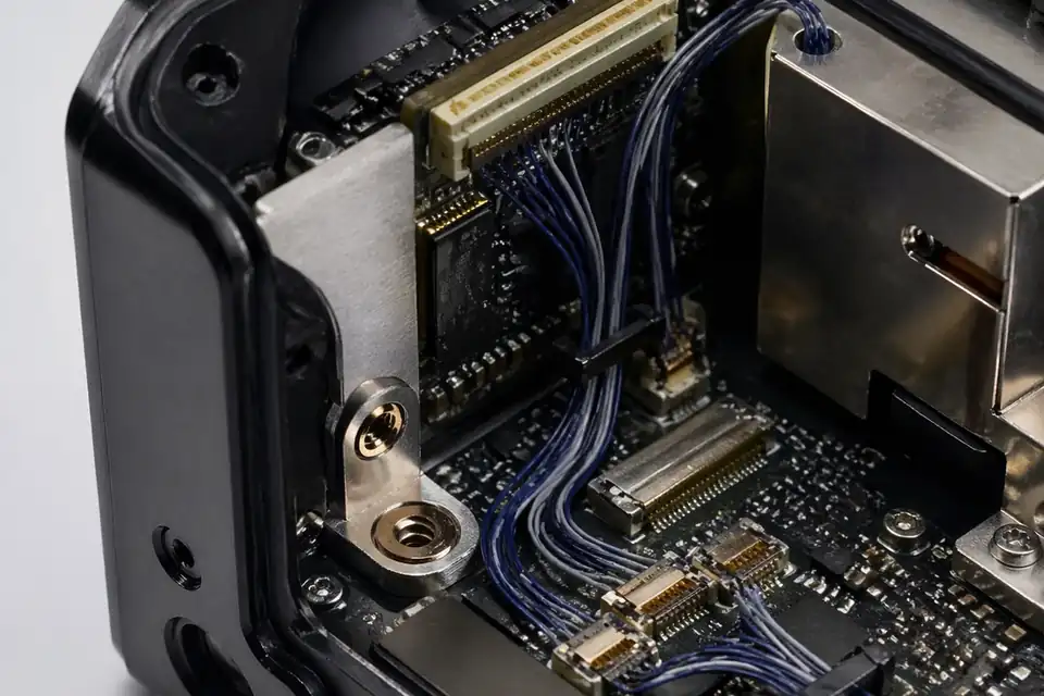
Connector-fit and routing-space review
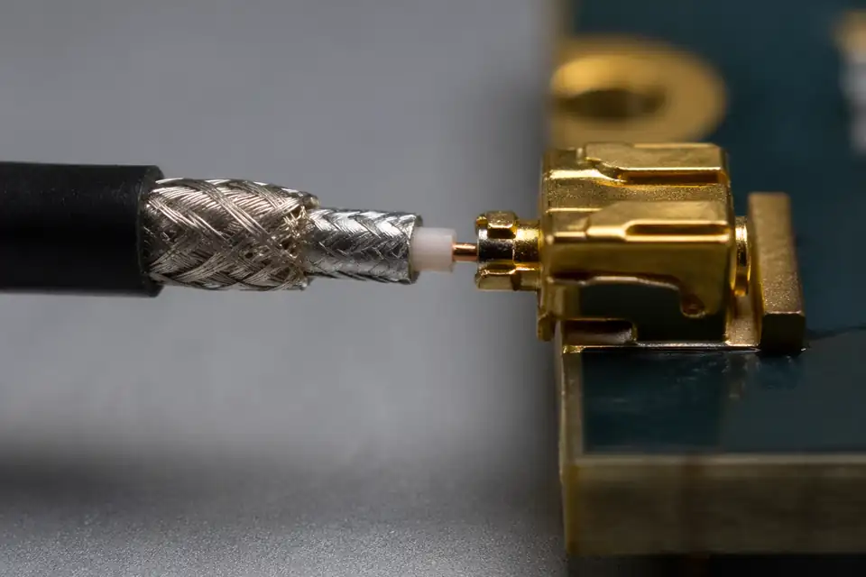
Micro-coaxial programs usually carry tighter requirements around precision termination, impedance consistency, shielding execution, and batch-to-batch variation control. Rather than making broad quality claims, it is more convincing to show the actual risks, verification items, and release criteria. Confidence comes from inspection logic, test results, and version-linked records.
The main micro-coaxial risks usually sit in broken cores, cold solder, impedance drift, weak crimps, and jacket damage. The practical question is not broad quality language, but whether those failure modes are controlled before they turn into batch issues.
Typical verification covers Continuity, Hi-Pot, Insulation Resistance, Pull Force, TDR Impedance, Visual Inspection, together with microscope-based visual inspection, so precision termination, impedance consistency, and assembly condition all stay inside the released limits.
Typical release files include FAIR, OQC Report, IQC Report, Test Report, CoC, with compliance support such as ISO 9001:2015, ISO 13485, and UL when the program requires it.
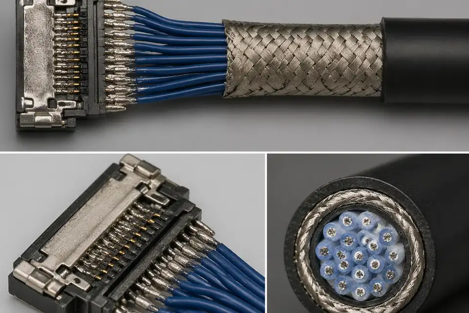
Precision termination and shielding detail
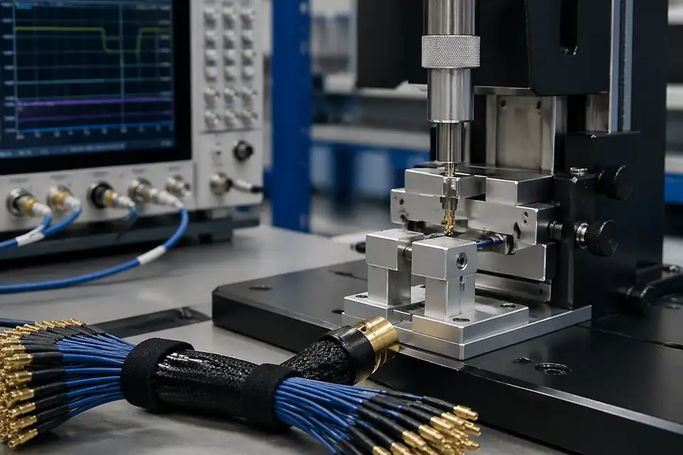
TDR / Hi-Pot / pull-force record
Release file, packaging, and traceability record
Representative programs and real feedback from engineering and sourcing teams
Most micro-coaxial programs move through scope definition, engineering review, sample validation, and controlled production. The clearer that path is, the easier it becomes for sourcing and engineering teams to move the project forward.
Submit your requirements (connector models, wire specs, quantity). We respond with a detailed quote within 1-2 business days.
Our engineering team issues standard drawings with complete pinout, dimensions, and material information.
Production starts only after you approve the drawing — ensuring the final product matches your design intent 100%.
Samples: 2-week standard lead time (3-day rush available). Bulk orders: 4-week standard lead time.
100% inspection completed, packed to your specifications with full quality documentation, then shipped.
Proactive delivery confirmation, installation support, and ongoing technical assistance throughout the product lifecycle.