Technical Reference · HIROSE-DF36
Hirose DF36 Compatible Interface
Custom Micro-Coax Cable Assemblies Compatible with Hirose DF36 Connectors
For fine-wire micro-coax programs where the BOM, drawing, or sample already locks the Hirose DF36 connector system
EDPcable provides custom micro-coaxial cable assemblies that mate with Hirose DF36 connector systems — for projects where the connector series is already identified in the BOM, drawing, legacy part, or sample, and what still needs review is the variant version, mating relationship, wire gauge, shield grounding, and route space. DF36 usually appears in gimbals, camera modules, and small hinge structures, where space and bending conditions are often more demanding than the connector itself; confirming them before quotation lets the sample match the installed environment in one pass.
Quick Links
QUICK ACCESSStart with the sections closest to the project structure, interface requirements, and validation scope.
Hirose DF36 Compatible Project Overview
Once a fine-pitch vertical-mating interface like DF36 is locked, review centers on how variant version, pin count, wire gauge, and route space combine — not on whether a micro-coax assembly can be built at all.
| NO | Review Item | Typical Range or Meaning |
|---|---|---|
| 01 | Page Type | Connector / brand-compatible manufacturing entry |
| 02 | Typical Interface | Hirose DF36 series (including variants such as DF36A) or the DF-family fine-pitch interface specified in the customer BOM |
| 03 | Series Reference Parameters | 0.4mm pitch, vertical mating, low profile; commonly paired with fine-gauge micro-coax; final values follow the original-maker catalog and the customer drawing |
| 04 | Typical Programs | UAV gimbals, surveillance and action-camera modules, small hinge devices, compact high-speed signal paths |
| 05 | Key Inputs | Full part number and variant, mating side, pin count, wire gauge, shield grounding, bend radius and route space |
| 06 | Boundary Risk | DF36 and variants such as DF36A are not interchangeable by default; vertical mating constrains assembly direction and loading |
| 07 | Release Basis | Customer-confirmed drawing, BOM, sample, mating reference, and version boundary |
Compatibility Review Inputs
Use these items as first-round review inputs so the discussion does not rely on the page label alone.
Provide the full connector series, variant suffix, BOM, or legacy-part photos.
Provide the mating side, pin count, wire gauge, and shield-grounding requirements.
Describe the bend radius, motion pattern, retention points, and local space.
State the project stage, sample quantity, pilot quantity, and target lead time.
For legacy replacement or multi-model platforms, state the applicable version boundary.
Connector Compatibility Boundary
The easiest traps in DF36 projects are variant boundaries and assembly direction: the series name matches, but DF36 and variants such as DF36A differ in structural details, and the vertical-mating structure has its own demands on assembly loading and removal space. The conditions below should be walked through one by one before quotation and sampling.
| NO | Review Item | Why It Matters | Suggested Input |
|---|---|---|---|
| 01 | Full part number and variant | Variants such as DF36 / DF36A differ in structural details and cannot be assumed interchangeable by series name | BOM, drawing, purchasing part number, or clear photos |
| 02 | Mating-side interface | Wire end and board end must be reviewed against the actual mating relationship, and the vertical-mating alignment needs confirmation | Mating connector model, board-side position, or a sample |
| 03 | Pin count and wire gauge | The pin-count and wire-gauge combination drives bundle diameter, flexibility, and the termination process path | Pin count, AWG, signal requirements |
| 04 | Shielding and grounding | Shield handling and grounding on fine-gauge micro-coax directly affect EMI behaviour | Shield structure, grounding-point definition, system-level EMC conditions |
| 05 | Bending and route space | Repeated bending and twisting in gimbal and hinge scenes decide cable structure and life expectations | Bend radius, motion pattern, route sketch or 3D space |
| 06 | Version boundary | When several models share one series, define which versions the sample represents | Platform versions, replacement scope, legacy-part differences |
Compatibility Review Inputs
Before the RFQ stage, try to send the materials below in one pass. The more complete they are, the easier it is to judge whether the project belongs on this connector-review page or on the 0.25mm-pitch or high-shielding pages.
Customer Pain Points
Connector-led micro-coax projects tend to run into the same pain points. The early confirmations below keep them from surfacing after sampling.
| NO | Customer Pain Point | Risk from the Connector-Model View | Confirm Early |
|---|---|---|---|
| 01 | Product design issues | The series name is locked but the variant or mating does not match, so the sample cannot fit the hinge space | Full part number, mating side, route space |
| 02 | Product quality issues | Termination and shield handling drift in bending scenes and intermittent signal faults appear in volume | Wire gauge, shield-grounding plan, first-article confirmation |
| 03 | Lead-time issues | Only the series name "DF36" is given, engineering keeps chasing variant and mating details, and the sample schedule slips | BOM, drawings, legacy-part samples |
| 04 | After-sales issues | Several models share one series with different variants, and field replacements do not match | Platform versions, batch labels, release records |
| 05 | Complaint-handling issues | A replacement looks similar but its variant boundary differs, making tracing difficult | Legacy-part photos, active version, replacement scope |
| 06 | Pricing issues | Quoting by brand series alone misses wire gauge, flex life, and assembly complexity | Structure, motion conditions, quantities, validation requirements |
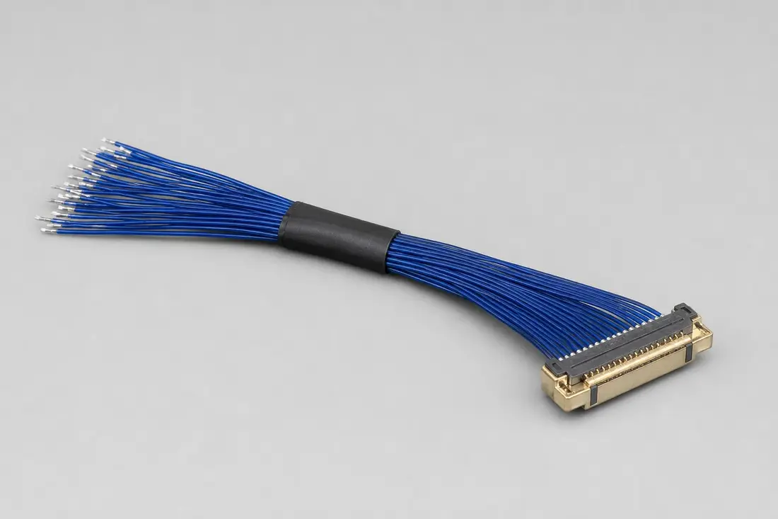
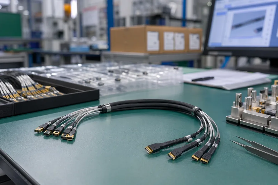
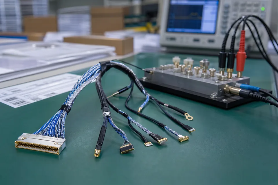
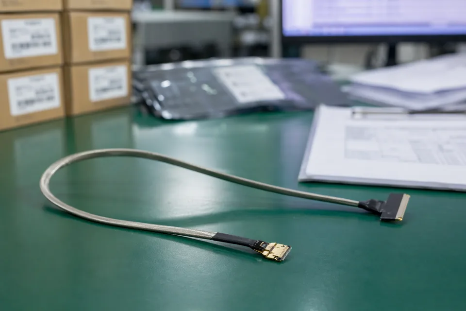
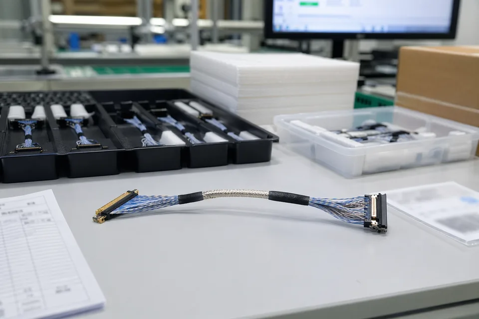
Connector-Compatibility Visuals
IMAGES · 01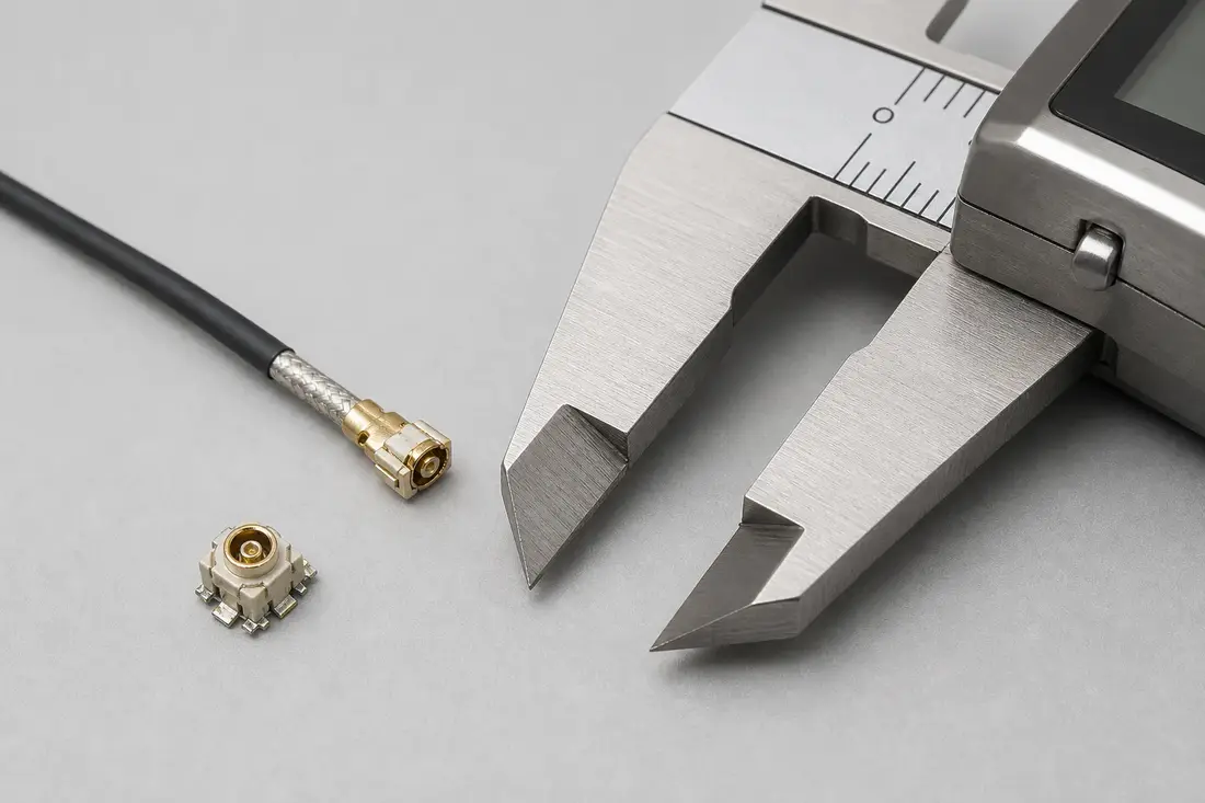
Connector-compatibility review photo for a DF36-compatible micro-coax harness: low-profile board connector, fine coaxial cable end, a separate mating-reference connector, and a digital caliper
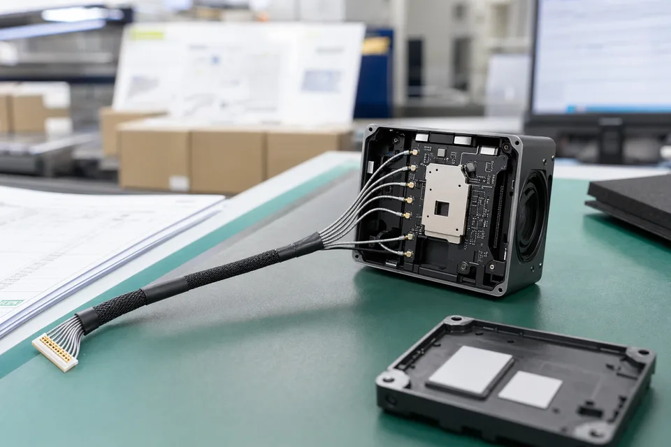
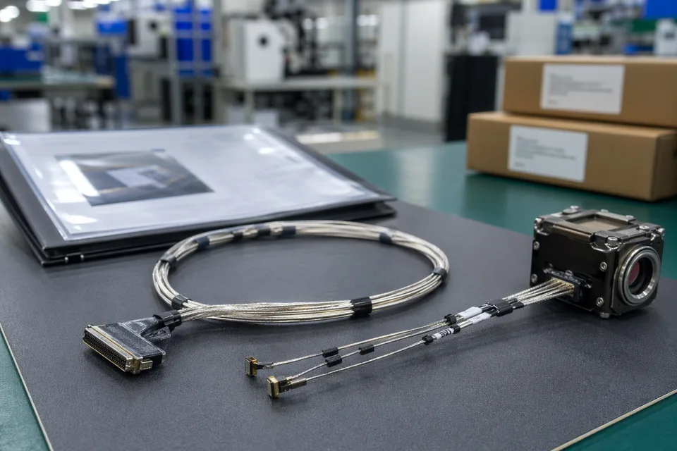
Typical Applications
DF36-type projects mostly land in the combination of small space, moving structures, and high-speed signals. Below are the common scenes and their review focus; fuller device context lives on the corresponding application pages.
Application Scene
IMAGES · 01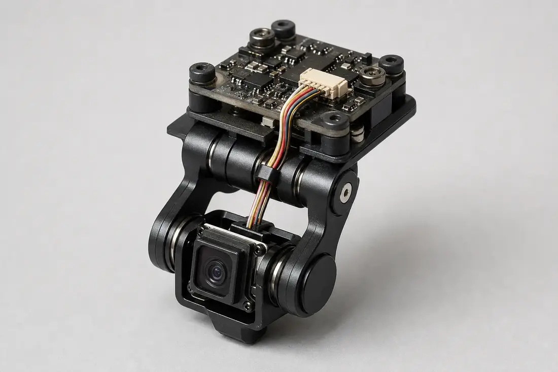
Drone camera gimbal module with a fine micro-coax cable routed through the hinge to the camera board
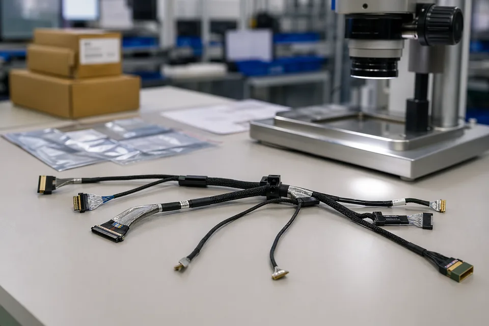
Factory Strength and Project Support
DF36-class projects usually need fine-gauge work, motion-scenario experience, sample speed, and version records to come together at once. The points below are the main factory-side references for early RFQ discussion.
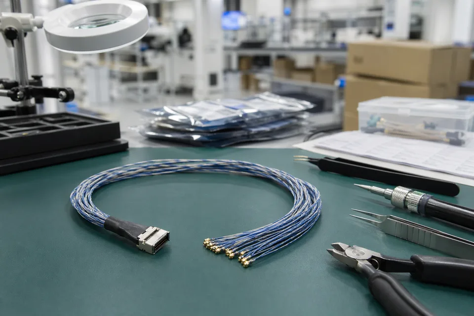
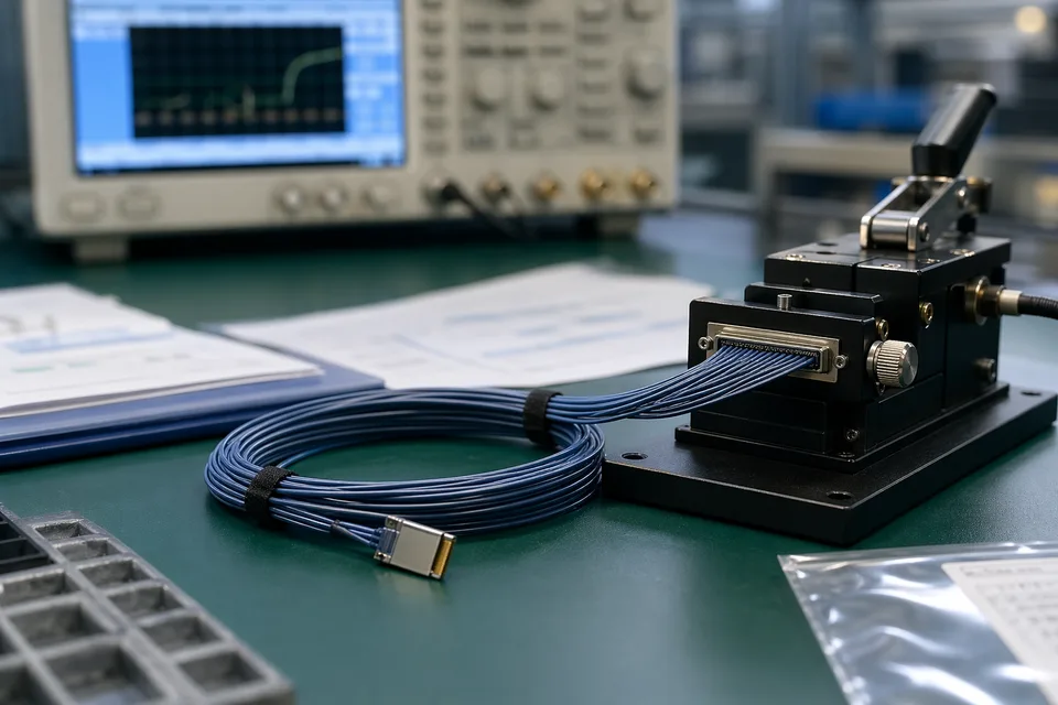
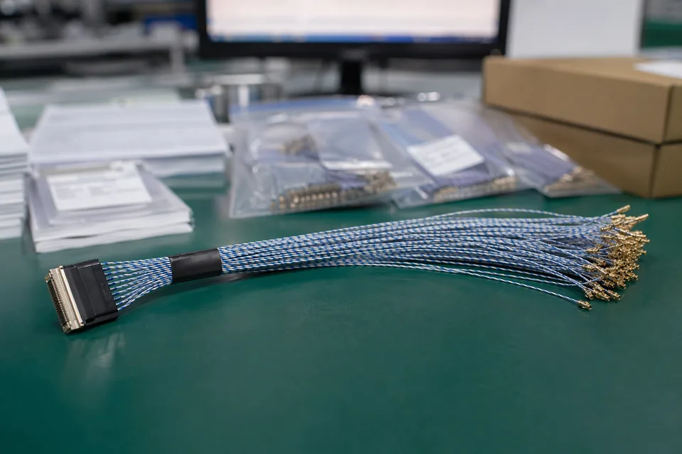
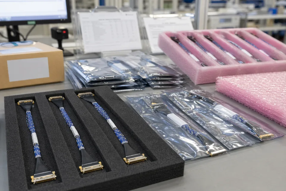
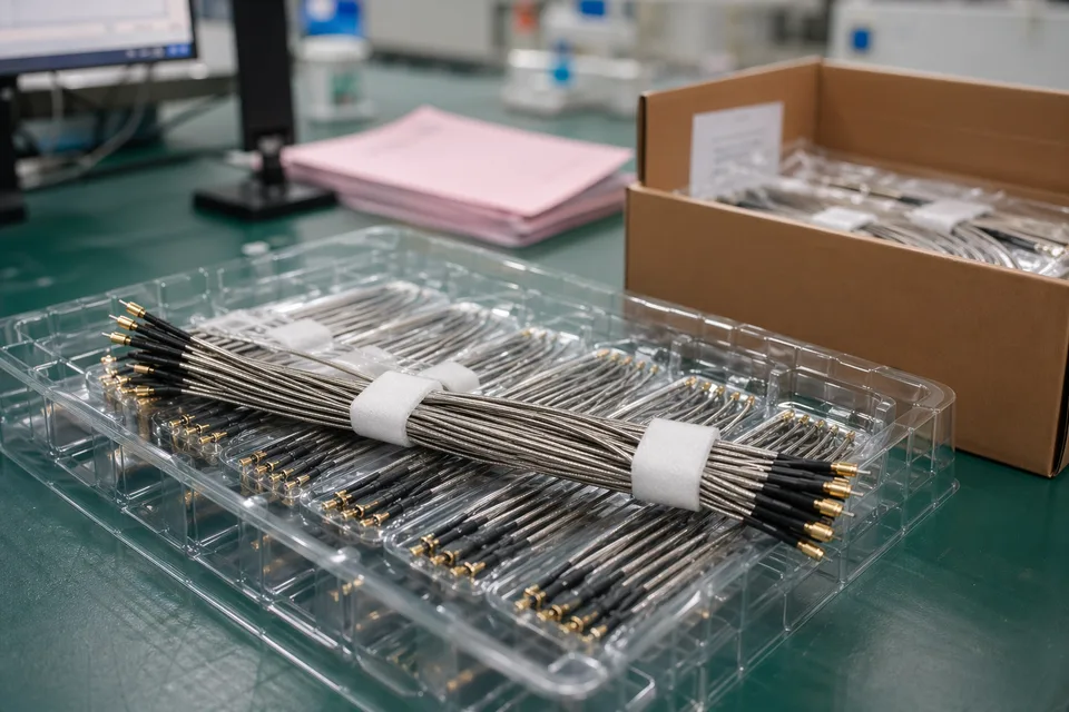
Factory / Production Visuals
IMAGES · 04
Micro-coaxial samples, fixtures, and a fine-assembly workstation
Sample harnesses, fixtures, and a packaging-preparation bench
Termination fixture and harness-consistency check
Finished assembly organization, protective packaging, and shipment preparation
Fine-gauge micro-coax manufacturing cooperation
We can run compatible cable-assembly manufacturing reviews around the customer-specified interface system, wire gauge, shielding, and motion-path conditions.
Sample and low-MOQ support
Lower MOQ and sample-first starts can be supported, so a program can complete mating, installation, and motion validation before committing to larger batches.
Structure and version records
Cable structure, connector references, and shipping labels are kept tied to the same version definition to reduce replacement risk.
Project response
Technical and after-sales inquiries usually receive a first response within one business day.
Engineering Capability
Engineering value on a DF36-compatible page comes from settling variant, mating, and route questions before release rather than on the production line.
Engineering Capability
Confirm the variant before the price: the DF36 series name is only a starting point — variant version, mating side, and assembly direction decide the manufacturable path.
Treat route conditions as the first input: in gimbal and hinge scenes, bend radius and motion pattern often decide the cable structure earlier than the connector does, so review them together at the drawing stage.
Set the version boundary before sampling: legacy replacements and multi-model platforms must state up front which versions can share a build and which need separate samples.
Quality and Verification Highlights
Termination and shielding consistency carry motion scenes: batch stability of fine-gauge micro-coax under repeated motion depends on consistent termination workmanship and shield handling.
Inspection output corresponds to the connector reference: first-article confirmation, OQC, and shipment labels should trace back to the same drawing version and part reference.
A brand name does not replace engineering confirmation: a brand series is not confirmed compatibility — the customer drawing and sample remain the basis.
Evidence Chain
Variant and mating confirmation records
Fix the full connector reference, mating side, and current version boundary as the sample-review basis.
Route and structure review records
Record wire gauge, shielding, bend zones, and motion conditions so samples stay aligned with the installed environment.
Sample and batch tracing
Keep sample confirmation, shipment labels, and batch files pointed at the same released version.
Engineering, Quality, and Record Visuals
IMAGES · 04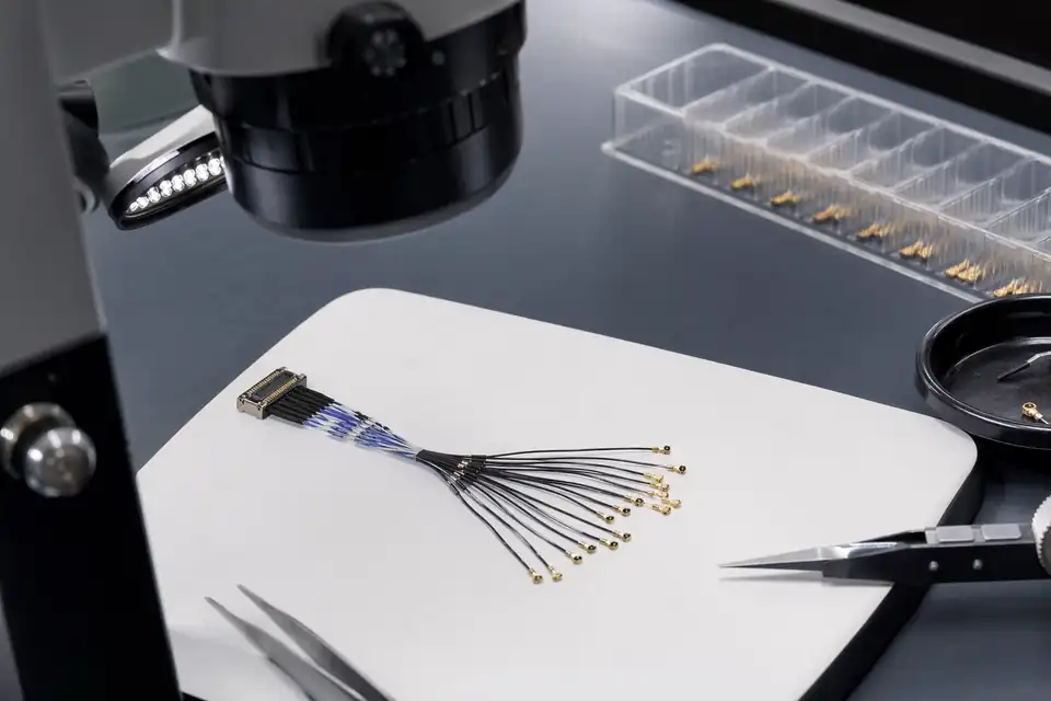
Micro-coax connector end-section inspection with unreadable drawing reference
Bend-zone and route-fit verification for a DF36-compatible micro-coax build
Sample confirmation record scene with documents kept unreadable
Batch label and version-tag detail with micro-coax sample context
DF36-Compatible Micro-Coax Project Flow
These projects run best when interface, variant, and route conditions are confirmed first, then quotation, drawing, sample, and batch follow.
Send connector and project inputs
Provide the full part number, mating side, legacy-part photos, drawings, wire gauge, length, motion conditions, and quantity rhythm.
Interface and manufacturability review
Variant mating, wire gauge, bend path, termination boundary, and version risk are assessed together.
Quotation and sample-scope confirmation
Connectors, cable, process, inspection, and delivery files are all placed inside the quotation boundary.
Drawing and sample-basis confirmation
The connector reference, route, dimensions, and assembly requirements of the current version are fixed.
Sample production
Samples are built against the confirmed basis, validating mating, route, and installation fit first.
Sample testing and feedback
The customer completes installation, signal, or motion validation, then feeds back the change boundary.
Small-batch or volume confirmation
Production starts under control once version, sample, and lead time are all confirmed.
Files, Records, and Brand Boundary
Credibility in a DF36-compatible project comes from traceable drawings, samples, and version records — not from unverified brand-authorization wording.
Connector reference records
The customer-specified series, variant, and mating relationship are recorded for later repeat orders.
Sample confirmation and inspection records
Sample confirmation plus appearance, continuity, and key-dimension checks correspond to the current version.
Batch labels and shipment files
Batch labels, carton marks, packing details, and agreed accompanying documents are supported.
Brand boundary note
Third-party brand names identify the compatible interface direction only and do not imply agency, authorization, or official cooperation.
Certifications / Records Visuals
IMAGES · 04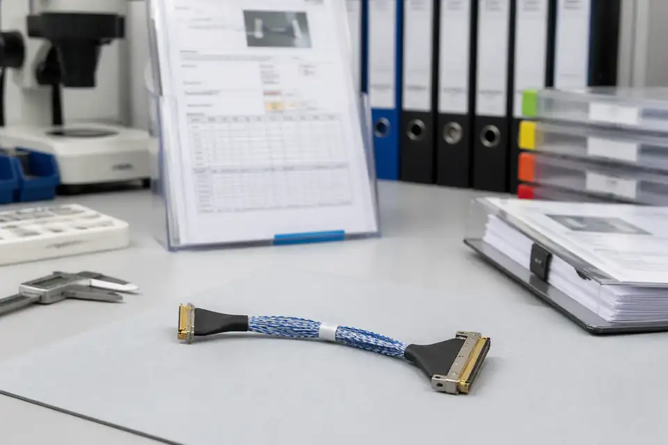
Unreadable inspection record and batch label detail with micro-coax sample tray
Controlled-document folder kept closed beside a packaged DF36-compatible harness
Batch traceability cards and carton-mark context with protected samples
Released-version file sleeve with micro-coax packaging preparation
Shipping
Fine-pitch connectors and micro-coax harnesses need focused protection for connector ends, bend zones, and label information.
Connector-end protection
Anti-static bags, foam, trays, or separated packaging reduce crush load on connector ends.
Batch and version identification
Batch labels, carton marks, and version information can follow project requirements.
International shipping coordination
Customer courier accounts and supplier-arranged shipping are both supported, with logistics information shared.
Packaging and Shipping Visuals
IMAGES · 04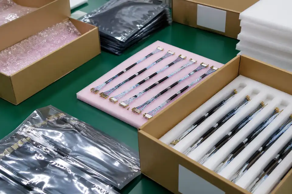
Micro-coax samples in anti-static bags with foam padding
Batch labels and carton marks on protective packaging
Foam-lined tray with protected fine-pitch connector ends
Carton staging for international courier handoff
FAQ
Trademark and Brand Notice
Hirose is a trademark of Hirose Electric Co., Ltd., and DF36 is a product-series designation of its connectors. These names are used only to identify the interface-mating direction of the current project. The products on this page are compatible cable assemblies independently designed and manufactured by EDPcable, with no agency, authorization, distribution, or cooperation relationship with Hirose Electric Co., Ltd. When a customer drawing or BOM has locked the Hirose DF36 connector system, we provide custom harness manufacturing that mates with that interface; final delivery follows the mutually confirmed drawings, samples, and engineering definitions.