Specification
REF-01Board-to-Panel LVDS
For LVDS links between control boards and display panels in internal display systems.
LVDSDisplayBoard to Panel
View Specification PageTechnical Reference · LVDS-CABLE-ASSEMBLIES
Differential Display Interconnects
LVDS Cable Solutions for Medical, Industrial, and Embedded Display Programs
EDPcable manufactures custom LVDS cable assemblies for medical monitors, industrial display equipment, digital signage, and embedded display systems. In projects like these, the first question is rarely one isolated parameter. What matters first is whether the interface definition is clear, whether the differential routing is correct, whether the shielding structure fits the installation environment, and whether samples, drawings, and production can stay aligned under one controlled definition. For OEM programs that still rely on LVDS architecture, signal stability, controlled structure execution, and clear engineering release remain critical.
Quick Links
QUICK ACCESSUse the project interface, structure, and application requirements to move into the right content.
Before moving into detailed specification review, most teams need to confirm the pin range, signal structure, connector system, routing space, shielding requirements, and verification scope. The clearer that definition is, the smoother the review and sample process becomes.
| 01 | Typical Pin Range | 20 Pin - 50 Pin |
| 02 | Typical Applications | Medical monitors, industrial displays, digital signage, embedded display systems |
| 03 | Signal Structure | LVDS differential signaling with paired routing and project-specific shielding |
| 04 | Connector Systems | Project-based LVDS display connectors from mainstream OEM ecosystems |
| 05 | Cable Styles | Standard LVDS harnesses, shielded assemblies, braided variants, and custom routed structures |
| 06 | Key Focus | Differential consistency, signal stability, shielding execution, and installation fit |
| 07 | Length Range | Custom by device layout and installation space |
| 08 | Verification | Continuity, insulation, visual inspection, and project-specific electrical checks |
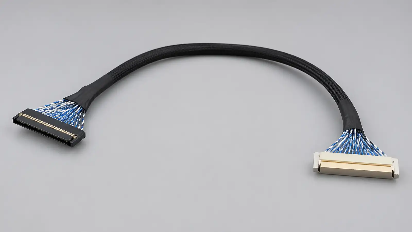
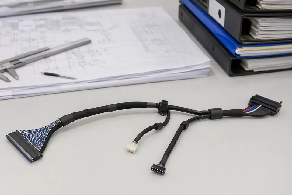
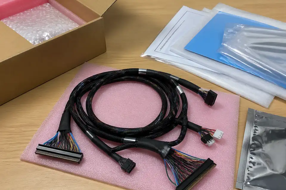
LVDS routing layout reference
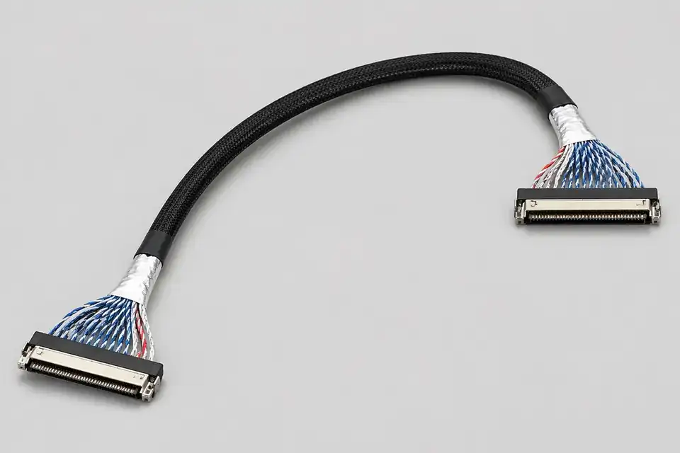
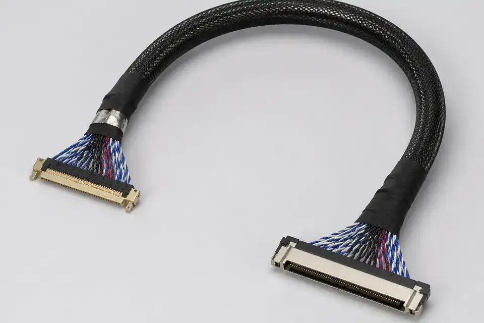
Shielded harness detail
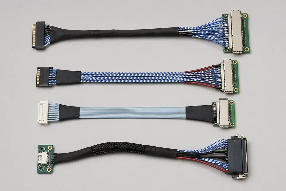
Display-side connector detail
Organize connector, pin-count, pitch, routing-space, and release requirements before narrowing the manufacturing scope.
Specification
REF-01For LVDS links between control boards and display panels in internal display systems.
Specification
REF-02For LVDS harnesses that need stronger shielding execution and stable long-term installation fit.
Specification
REF-03For LVDS projects where pin count, connector family, pin mapping, shielding, and route release need review together.
Specification
REF-04For LVDS display projects where the JAE FI-X connector system is already fixed and cable-side / panel-side mating, lock type, and pin count need a compatibility review.
Use device type, installed position, and validation focus to choose the matching application page.
Application
REF-01For industrial display and monitor programs that still rely on LVDS interconnect architecture.
Application
REF-02For embedded systems that continue to use LVDS display interfaces in controlled internal layouts.
Application
REF-03For diagnostic displays, bedside screens, and medical workstations that still rely on LVDS display harnesses.
LVDS projects usually carry more engineering sensitivity than ordinary cable builds. Interface definition, differential routing, shielding structure, length control, and installation space all influence whether samples assemble cleanly, drawings can be released under control, and production stays repeatable.
Confirm pin count, connector system, signal-path expectations, and display-side interface details before sample release.
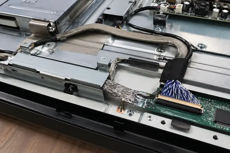
Review twisted-pair structure, shielding level, route length, bend space, and fixing conditions to ensure the design fits the installation environment and remains repeatable in production.
Freeze dimensions, pin mapping, connector references, and key process notes in a controlled drawing so samples and production stay aligned to one definition.
Move into sample or production only after interface logic, drawing definition, and release requirements are all confirmed.
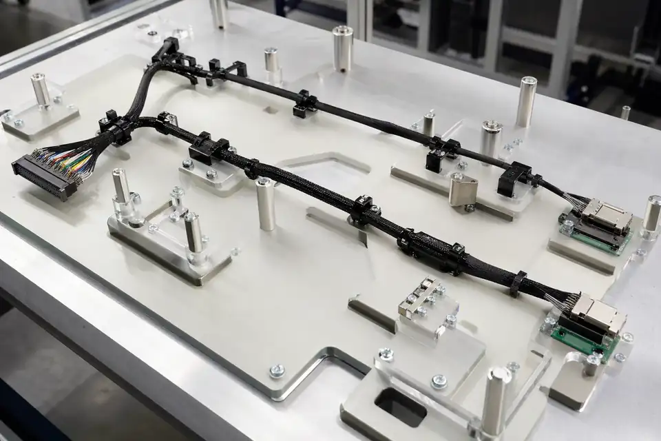
LVDS engineering drawing set
Shielding and routing review
LVDS programs usually carry tighter requirements around differential consistency, shielding execution, and repeatable assembly quality. Broad quality claims are less persuasive than stable structure execution, repeatable assembly control, and production builds that stay aligned with the approved sample and drawing. Clear verification logic and shipment-side records are what make that confidence visible.
Common issues in LVDS work include unstable differential structure, inconsistent shielding execution, pin-mapping errors, and weak assembly repeatability across batches.
Continuity and insulation are only the starting point. Differential consistency, structural fit, workmanship, and project-specific electrical checks also need to be verified clearly.
FAIR, OQC reports, inspection records, and conformance files matter because they tie each shipment back to the approved drawing, sample definition, and production requirements.
Assembly risk-control reference
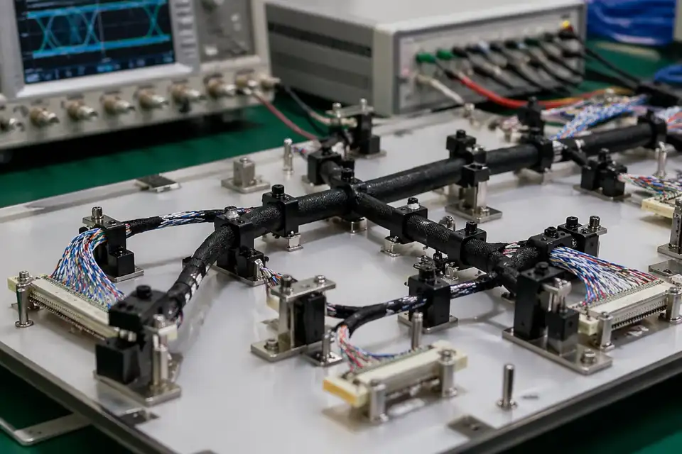
Electrical verification and inspection record
Shipment-side support document set
Medical monitor programs, industrial display integration, and digital signage platforms are three of the most common LVDS project types. Each one places a different emphasis on engineering, quality, and delivery.
Most LVDS programs move through scope definition, engineering review, sample validation, and controlled production. The clearer that path is, the easier it becomes for sourcing and engineering teams to move the project forward.
Start from interface definition, application context, target length, and expected quantity so technical review begins from a clear scope.
Review pin mapping, shielding structure, routing conditions, and manufacturability before the project moves into sample build or production.
Use drawing confirmation, sample build, and project-side validation to confirm that the structure is suitable for formal release.
Move into controlled production, final inspection, and shipment support under the approved definition, with the relevant records tied back to the released build.