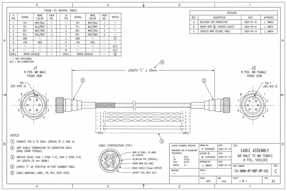
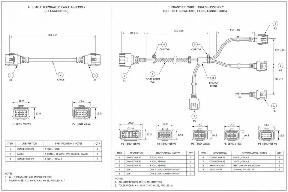
Read a cable assembly drawing by checking the released document set, connector views, pin-to-pin map, finished dimensions, material callouts and acceptance notes together. This guide shows how a connector face can reverse your interpretation, why a cut-wire length is different from a finished length
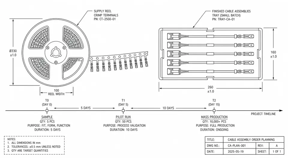
Cable assembly MOQ and lead time must be confirmed for the exact drawing revision and purchase scope. A connector reel quantity is not automatically the minimum number of finished assemblies: stock, distributor packaging, setup charges and ownership of unused material can change
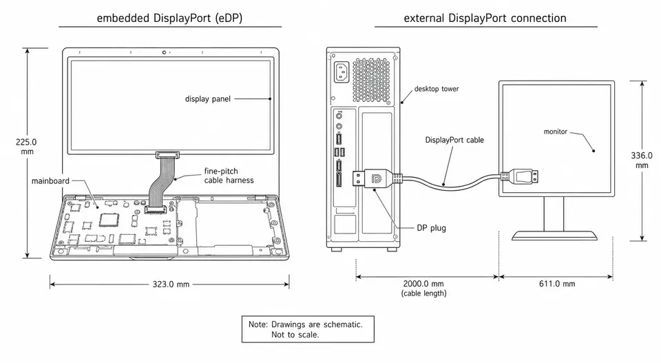
eDP normally connects a graphics source to an internal panel; external DisplayPort connects a source to a monitor through a defined external interface. Their shared signaling heritage does not make their cables interchangeable, but it also does not mean every connection requires protocol conversion.
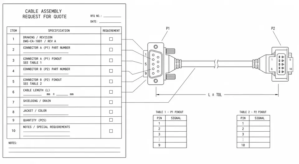
When a cable assembly quote drags through round after round, the supplier usually isn't slow — the RFQ is just missing the few details that let anyone scope the build. An RFQ that can be quoted accurately on the first pass needs to spell out a handful of dimensions: a drawing or an old sample, full
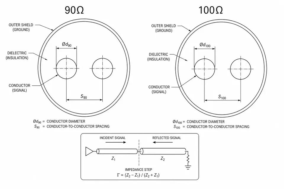
A 90-ohm cable is not automatically interchangeable with a 100-ohm cable, and neither nominal value identifies every high-speed interface. Start with the exact protocol revision, endpoint requirements and channel definition. This guide separates differential characteristic impeda
I-PEX, Hirose and JAE series names are discovery clues, not a cross-reference. A valid replacement or mating decision requires exact plug and receptacle part numbers, manufacturer-defined mating information, dimensions, cable compatibility, electrical ratings and application constraints. This articl
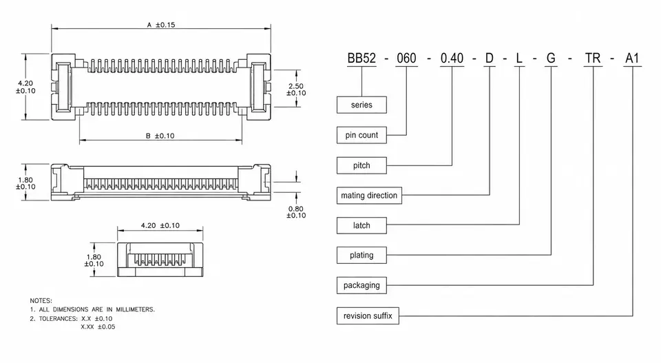
Read a connector part number with the ordering guide for its exact manufacturer and series. Start with the complete string, then distinguish the physical product identifier, the packaging order code and the drawing revision. They answer different questions. This guide uses IRISO'
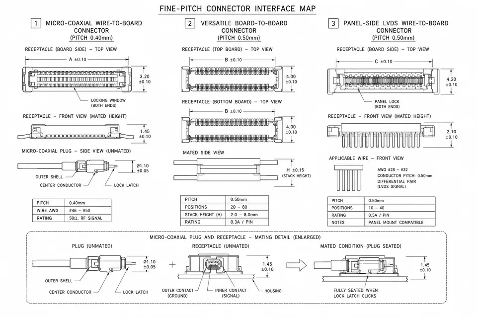
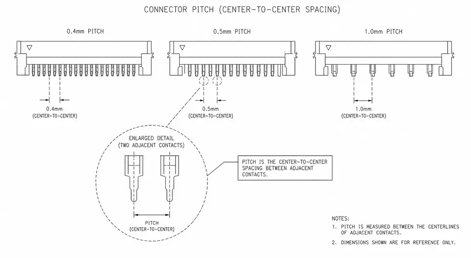
Connector pitch is a spacing dimension, not a complete connector specification. Start with the manufacturer's drawing, identify the contact pattern and measurement direction, and separate contact pitch from row spacing, PCB tail spacing and cable conductor pitch. This guide works
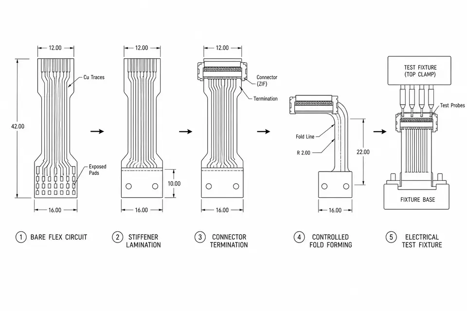
FPC assembly turns a fabricated flexible circuit into a defined interconnect or populated assembly. The route depends on the actual drawing: a bare connector tail, soldered component and flex-to-wire joint need different controls. This guid
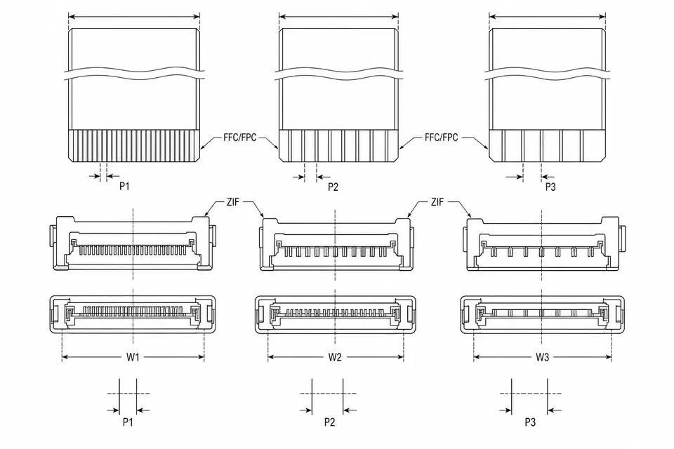
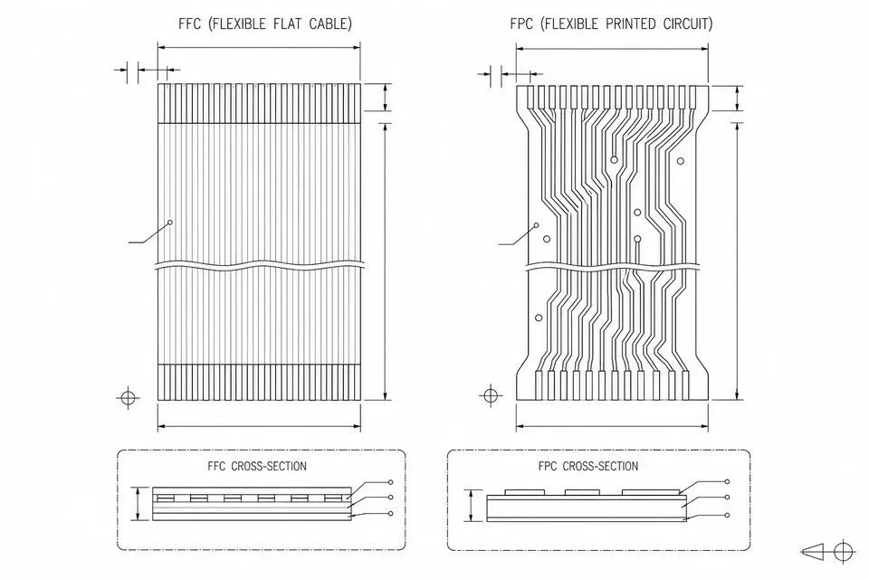
Choose FFC pitch from the exact connectors at both ends, then verify cable-end geometry, current conditions and installed space. This guide shows how to estimate pitch from conductor-center span, why finished cable width is a separate drawing dimension, and what a same-pitch repl
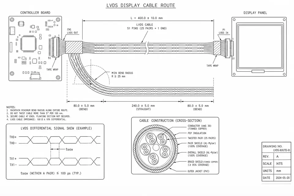
LVDS cable reach must be validated for the exact transmitter, receiver and installed channel; neither 2 m nor 5 m is automatically qualified. This guide turns pixel clock into lane rate for a specific 7:1 display mapping, separates data-to-clock skew from differential-pair imbalance, and explains wh
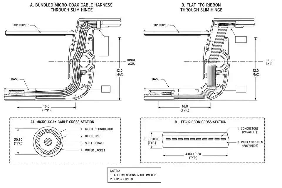
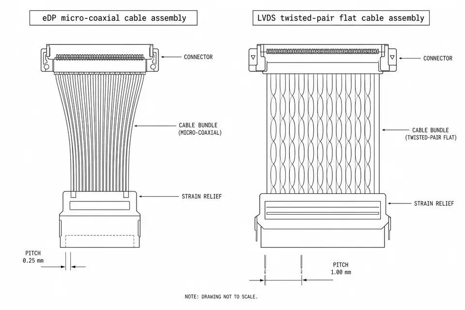
Compare micro-coax and FFC by the complete cable and connector system, not a universal speed or hinge-life claim. This guide separates construction from qualification, explains why shielded and high-speed FFC options remain candidates, and maps the shielding transition into the c
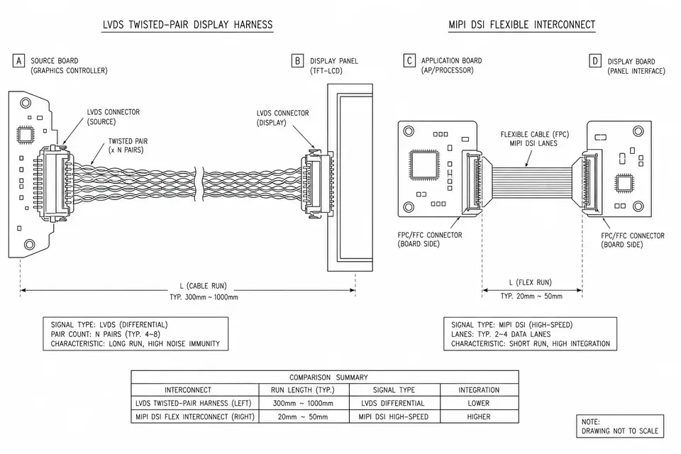
Choose LVDS or MIPI DSI from the exact processor, panel and interconnect, rather than a universal cable-length rule. LVDS describes electrical signaling; DSI describes a display protocol with a specified physical layer. This guide separates those boundaries, compares the information needed at each e
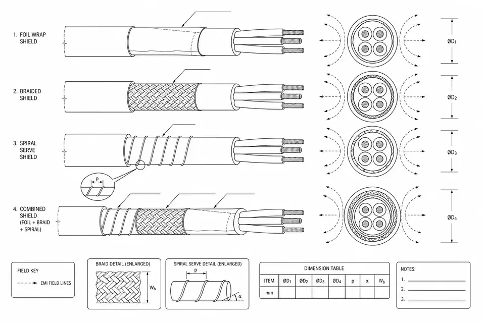
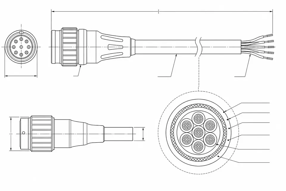
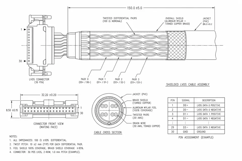
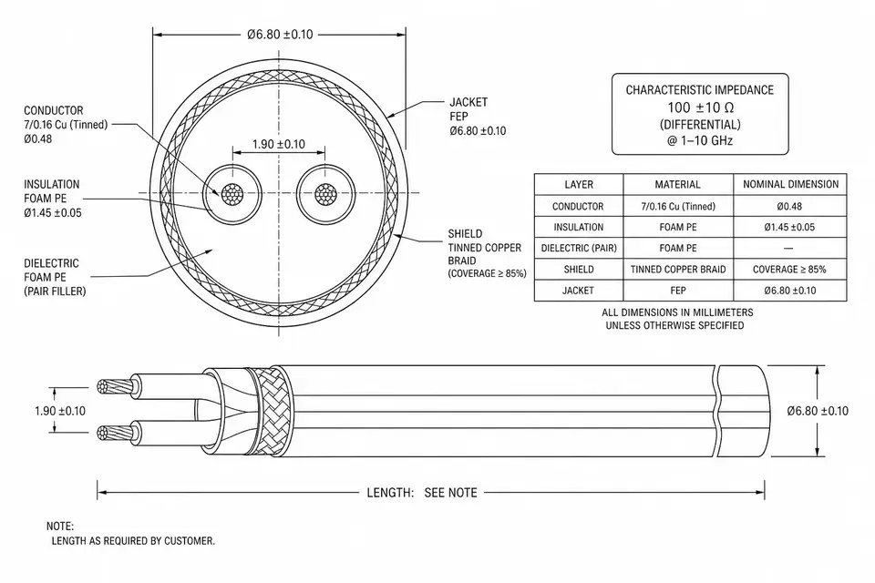
Cable shielding reduces unwanted coupling through a conductive structure around the signal conductors, but the installed result depends on the complete current path. Foil, braid, spiral and combined shields describe construction rather than a guaranteed frequency range or flex life. This g
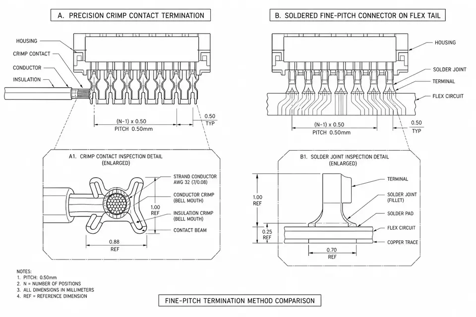
Crimping and soldering are not interchangeable defaults. The exact terminal application specification, approved wire or cable construction, tooling/process inputs, environment and validation plan determine the termination. Fine pitch or wire size alone does not create a universal cutoff or reliabili
A cable assembly typically centers on a terminated cable, while a wire harness centers on a routing network of wires and branches. Real products can combine both, and industry terminology overlaps. This guide compares construction, drawing inputs, routing, tooling, maintenance an
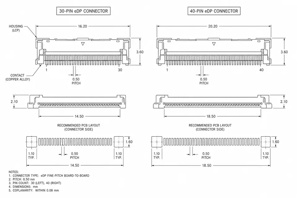
A 30-pin or 40-pin eDP connector identifies a contact count, not a complete display specification. Neither count proves resolution, refresh rate, touch support or interchangeability. This guide explains how to identify a replacement cable from the original panel label, motherboar
ISO 13485 is the quality management system standard for medical devices. For someone sourcing medical cable harnesses, it isn't a certificate on a wall — it's about how traceability, lot records, change control, and process validation land on every cable. This primer clarifies a few things: how ISO
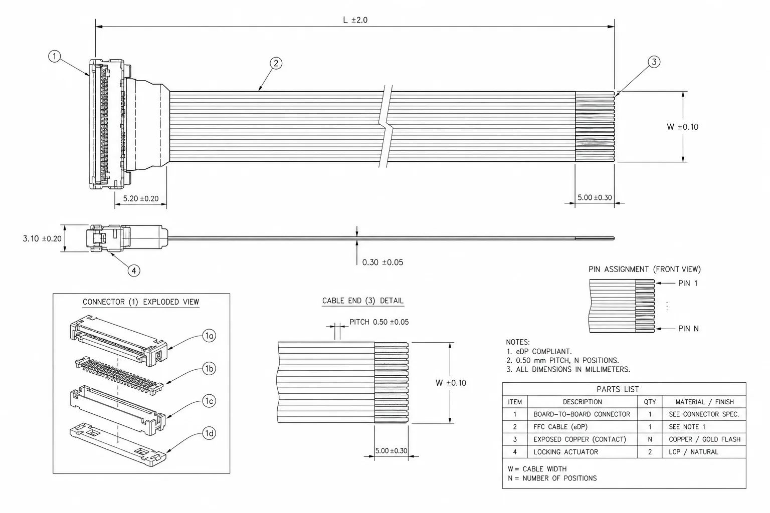
eDP (Embedded DisplayPort) is an internal display interface defined by VESA. It carries display data between the mainboard and panel in laptops, tablets, and industrial or medical displays. An "eDP cable" is the finished harness that implements the Main Link, AUX, and HPD connections for one panel i
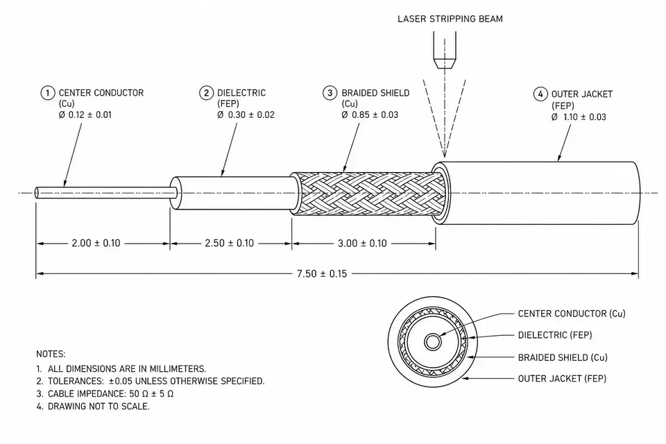
Laser stripping prepares micro-coax terminations by removing selected jacket, shield or dielectric material. It can reduce the mechanical force applied by a cutting blade, but a non-contact process still needs qualification for the actual material stack. This guide explains why j
LVDS (Low-Voltage Differential Signaling) is a way of moving data across a pair of wires using a small voltage difference between them — robust against noise, low-power, and low-EMI. In displays it usually appears as FPD-Link, packing the data pairs and clock a panel needs into one harness, and it i
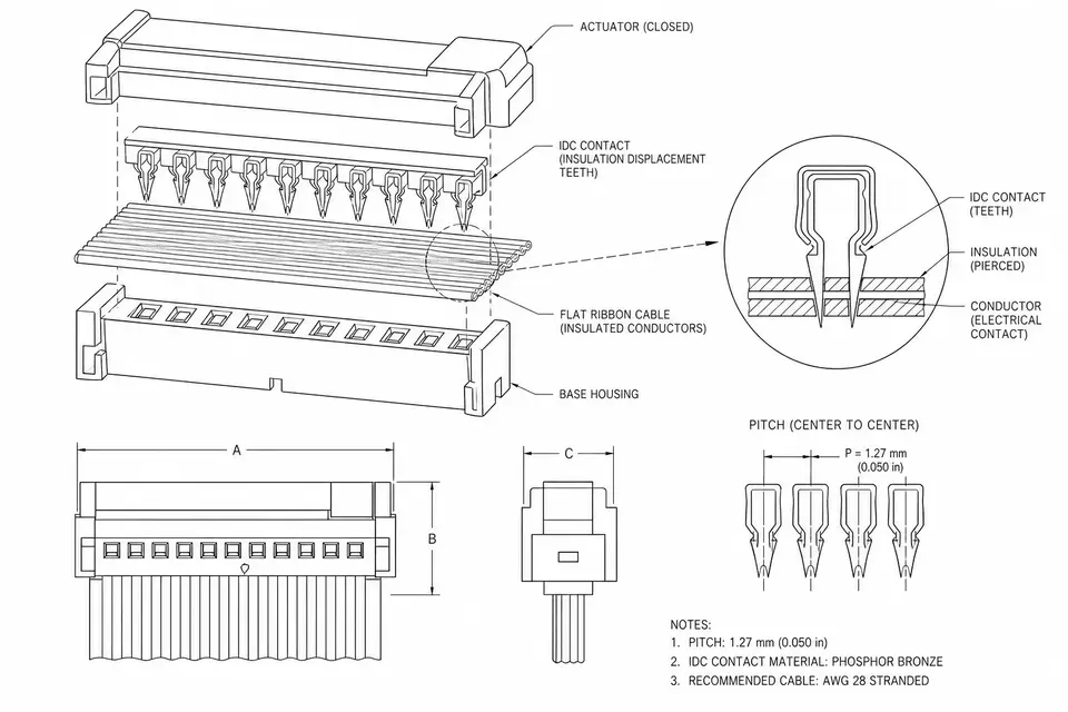
An IDC ribbon cable uses insulation-displacement contacts to terminate the parallel insulated conductors of a ribbon cable. It can simplify repeatable multi-conductor connections, but correct selection depends on the exact connector and cable combination. This guide separates con
Understand cable impedance control, compare TDR and VNA results, and define test boundaries, fixtures and report acceptance before approving an assembly.
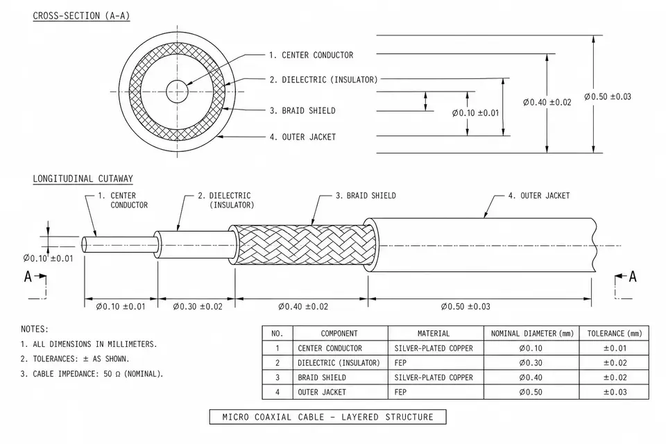
A micro-coaxial cable places a small signal conductor inside a dielectric, an outer conductor and a jacket. Selecting an assembly requires separate checks for conductor gauge, finished cable diameter, connector geometry, impedance and installed motion. This guide explains the four layers, distinguishes single-ended cable impedance from a differential pair requirement, and uses a hypothetical eight-cable row to show why AWG cannot define routing width. A six-point evidence checklist helps buyers identify missing drawings, shielding details and verification inputs before approving a substitute or requesting a quote. Manufacturer examples describe their own components, not guaranteed performance of a finished EDPcable assembly.
eDP and an LVDS-based display interface cannot be chosen from connector appearance or screen resolution alone. eDP is a DisplayPort-based internal display interface; LVDS describes an electrical signaling method used in several implementations. This guide compares their signaling