Technical Reference · LASER-STRIPPED
Micro-Coax Stripping Capability
Laser-Stripped Micro-Coax Cable Assembly Capability
Fine-AWG stripping-window control, terminal consistency, inspection checkpoints, and record support for micro-coax projects
EDPcable supports micro-coax projects where laser stripping, terminal-window control, fine-AWG handling, pre-termination inspection, and process records matter to the release. The manufacturing review connects drawings, samples, stripping windows, inspection checkpoints, and delivery records into one reviewable basis. Specific parameters, equipment settings, inspection criteria, and acceptance limits must come from customer drawings, samples, and confirmed quality files.
Quick Links
QUICK ACCESSStart with the sections closest to the project structure, interface requirements, and validation scope.

Capability Scope Snapshot
Best fit when the project already defines a micro-coax route and the main review is whether stripping windows, shield handling, dielectric protection, terminal consistency, and records can support sampling or batch release.
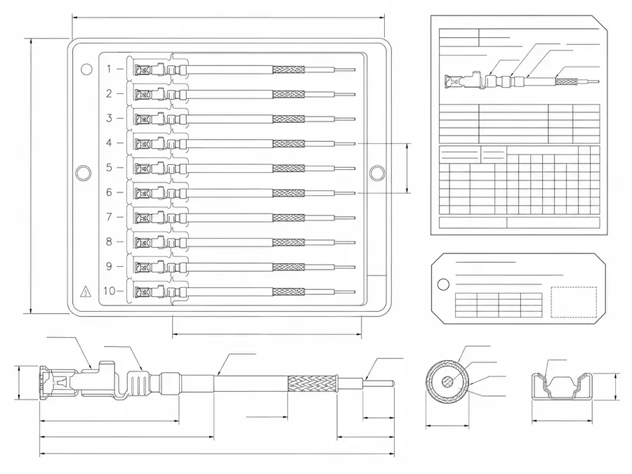
| NO | Review Item | Practical Meaning |
|---|---|---|
| 01 | Capability Definition | Laser stripping, terminal-window control, shield and dielectric handling, and inspection-record support for fine-AWG micro-coax assemblies |
| 02 | Relevant Family | Micro-coaxial cable assemblies |
| 03 | Typical Programs | 0.25mm pitch, I-PEX CABLINE-compatible, AR/VR, UAV, medical imaging, and high-shielding micro-coax programs |
| 04 | Required Inputs | AWG, OD, layer stack, stripping window, connector, termination method, inspection requirement, and sample quantity |
| 05 | Deliverable Records | Sample approval, terminal inspection record, process note, batch label, and shipment file when requested and confirmed |
| 06 | Capability Boundary | No fixed parameter, yield, unconfirmed test result, or universal material compatibility is claimed by this page |
Capability Review Inputs
Use these items as first-round review inputs so the discussion does not rely on the page label alone.
Provide AWG, OD, material layer stack, and sample information.
Provide connector, termination method, and target stripping window.
Describe terminal inspection, residue, dielectric protection, or acceptance requirements.
State project stage, sample quantity, pilot quantity, and timing target.
If records, labels, or shipment files are needed, provide format and scope early.
Process Flow
Laser-stripped micro-coax programs should split input review, sample setting, trial stripping, terminal inspection, termination validation, and batch records into visible checkpoints. The flow below is a capability-first review model, not a fixed parameter promise.
| NO | Step | Control Point | Output or Record |
|---|---|---|---|
| 01 | Requirement review | Confirm AWG, layer stack, stripping window, connector, and termination method | RFQ input checklist and engineering review notes |
| 02 | Sample definition | Lock target stripping length, shield handling, dielectric protection, and sample quantity | Sample definition or trial record |
| 03 | Trial stripping setup | Tune process boundary against material and target window | Trial note, sample photo, or inspection record |
| 04 | Terminal inspection | Check conductor, shield, dielectric, residue, and length consistency | Magnified inspection record or deviation note |
| 05 | Termination validation | Confirm whether the stripped terminal supports soldering, crimping, or connector assembly | Sample approval and terminal check |
| 06 | Batch execution | Apply the confirmed window to pilot or production builds | Batch label and process record |
| 07 | Shipment confirmation | Confirm packaging, labels, and agreed shipment documents | Shipment file, carton mark, and traceability note |
Inspection Checkpoints
Inspection should move upstream. For fine-AWG micro-coax, terminal issues are easier to control before termination than after a finished assembly fails later.
| NO | Checkpoint | What To Check | Suggested Record |
|---|---|---|---|
| 01 | Incoming material | AWG, OD, layer stack, material condition | Material batch or sample confirmation |
| 02 | Trial stripping | Window length, conductor condition, shield residue, dielectric damage | Magnified check record or sample photo |
| 03 | In-process patrol | Length consistency, residue, burrs, local deformation | Patrol sheet or deviation note |
| 04 | Pre-termination check | Whether the stripped end supports the next solder, crimp, or assembly step | Pre-termination inspection note |
| 05 | Shipment confirmation | Batch label, protective packaging, sample-to-batch correspondence | Shipment checklist and batch record |
Deliverable Records
Deliverable records must be phrased carefully. The list below shows records that can be discussed for a project; it does not mean every project receives all of them by default.
| NO | Record Type | Project Stage | Use | Boundary |
|---|---|---|---|---|
| 01 | Sample approval record | Sample stage | Confirms whether the stripping window and termination method can support later work | Customer must confirm usable sample boundary |
| 02 | Terminal inspection record | Sample or pilot | Records stripping length, residue, dielectric protection, or appearance focus | Inspection items follow drawing and quality requirements |
| 03 | Process note | Pilot or production | Supports repeat orders and process-boundary review | Does not replace customer validation |
| 04 | Batch label | Pilot or production | Supports batch matching and issue tracing | Label rules must be confirmed early |
| 05 | Shipment file | Shipment stage | Documents packing, quantity, and agreed shipment files | Does not represent unconfirmed test data |
Applicable Projects
This capability is most useful when terminal-window control is a real release risk, not when the project only needs a general micro-coax overview.
| NO | Applicable Project | How This Capability Helps | Not Suitable For Direct Promise When |
|---|---|---|---|
| 01 | 0.25mm pitch micro-coax | Fine-AWG and terminal-window control are more sensitive | Pitch, AWG, or termination method is not defined |
| 02 | I-PEX CABLINE compatible assemblies | Connector terminals and mating space are sensitive | Only a series name is known and mating data is missing |
| 03 | AR/VR near-eye display routes | Lightweight local-space constraints are tight | Device revision and route boundary keep changing |
| 04 | UAV or drone micro-coax | Lightweight, vibration, and shielding requirements overlap | Use environment and fixing method are unclear |
| 05 | Medical imaging micro-coax | Precision structure and record chain are stronger requirements | Signal, impedance, or validation standard is not defined |
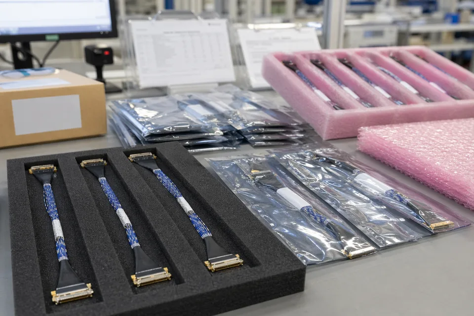
Capability Process / Records Visuals
IMAGES · 02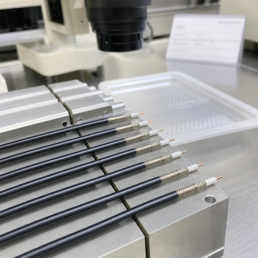
Capability process visual: micro-coax laser-stripping workstation, fixture, fine cable sample, and magnification inspection equipment
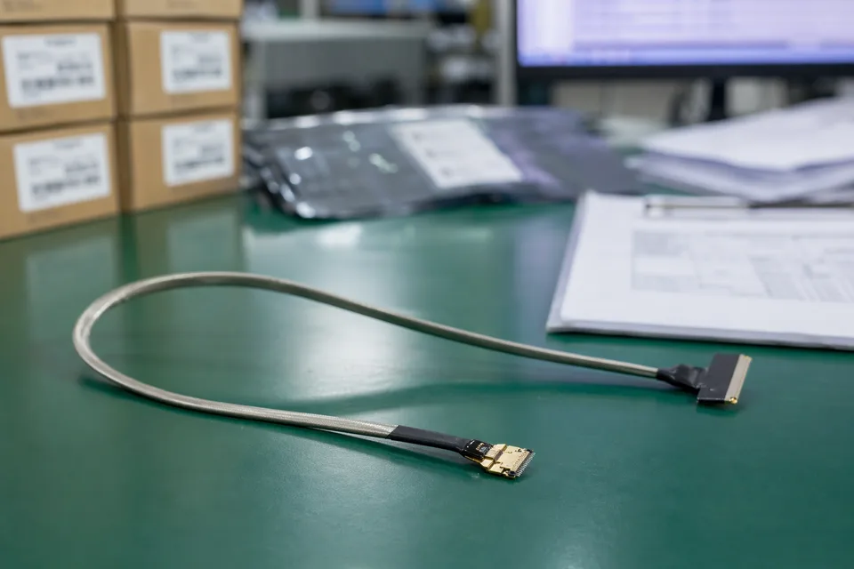
Capability records visual: stripped micro-coax terminal samples beside non-readable inspection records, batch labels, and protective tray
Process and Equipment Support
Factory information on this capability page should support stripping-window control, terminal consistency, and record evidence rather than broad scale claims.
Process and Equipment Visuals
IMAGES · 02
Laser-stripping workstation with micro-coax sample, fixture, magnifier, and non-readable process sheet
Fine terminal inspection bench with cable samples in trays and no readable equipment brand or data
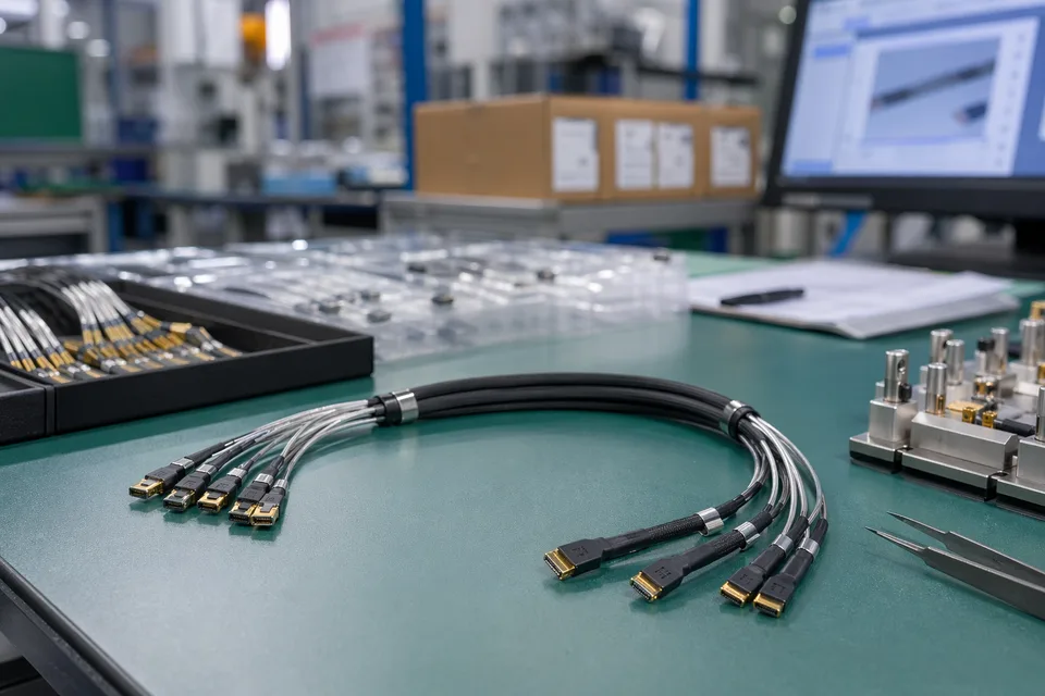
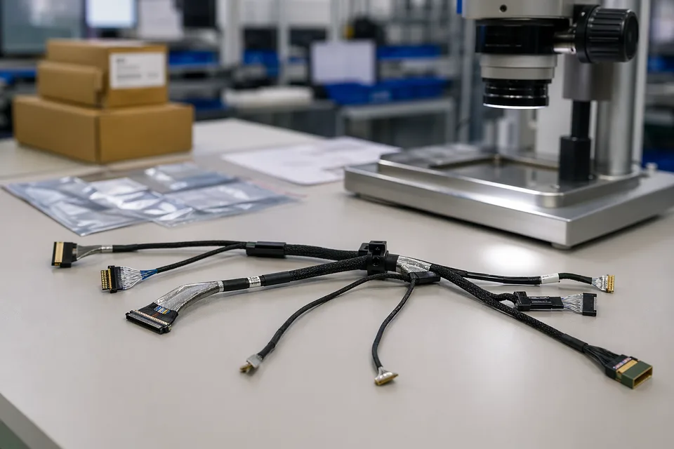
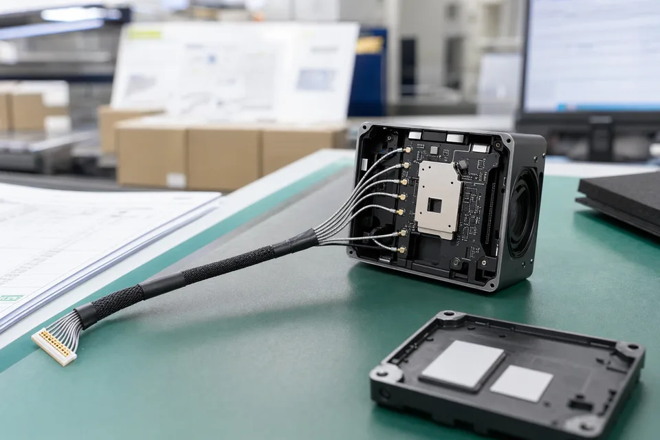
Micro-coaxial small-batch production station with shielded bundles and compact connector trays
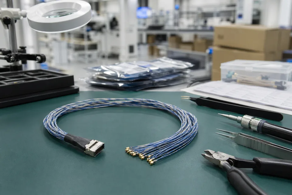
Micro-coaxial routing and termination workstation with delicate cable handling tools and ESD mat
Laser stripping and fine-AWG handling
Project review can cover jacket, shield, dielectric, conductor condition, and terminal-window needs for fine-AWG micro-coax materials.
Fixture and magnification inspection support
Small terminals can be organized with fixtures, trays, and magnified inspection to support process confirmation.
Sample-to-batch continuity
Sample window, termination method, inspection focus, and batch label should remain tied to one project definition.
Packaging and terminal protection
Packaging can be aligned to protect stripped terminals, connector ends, and fine-gauge routes when the project requires it.
Engineering, Process, and Evidence Chain
Capability review starts by defining what stripping window is needed, what termination step follows, and how the terminal will be inspected before release. Cross-family engineering review, drawing control, and documentation practice are covered in the Related Capability Pages below.
Engineering Capability
Define stripping window and termination method before treating a sample as the released basis.
Review material stack, shield handling, dielectric protection, and conductor condition together.
Quality Checkpoints
Move inspection before termination so terminal problems are visible earlier.
Do not invent yield, parameter, or acceptance claims without confirmed project evidence.
Evidence Chain
Stripping-window confirmation
Record target length, layer handling, and terminal acceptance basis before the process is carried into later samples.
Trial stripping and terminal inspection
Use sample checks, magnified inspection, or process notes to confirm the current manufacturing boundary.
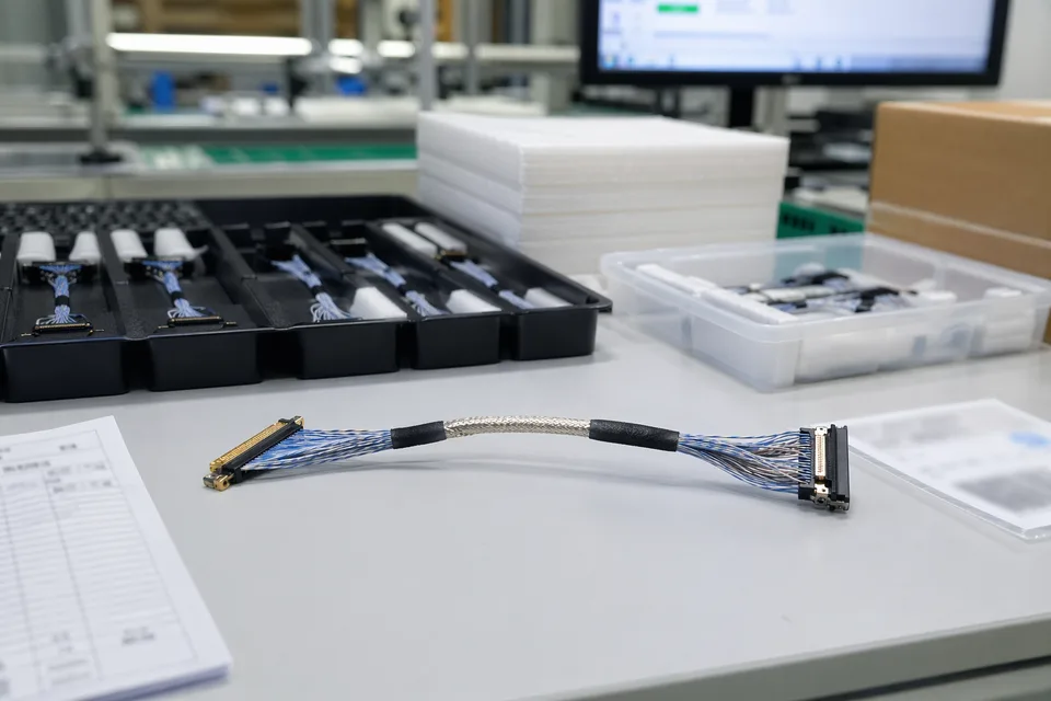
Engineering, Process, and Record Visuals
IMAGES · 02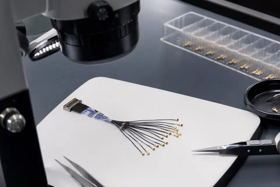
Micro-coax terminal inspection with magnification, sample tray, and non-readable process record
Stripped terminal samples, batch label, and protected tray prepared for review without fake test values
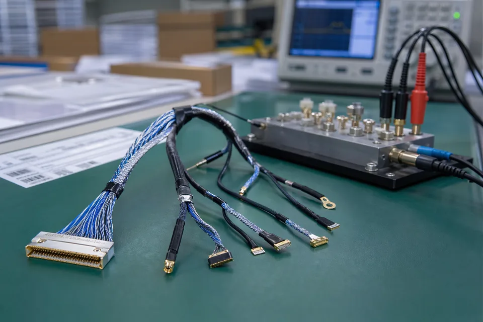
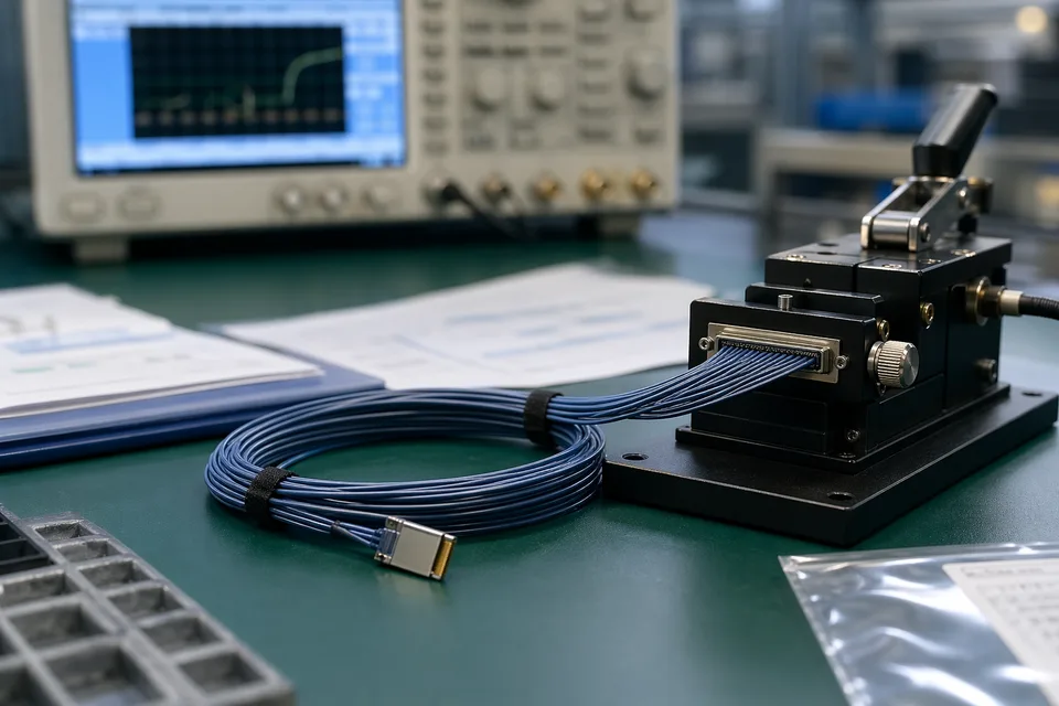
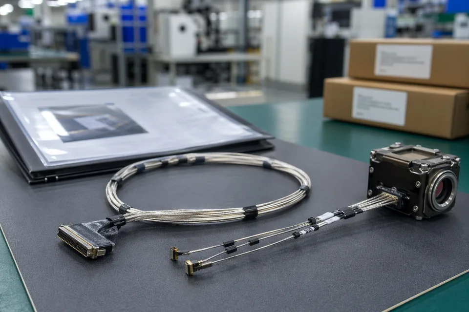
Micro-coaxial shielding and continuity test scene with fixture and compact harness sample foreground
Micro-coaxial route-fit engineering review inside compact camera or drone module mockup
Laser-Stripped Capability Project Flow
Capability projects should start from process inputs, then move through sample setting, terminal inspection, customer confirmation, and controlled batch execution.
Send process and terminal requirements
Provide AWG, material layer stack, connector, target stripping window, termination method, inspection requirement, and sample quantity.
Review capability boundary
Decide whether the material, stripping window, termination method, and record expectations fit the current process path.
Confirm quotation and sample scope
Include trial stripping, inspection, sample quantity, record depth, and timing in the quotation boundary.
Define sample and trial stripping
Run samples against the confirmed terminal window and material structure.
Inspect terminal and confirm sample
Check terminal appearance, length, and next-step termination fit before customer approval.
Execute pilot or production batch
Turn the confirmed sample boundary into batch process and inspection requirements.
Ship with traceability
Deliver using confirmed packaging, labels, and shipment-file requirements.
Laser-Stripping Capability Boundaries
The laser-stripping evidence layer captures stripping-window, material stack, and terminal-acceptance choices that are unique to this capability. Cross-family file control, batch traceability, and certification practice are summarised in the Related Capability Pages.
Process input record
Record AWG, material structure, stripping window, connector, and termination method as the process basis for this capability.
Capability boundary statement
All parameters, inspection items, and acceptance limits follow customer drawings, samples, and confirmed quality files; this page does not claim fixed parameters or universal material compatibility.
Records and Boundary Visuals
IMAGES · 02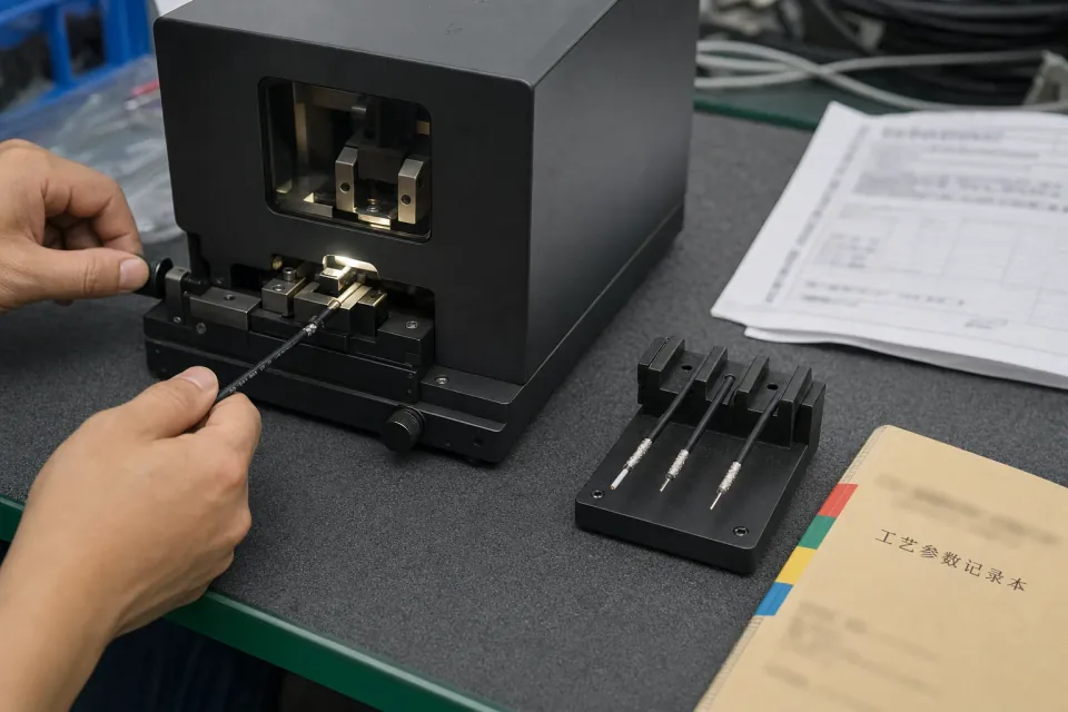
Terminal inspection records, batch labels, non-readable process sheets, and micro-coax samples in tray

Document-control scene with no fake data, no equipment logo, and no invented report values
Micro-coaxial batch traceability archive with fine connector lot labels and cable sample visible
Micro-coaxial released-sample approval folder beside shielded harness and compact module mockup
Packaging and Terminal Protection
Laser-stripped micro-coax samples need protection around stripped terminals, connector ends, and fine-gauge route sections.
Terminal protection
Anti-static bags, foam, trays, or separated packaging can be used to protect stripped terminals.
Sample and batch identification
Labels can be aligned to sample number, process revision, or batch requirement when confirmed.
Shipment-side files
Packing information, batch labels, inspection records, or agreed shipment files can be provided when scope is confirmed.
Packaging and Shipping Visuals
IMAGES · 02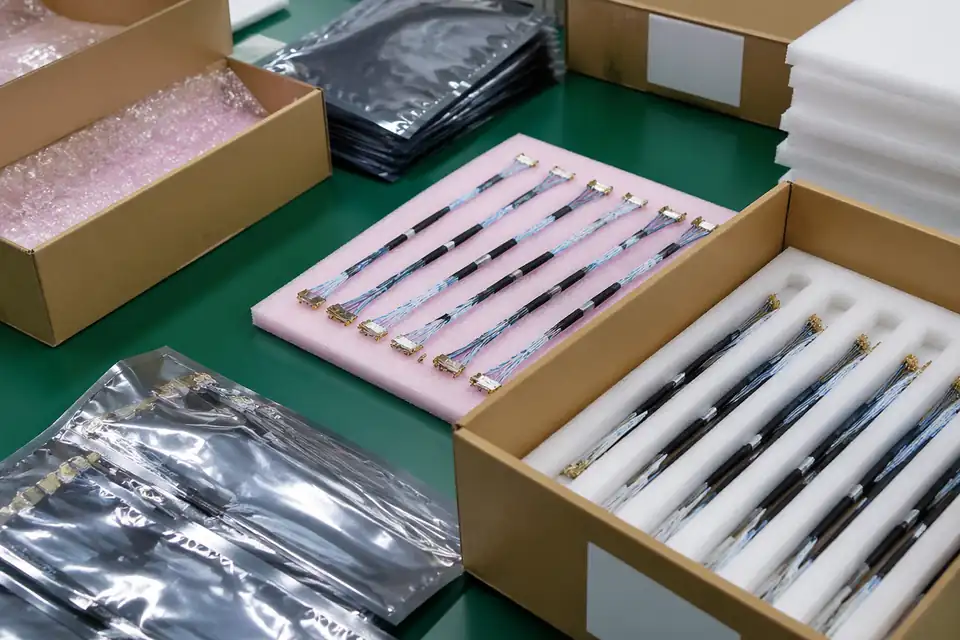
Micro-coax sample tray with anti-static bag, terminal protection, batch label, and carton
Protected fine-AWG cable shipment preparation with non-readable labels and no fake certification claims
Micro-coaxial precision sample shipment preparation with trays, foam separators, and label context
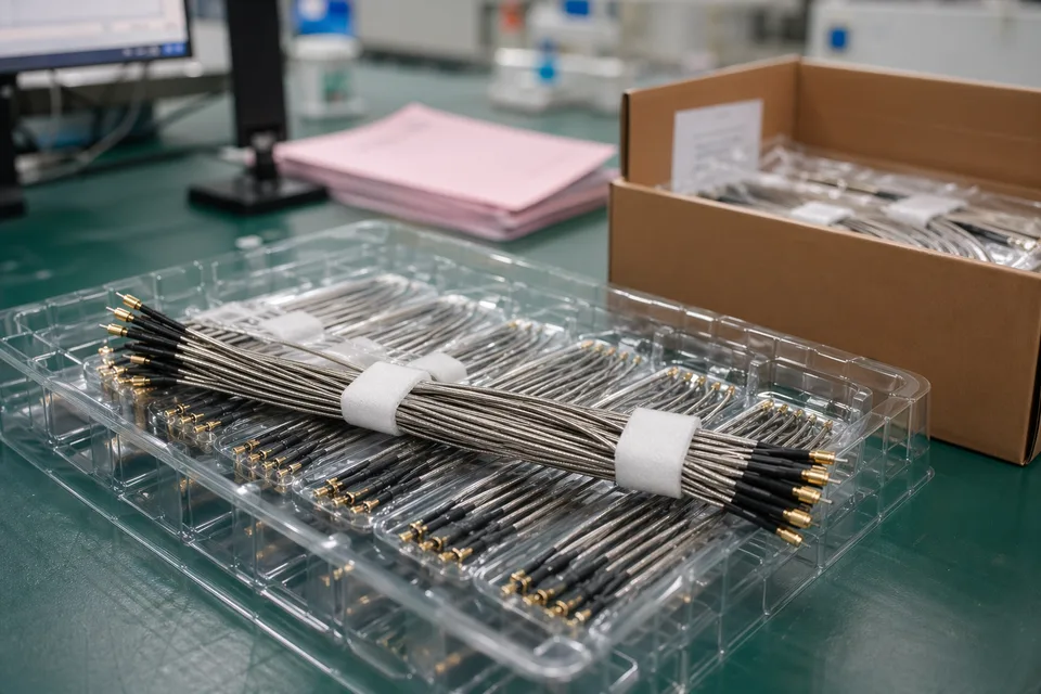
Micro-coaxial carton staging with protected fine connectors, traceability cards, and delivery support