Specification
REF-01Micro Medical Wire Harness
For compact medical harness builds and small-device routing programs.
MicroMedicalHarness
View Specification PageTechnical Reference · MEDICAL-CABLE-ASSEMBLIES
Medical Device Interconnects
Select by Device Interface, Use Environment, Motion, and Validation Scope
Use this page to define the medical interconnect family before moving to a monitoring, imaging, portable-device, probe, or sensor page. Start with the host equipment and mating connector part numbers, patient-side or internal location, route and flex duty, strain relief, cleaning exposure, materials, shielding, labels, and validation plan. These project inputs become the controlled drawing and inspection basis; suitability remains subject to device-level risk assessment and validation.
Quick Links
QUICK ACCESSUse the project interface, structure, and application requirements to move into the right content.
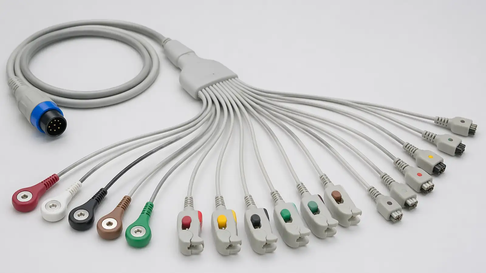
Identify the host equipment, complete mating interfaces, patient-side or internal use, motion profile, strain relief, cleaning exposure, material restrictions, record depth, and acceptance tests before selecting a cable structure. These choices separate monitoring, imaging, probe, sensor, and internal-harness paths without assuming that one medical construction fits every device.
| 01 | Quality Focus | Released drawing control, material and version traceability, agreed inspection, and batch correspondence |
| 02 | Typical Applications | Patient monitoring, medical imaging, diagnostic systems, probe assemblies, and sensor interconnects |
| 03 | Material Direction | Selected from the device location, flex duty, cleaning exposure, contact conditions, material restrictions, and approved specification |
| 04 | Compliance Context | Manufacturing records support the customer's device-level risk management, compliance assessment, and validation; the cable page does not replace them |
| 05 | Production Support | Drawing review, project-defined samples, device-side validation support, controlled release, and revision-managed supply |
| 06 | Cable Structures | Multi-core, coaxial, micro-coaxial, and hybrid structures selected for the interface, route, motion, shielding, and strain-relief needs |
| 07 | Customization | Complete connector references, pinout, length, labels, branch structure, shielding, overmold, and strain relief |
| 08 | Verification Focus | Inspection and electrical or mechanical checks defined by the released drawing, method, fixture, sample plan, and device validation scope |
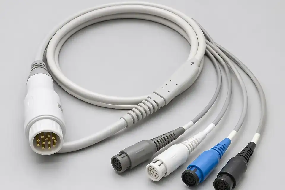
Patient-monitoring cable assembly
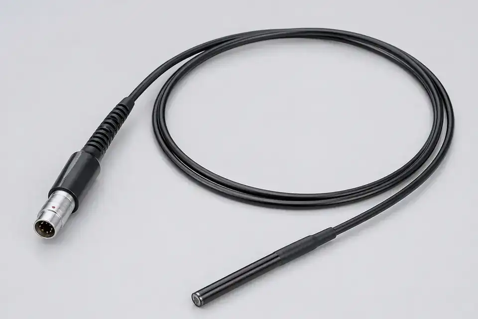
Medical-imaging interconnect detail
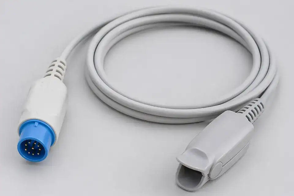
Probe or sensor cable detail
Organize connector, pin-count, pitch, routing-space, and release requirements before narrowing the manufacturing scope.
Specification
REF-01For compact medical harness builds and small-device routing programs.
Specification
REF-02For medical interconnect programs that need clean assembly discipline, inspection checkpoints, deliverable records, and traceability support.
Use device type, installed position, and validation focus to choose the matching application page.
Application
REF-01For monitoring-system cable assemblies that need repeatable connector mapping and controlled project release.
Application
REF-02For medical diagnostic systems that need stable harness integration and clearer validation support.
Application
REF-03For handheld or mobile medical equipment wiring where size, handling, and routing fit matter.
Application
REF-04For ECG trunk-cable and lead-wire programs where lead count, snap or clip termination, and color-coding conventions drive the build.
Application
REF-05For high-density fine micro-coax probe and transducer programs where element count, flexibility, and probe-end strain relief drive the build.
Application
REF-06Custom cable assemblies for single-use endoscope programs. Define camera interfaces, insertion routing, power, packaging and OEM verification before sampling.
View Application PageMedical cable review starts with device context, not a generic medical label. Interfaces, route, motion and pull loads, strain relief, cleaning exposure, materials, labeling, shielding, and record requirements must resolve into one drawing and validation boundary.
Confirm the host device, cable location, user or patient contact boundary, complete mating connector references, and applicable device revision before sampling starts.
Review route, bend or torsion duty, pull loads, strain relief, cleaning exposure, materials, shielding, labels, branch structure, and connector relationships against the device risk assessment.
Freeze connector references, dimensions, wire sequence, structure, labels, and key process notes in a controlled drawing so samples, validation, and production stay aligned.
Move into controlled production only after the drawing, sample scope, acceptance criteria, and device-side validation release are confirmed for the active revision.
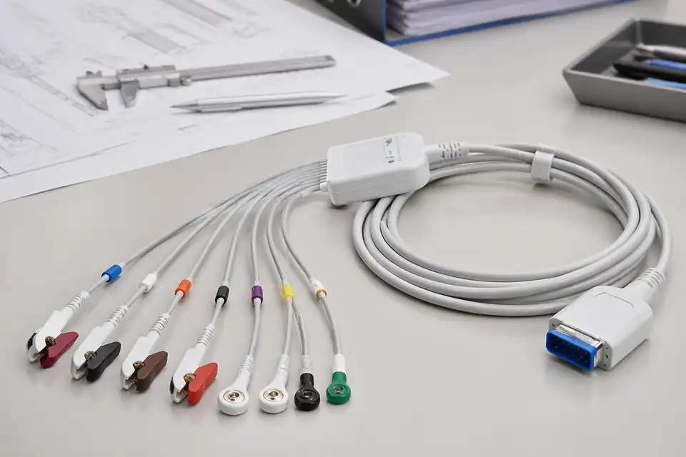
Medical engineering drawing set
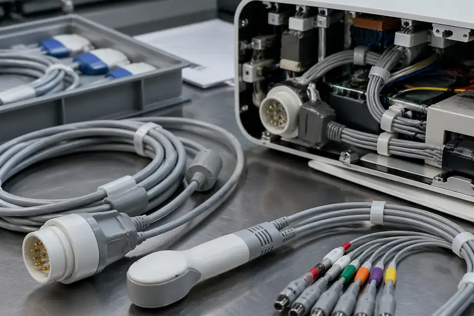
Material and use-condition review
Medical-project records must show what was built, inspected, and validated for the active device revision. Cable-level inspection supports the customer's device release, but it does not establish biocompatibility, cleanability, electrical safety, or clinical suitability outside the agreed material and validation scope.
In medical work, the issue is not only whether one sample passes, but whether repeated batches can keep the same execution standard, version stability, and project-record logic.
Inspection and test items follow the released control plan. Electrical, flex, pull, cleaning, or other reliability checks require agreed methods, fixtures, cycle or load conditions, sample quantities, and acceptance limits.
Inspection records, batch traceability, FAIR, OQC, and project-release files matter because they connect samples, drawings, batch execution, and issue tracing into one stable chain.
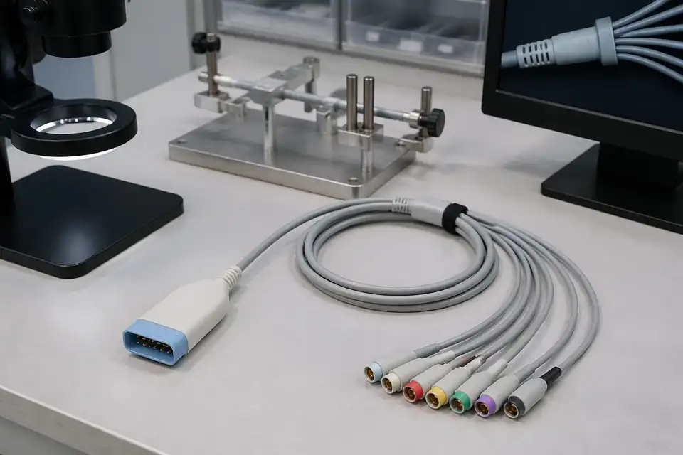
Process-record reference
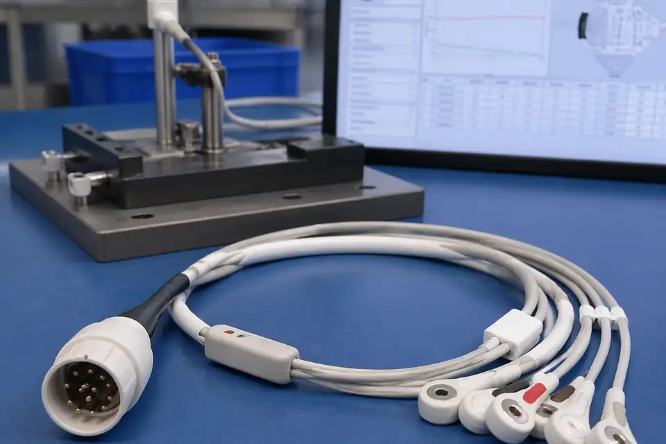
Inspection-report example
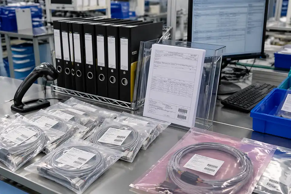
Batch-traceability and release record
Choose the next page from the cable's role in the device: an external monitoring path, an internal imaging or diagnostic route, or a moving probe or sensor interconnect.
Most medical-cable programs move through scope definition, engineering review, sample validation, and controlled production. The clearer that path is, the easier it becomes for sourcing, quality, and engineering teams to move the project forward.
Start from device type, application context, connector information, expected quantity, and current project stage so review begins from a clear scope.
Review structure, material direction, connection relationships, handling method, and manufacturability before the project moves into sample build or production.
Evaluate the installed sample against the device manufacturer's allocated risk controls, mapping, materials, cleaning or handling exposure, traceability needs, and approved acceptance plan.
Move into controlled batch production and shipment support once the structure, sample, and release logic are all clearly confirmed.