Specification
REF-01Fine-Pitch FFC/FPC
For narrow-pitch flexible interconnect programs that depend on tighter pitch control and layout fit.
FFCFPCFine Pitch
View Specification PageTechnical Reference · FFC-FPC-CABLE-ASSEMBLIES
Flexible Interconnects
Flexible Interconnect Solutions for Display Modules, Compact Devices, and OEM Programs
EDPcable manufactures custom FFC, FPC, ZIF-connected, and FPC-to-wire hybrid assemblies for flexible interconnect programs. In flexible-interconnect work, schedule risk usually comes less from one isolated parameter and more from whether pitch, connector choice, structure, reinforcement, and shielding were planned against the real device space and assembly method. Once those basics are sorted out early, drawing review, sample approval, and formal delivery stop getting trapped by the same structural details. For OEM programs that depend on compact routing, fine-pitch execution, and stable batch output, FFC / FPC is often one of the first flexible-interconnect solutions to be confirmed.
Quick Links
QUICK ACCESSUse the project interface, structure, and application requirements to move into the right content.
Before moving into detailed specification review, most teams need to confirm pitch, structure type, connector system, reinforcement method, routing space, and verification scope. This stage is less about rushing toward samples and more about checking whether the flexible-structure boundary is defined correctly.
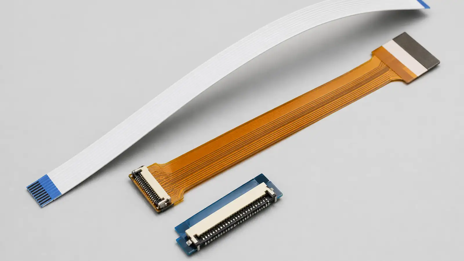
| 01 | Typical Pitch | 0.5mm, 1.0mm, and other project-specific pitch options |
| 02 | Typical Structures | FFC, FPC, and hybrid FPC-to-wire flexible interconnect structures |
| 03 | Typical Applications | Consumer electronics, display modules, compact devices, and internal flexible routing |
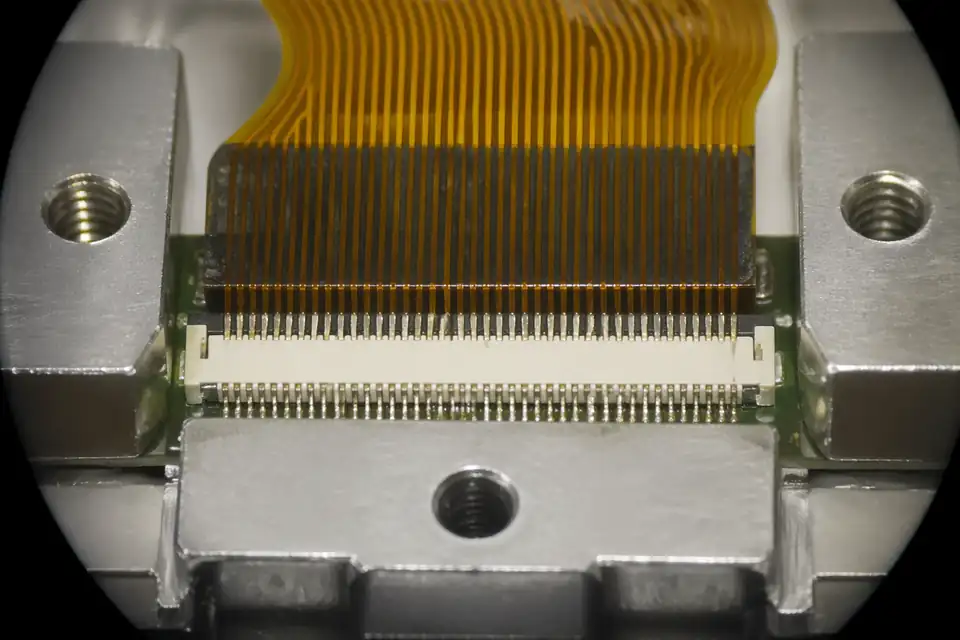
| 04 | Connector Focus | ZIF and other miniature flexible connection systems |
| 05 | Customization | Length, stiffener, EMI tape, shielding, and structure details |
| 06 | Material Direction | Structure and material selection based on environment, routing method, and assembly needs |
| 07 | Production Support | Prototype build, engineering review, pilot introduction, and OEM production support |
| 08 | Verification | Continuity, visual inspection, and structure-related checks |
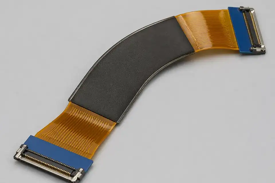
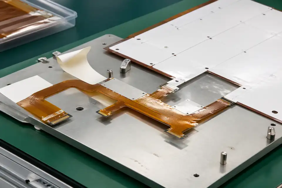
Flexible routing layout
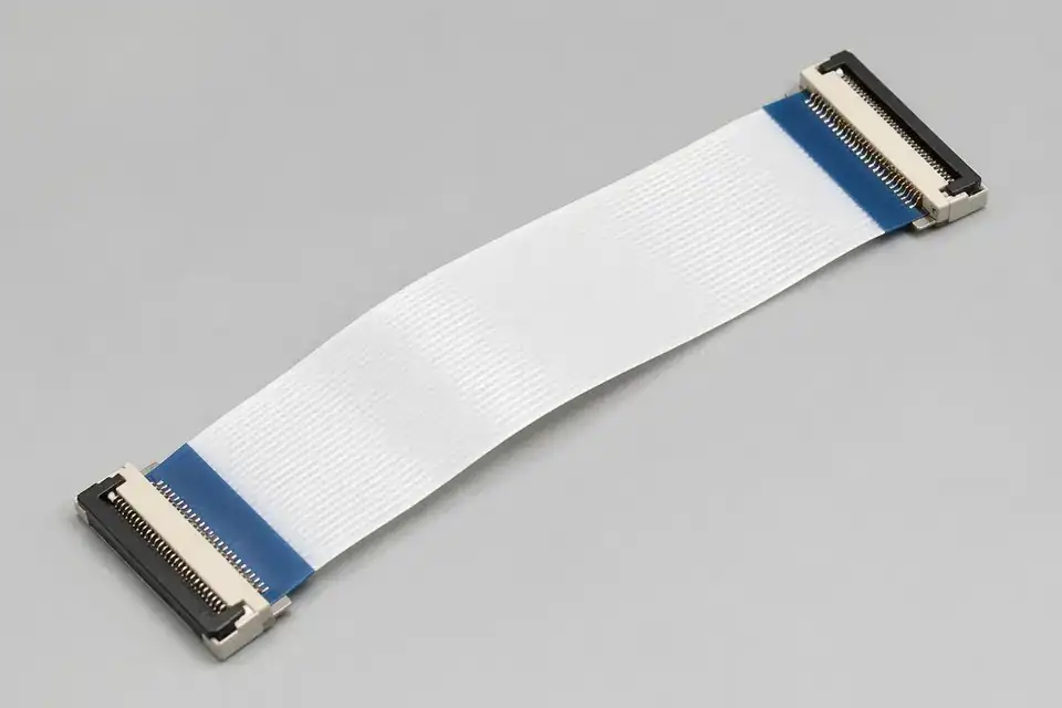
ZIF connector detail

FPC-to-wire transition structure
Organize connector, pin-count, pitch, routing-space, and release requirements before narrowing the manufacturing scope.
Specification
REF-01For narrow-pitch flexible interconnect programs that depend on tighter pitch control and layout fit.
Specification
REF-02For flexible interconnect programs where 0.5mm or 1.0mm pitch choice drives layout, connector fit, and inspection planning.
Specification
REF-03For constrained-space projects that need controlled cable folding and routing geometry.
Specification
REF-04For hybrid builds that transition from FPC pads to discrete wires and need reinforcement, strain relief, and release evidence.
Use device type, installed position, and validation focus to choose the matching application page.
Application
REF-01For small devices that need flexible internal interconnects in tighter layouts.
Application
REF-02For repeated-bend and hinge-adjacent routing programs around displays and fold zones.
Flexible-interconnect engineering usually depends less on part count than on whether pitch, connector orientation, reinforcement method, routing space, and bend definition are already settled. If those points are still in flux, samples, drawings, and process review tend to loop.
Confirm whether the project is FFC, FPC, ZIF-connected, or FPC-to-wire hybrid before sampling starts.
Review pitch, routing space, bend method, reinforcement needs, shielding structure, and installation constraints to ensure the design fits the actual device environment.
Freeze connector references, dimensions, structure, stiffener or tape requirements, and assembly notes in a controlled drawing so the review basis, sample version, and released production build stay tied to the same file set.
Move into production only after structure direction, drawing definition, and sample logic are all confirmed.

FFC / FPC engineering drawing set
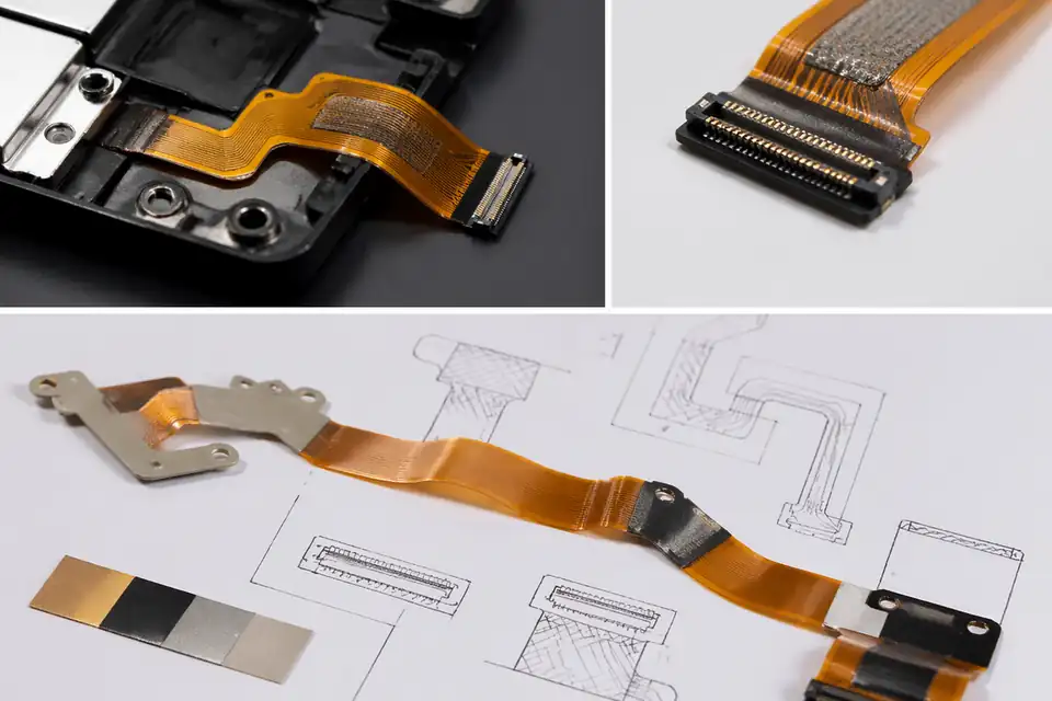
Pitch and reinforcement structure review
FFC / FPC programs usually carry tighter requirements around fine-pitch execution, structure consistency, connector fit, and batch-to-batch variation control. Rather than making broad quality claims, it is more convincing to show the real structure risks, verification items, and release criteria. Confidence comes from inspection logic, version records, and shipment output that point back to the correct released structure.
Common risks in flexible-interconnect work are not limited to continuity. They include pitch variation, stiffener drift, outlet-direction deviation, and structural instability across repeated builds.
Continuity and visual inspection are only the starting point. Structure fit, connector engagement, reinforcement execution, and project-specific validation all need to be confirmed clearly.
The relationship between controlled drawings, inspection records, and sample definition is what determines whether batch production stays stable and whether repeat orders become easier to support.
Fine-pitch inspection detail
Released-structure record
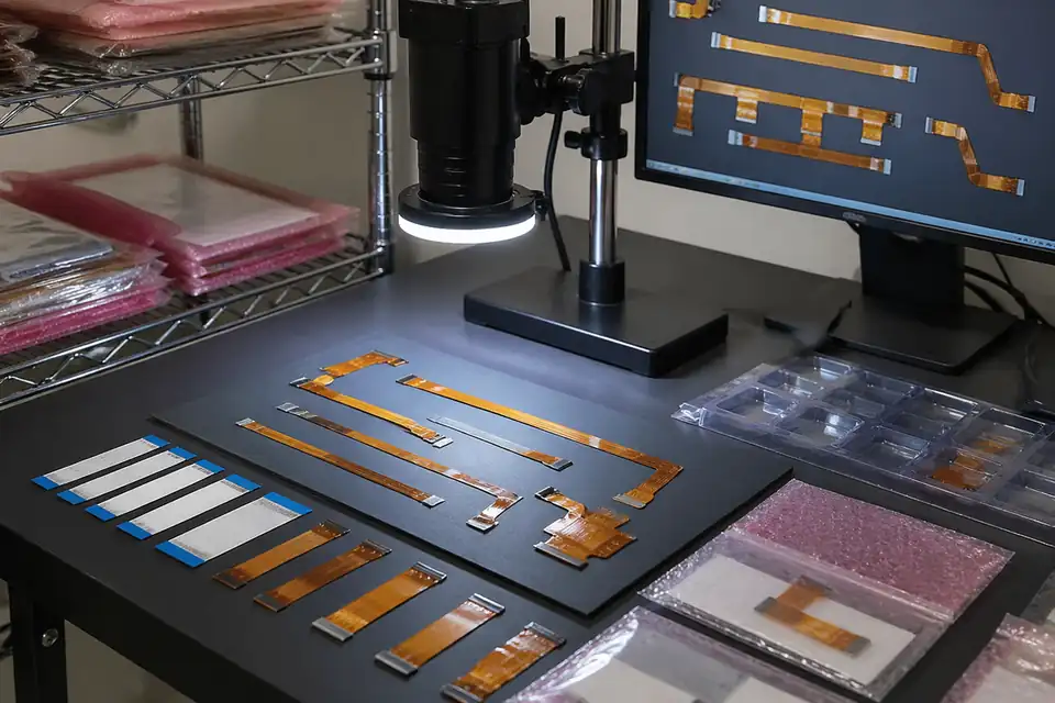
Batch verification reference
Compact display modules, consumer-electronics assembly, and hybrid FPC-to-wire structures are three of the most common flexible-interconnect program types. Each one places a different emphasis on engineering, quality, and delivery.
Most flexible-interconnect programs move through scope definition, structure review, sample validation, and controlled production. When the required inputs, review gates, and release points are defined early, sourcing and engineering teams can move faster internally.
Start from pitch, structure direction, connector references, application layout, and expected quantity so technical review begins from a clear scope.
Review routing, pitch, connector system, reinforcement design, and manufacturability before the project moves into sample build or production.
Use drawing confirmation, sample build, and project-side evaluation to confirm that the structure is suitable for formal release.
Move into controlled production and shipment support once the structure direction, drawing logic, and validation path are clear.