Specification
REF-0130-Pin eDP Cable Assemblies
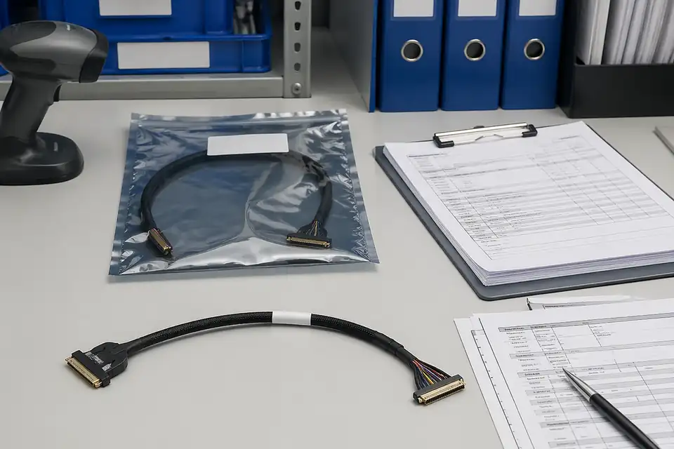
For common laptop and compact-display programs that need a clear 30-pin internal display interconnect route.
30-PinDisplay100 Ohm
View Specification PageTechnical Reference · EDP-CABLE-ASSEMBLIES
High-Speed Display Interconnects
30-Pin & 40-Pin eDP Cable Solutions for OEM Display Programs
EDPcable manufactures custom eDP cable assemblies for laptop, tablet, industrial display, and medical display programs. In projects like these, the first question is rarely one isolated parameter. What matters first is whether the interface definition is clear, whether the 30-pin or 40-pin path is correct, whether the routing and shielding structure fit the device layout, and whether samples, drawings, and production can stay aligned under one controlled definition.
Quick Links
QUICK ACCESSUse the project interface, structure, and application requirements to move into the right content.
Before moving into detailed specification review, most teams need to confirm the pin range, connector system, routing logic, shielding expectations, and verification scope. The clearer that scope is, the smoother the sample and release process becomes.
| 01 | Common Pin Counts | 30 Pin / 40 Pin |
| 02 | Typical Applications | Laptop displays, tablets, industrial displays, medical displays |
| 03 | Connector Systems | I-PEX and other mainstream display connector families |
| 04 | Signal Focus | Internal display interconnects that require stable differential transmission and controlled routing |
| 05 | Impedance Target | 100 Ohm differential routing and matching focus |
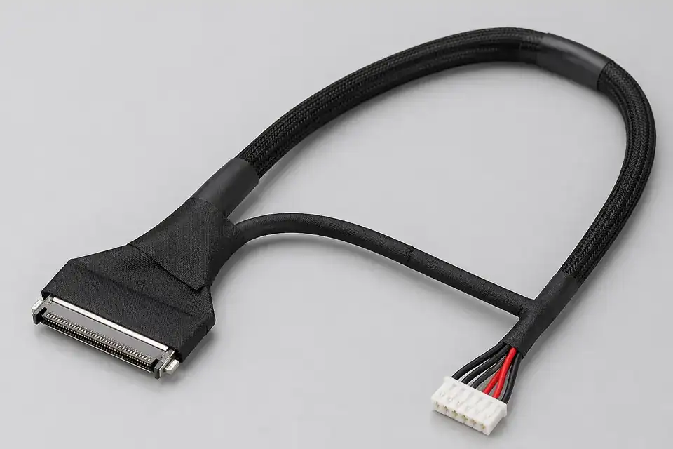
| 06 | Cable Structure | Custom eDP display interconnect structures based on project layout and installation space |
| 07 | Shielding Options | Project-based shielding and EMI control options |
| 08 | Length | Custom length based on device layout |
| 09 | Verification | Continuity, insulation, visual inspection, and impedance-related checks |
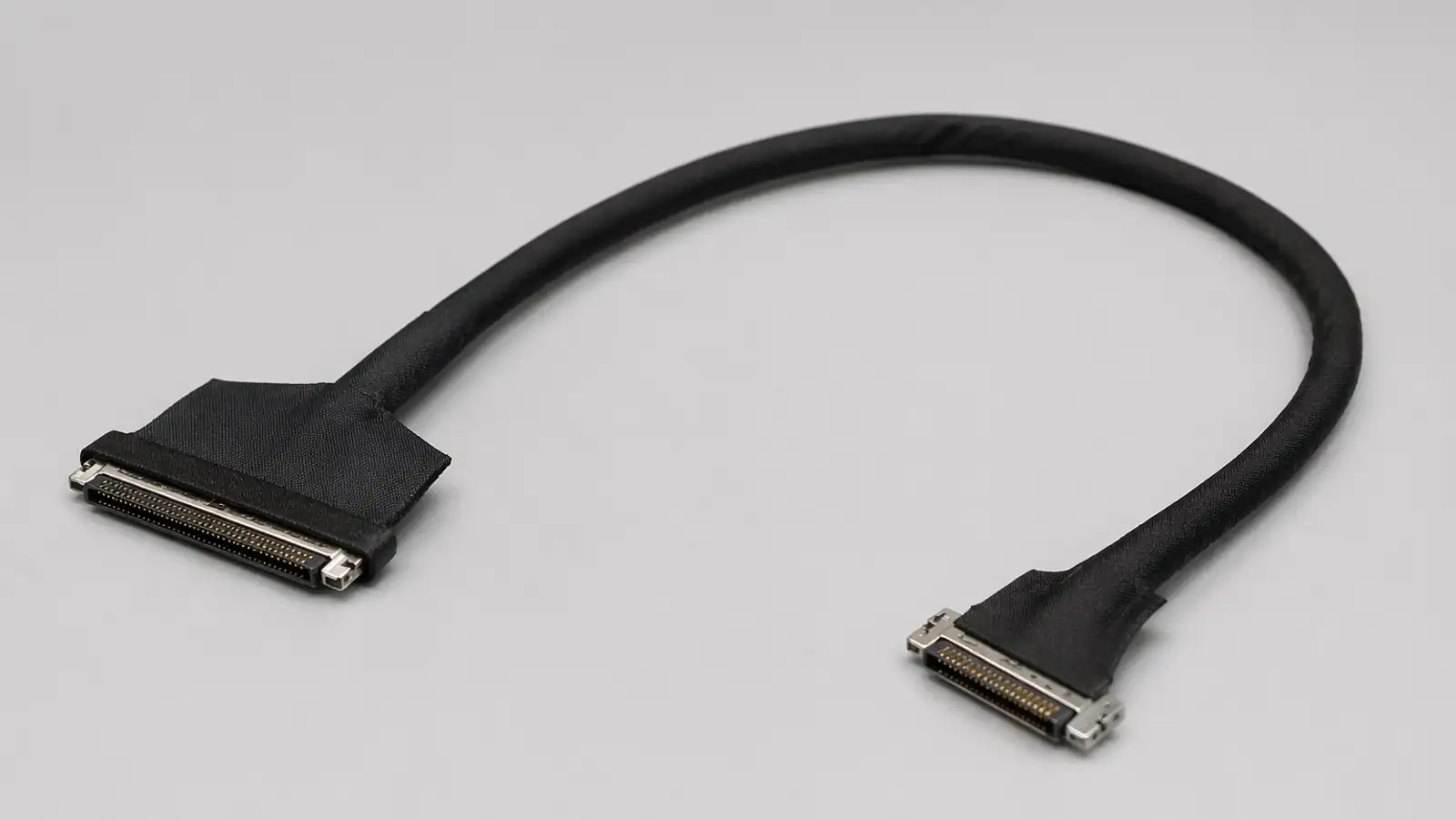
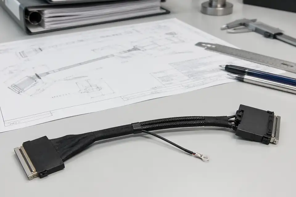
eDP connector-system detail
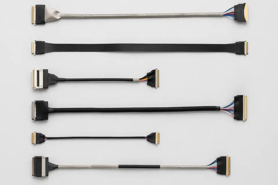
30-pin and 40-pin assembly comparison
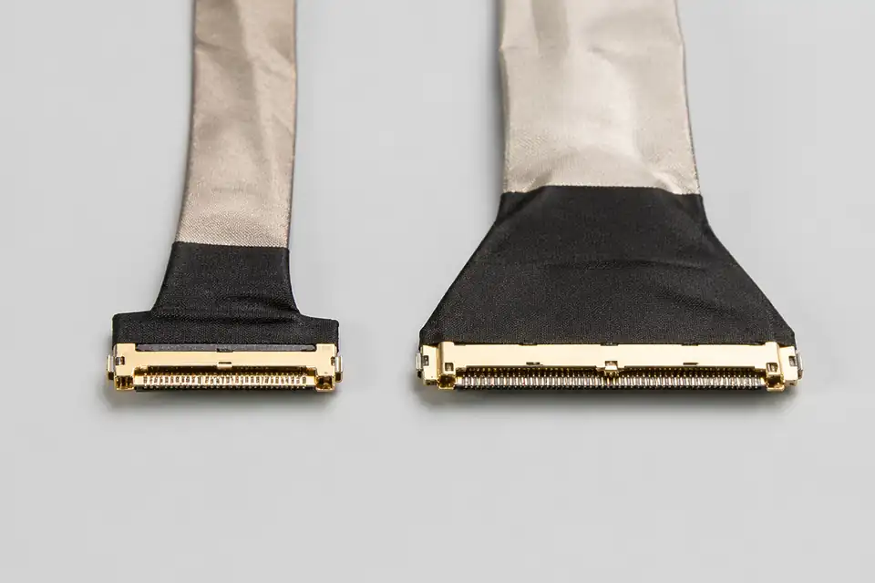
Display-link routing and shielding detail
Organize connector, pin-count, pitch, routing-space, and release requirements before narrowing the manufacturing scope.
Specification
REF-01For common laptop and compact-display programs that need a clear 30-pin internal display interconnect route.
Specification
REF-02For higher-pin-count eDP projects where routing space, shielding control, and repeatable termination matter.
Specification
REF-03For projects that already know the connector family and need a tighter connector-matching review.
Use device type, installed position, and validation focus to choose the matching application page.
Application
REF-01For display-side wiring in medical equipment where stable structure, clear release logic, and validation support matter.
Application
REF-02For industrial monitor and module programs that prioritize shielding consistency and installation fit.
Application
REF-03For internal display harness programs that depend on predictable batch consistency and faster engineering confirmation.
eDP projects usually carry more engineering sensitivity than ordinary cable builds. What matters is not only whether the assembly connects, but whether the interface definition, routing path, shielding structure, and bend space are clear enough to support a controlled drawing release and repeatable production.
Confirm 30-pin or 40-pin requirements, connector references, pin definitions, device layout constraints, and routing direction before sample release.
Assess shielding structure, cable length, bend space, fixing method, and installation environment so the design is not only buildable, but also repeatable in production.
Freeze dimensions, pin mapping, connector references, material notes, and process-critical requirements in a controlled drawing so the approved sample and the production build stay aligned.
Move into sample or production only after the drawing logic, structure definition, and release requirements have all been confirmed.
eDP engineering drawing set
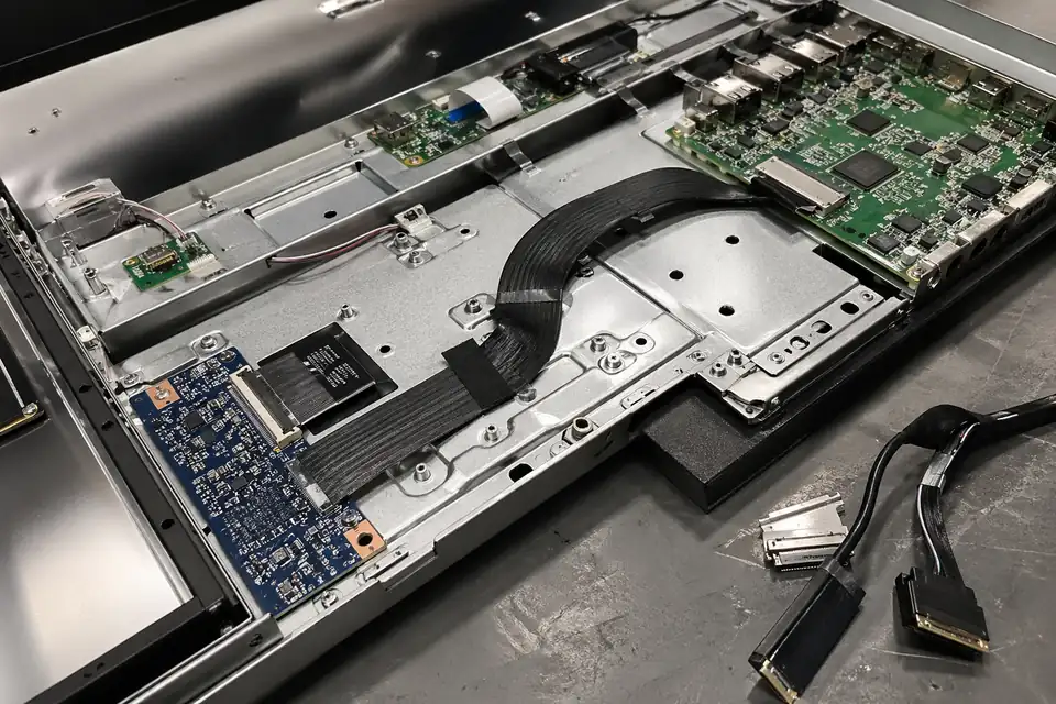
Connector mapping and installation-space review
eDP programs usually carry tighter requirements around signal stability, termination consistency, and repeatable batch output. Broad quality claims are less persuasive than stable structure execution, repeatable termination quality, and production builds that stay aligned with the approved sample.
The main risks in eDP work are not abstract defect rates, but wrong pin mapping, unstable shielding execution, jacket damage, weak termination repeatability, and stress concentrated around bend-critical zones.
Continuity alone is not enough. Insulation, impedance-related control, visual workmanship, and the consistency of the approved structure under a real release path all need to be verified clearly.
FAIR, OQC reports, test reports, and conformance records matter because they tie each shipped batch back to the approved drawing, sample definition, and production requirements.
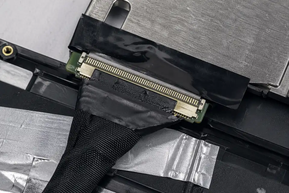
Termination and shielding workmanship detail
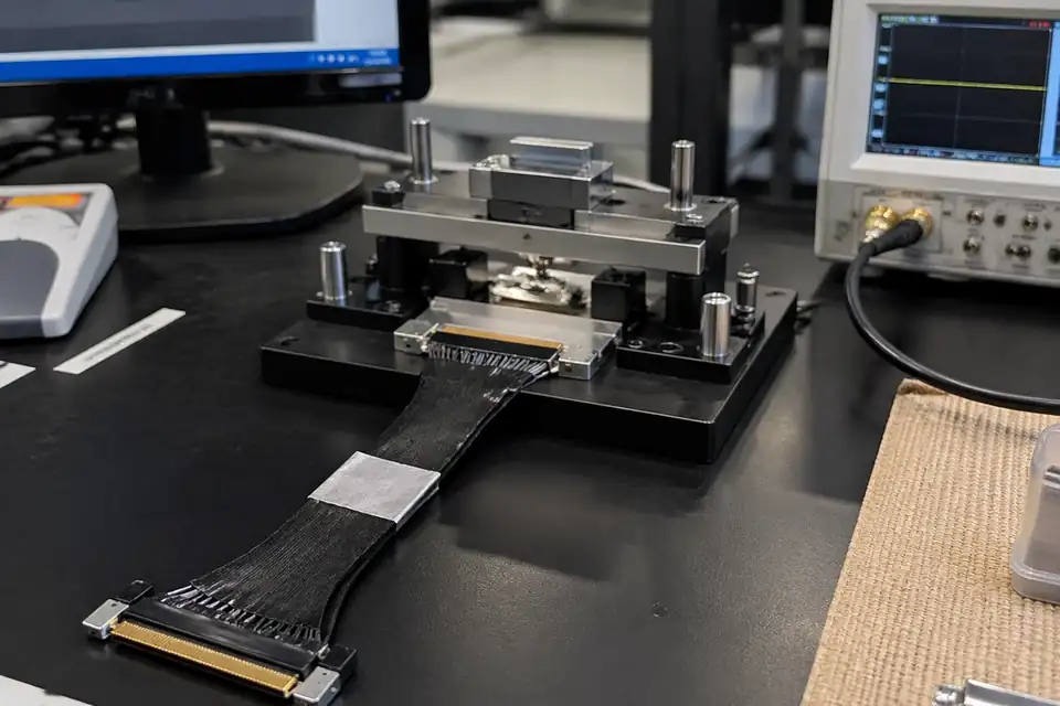
Inspection record and impedance-check reference
Released-sample traceability record
Industrial display modules, medical display equipment, and laptop or tablet interconnects are three of the most common eDP project types. Each one places a different emphasis on engineering, quality, and delivery.
Most eDP projects move through inquiry, engineering review, sample validation, and controlled production. The clearer that path is, the easier it becomes for sourcing and engineering teams to move the project forward.
Start with connector model, pin definition, target length, application context, and expected quantity so technical review begins from a clear scope.
Review interface logic, structure, routing environment, shielding expectations, and manufacturability before the project moves into sample build or production.
Use drawing confirmation, sample build, and project-side review to confirm that the structure is valid before production volume is approved.
Move into controlled production, final inspection, and shipment support under the approved definition, with the relevant quality records tied back to the released build.