Technical Reference · RF-IMPEDANCE-TESTING
Micro-Coax RF Testing Capability
Micro-Coax RF Impedance and High-Speed Signal Testing Capability
TDR, VNA, termination consistency, and sample review records for 50 ohm, 75 ohm, and 100 ohm micro-coax programs
EDPcable supports micro-coax cable assembly projects that need characteristic impedance checks, TDR time-domain reflection review, VNA-based response checks when required, termination consistency verification, and customer-facing records. When impedance, routing, and termination requirements are clear, samples, testing equipment, test records, and batch identity can be tied back to one released drawing basis.
Quick Links
QUICK ACCESSStart with the sections closest to the project structure, interface requirements, and validation scope.
Capability Scope Snapshot
Best fit when the system side already defines target impedance, allowed tolerance, and termination structure. Early-stage programs still evaluating the impedance target or cable structure should define those boundaries first.
| NO | Review Item | Practical Meaning |
|---|---|---|
| 01 | Capability Definition | Micro-coax impedance testing, TDR time-domain reflection checks, VNA frequency-domain response checks, and termination consistency verification |
| 02 | Relevant Family | Micro-coaxial cable assemblies, with overlap into LVDS and high-speed FFC/FPC review when required |
| 03 | Typical Programs | 50 ohm micro-coax, 75 ohm video, 100 ohm differential, medical imaging, AR/VR, and high-speed patch projects |
| 04 | Required Inputs | Target impedance and tolerance, test frequency or method, termination type, sample quantity, and sampling ratio |
| 05 | Deliverable Records | Sample impedance report, termination consistency record, batch sampling report, and raw TDR/VNA data when agreed |
| 06 | Capability Boundary | No fixed impedance value, yield, or full-band response is claimed without confirmed project evidence and test conditions |
Capability Review Inputs
Use these items as first-round review inputs so the discussion does not rely on the page label alone.
Provide target impedance and allowed tolerance.
Define TDR, VNA, frequency range, or other test method expectations.
Include termination type, connector interface, and sample quantity.
State sampling ratio expectations for sample, pilot, and production stages.
Describe report format, raw-data handoff, and timing requirements.
Customer Pain Points
RF-sensitive micro-coax programs need more than a working sample. They need a test boundary that connects impedance targets, fixtures, termination condition, records, and later batch sampling.
Process Flow
Impedance testing should move through requirement review, fixture preparation, sample testing, termination consistency review, production sampling, deviation handling, and shipment records.
| NO | Step | Control Point | Output or Record |
|---|---|---|---|
| 01 | Test requirement review | Impedance target, tolerance, frequency range, and termination type | Test input checklist |
| 02 | Fixture preparation | Match fixture and interface to the cable termination | Fixture note |
| 03 | Sample testing | TDR or VNA sample test according to scope | Sample impedance record |
| 04 | Termination consistency | Compare multiple pieces in the same batch or sample set | Termination consistency record |
| 05 | Production sampling | First/last piece or agreed sampling ratio | Sampling report |
| 06 | Deviation handling | Return to process review if results move outside the agreed window | Process review record |
| 07 | Shipment confirmation | Include agreed reports with shipment documents | COC and test report |
Inspection Checkpoints
The check point is not just whether a curve appears on a screen. Test method, fixture condition, termination consistency, and acceptance window must be clear before results can support release.
| NO | Checkpoint | What To Check | Boundary |
|---|---|---|---|
| 01 | Sample TDR | Impedance curve against agreed tolerance | Frequency and setup follow the project agreement |
| 02 | Sample VNA, if applicable | S-parameter response | Higher frequency ranges require suitable fixtures |
| 03 | Termination consistency | Comparison across pieces or ends | Sampling ratio follows project definition |
| 04 | Production sampling | First/last pieces and extra checks when abnormal | Does not replace customer system-level verification |
Deliverable Records
Reports and raw data should identify sample number, test condition, acceptance window, and the drawing or revision being checked.
| NO | Record Type | Use | Boundary |
|---|---|---|---|
| 01 | Sample impedance report | Sample release support | Test conditions travel with the report |
| 02 | Termination consistency record | Evidence of same-batch variation | Acceptance follows customer criteria |
| 03 | Production sampling report | Batch release support | Sampling ratio follows agreement |
| 04 | Raw TDR/VNA data, if applicable | Customer internal review | File format is agreed project by project |
| 05 | COC | Batch release | Not a third-party certification |
Applicable Projects
Use this capability when signal performance evidence is part of the release boundary, not when the project only needs a general micro-coax overview.
| NO | Applicable Project | Typical Impedance Concern | Review Focus |
|---|---|---|---|
| 01 | Medical imaging video assemblies | 75 ohm video path stability | Test report, fixture condition, and batch sampling |
| 02 | AR/VR headset signal routes | High-density signal route consistency | Termination repeatability and shielding context |
| 03 | Industrial camera micro-coax | 50 ohm RF path review | Connector interface and TDR curve boundary |
| 04 | Data center differential routes | 100 ohm differential stability | Sampling strategy and batch records |
| 05 | Replacement programs | Old sample impedance confirmation | Reverse definition and released drawing linkage |
RF Test Workstation Support
EDPcable keeps RF testing stations separate from routine assembly work so testing does not interrupt normal production rhythm. Instrument model, frequency range, and calibration cycle are confirmed by project stage.
Factory / Production Visuals
IMAGES · 04
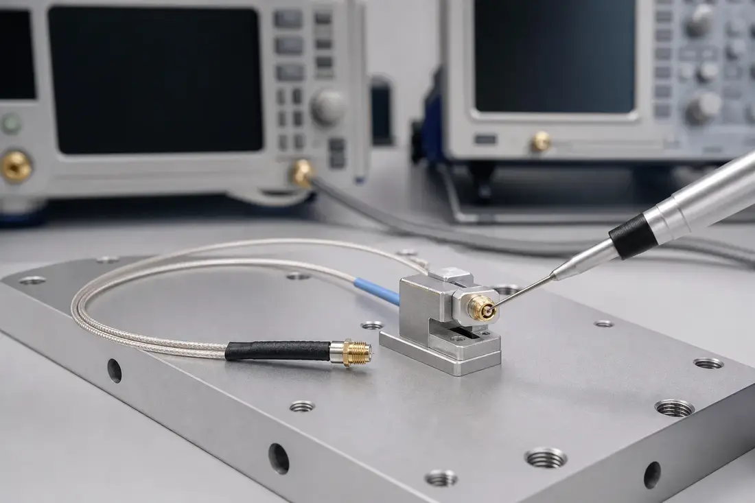
Micro-coaxial samples, fixture, and fine-assembly workstation
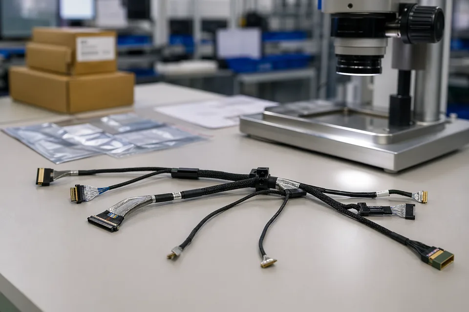
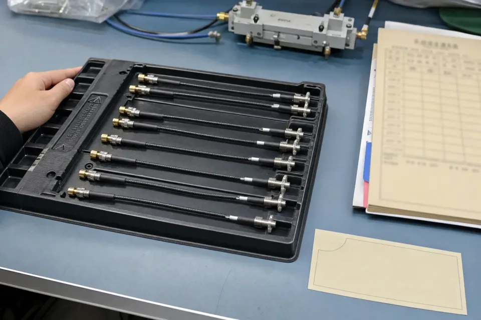
Sample harnesses, fixture, and packaging-preparation bench
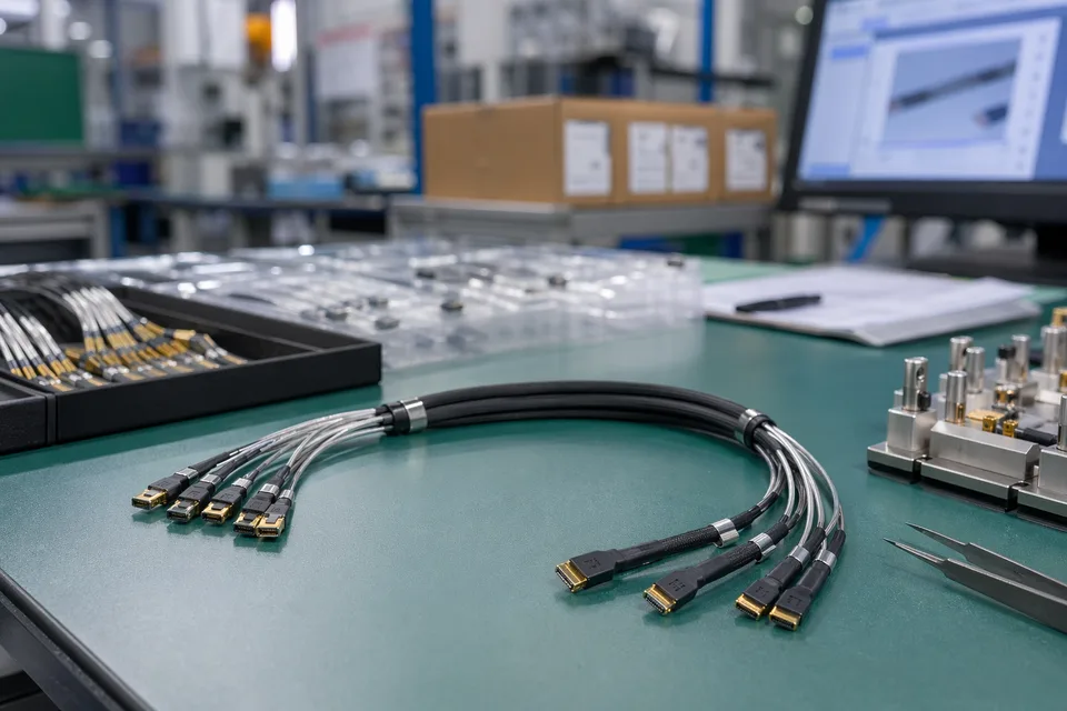
Termination fixture and harness-consistency check
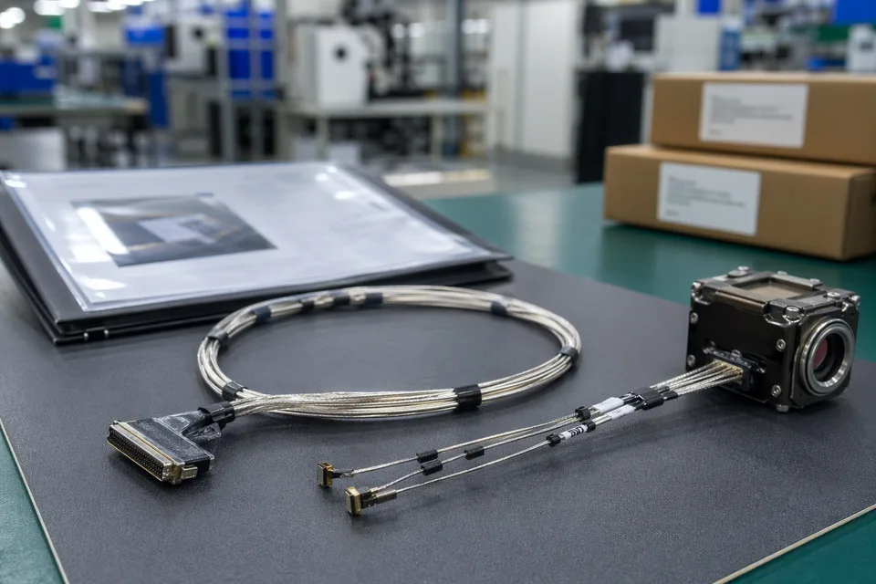
Finished assembly organization, protective packaging, and shipment preparation
TDR test support
TDR checks can support characteristic impedance review when the target and tolerance are confirmed.
VNA support when required
VNA response checks can be discussed when the project requires frequency-domain evidence and suitable fixtures are available.
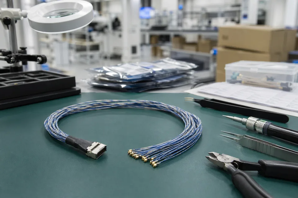
Termination consistency review
Multiple pieces or ends can be compared to judge whether termination execution is stable enough for the release.
Production sampling rhythm
First/last piece or agreed sampling ratios can be linked to production batches when the project scope requires RF evidence.
Engineering Capability
RF testing value comes from connecting the impedance target, micro-coax selection, termination method, fixture setup, and acceptance window before results are treated as release evidence. Cross-family engineering review, drawing control, and documentation practice are covered in the Related Capability Pages below.
Engineering Capability
Review impedance target against micro-coax selection and termination method before sampling.
Check whether test fixture and interface may introduce reflection that hides the true cable result.
Quality and Verification Highlights
Compare termination consistency before blaming the cable route or fixture alone.
Avoid fixed frequency, yield, or full-band claims unless the project scope and evidence support them.
Evidence Chain
Sample impedance report
Records sample number, method, setup, acceptance window, and result boundary for customer review.
Termination consistency record
Compares multiple samples or ends to show whether termination execution is stable enough for the program.
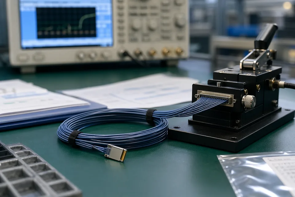
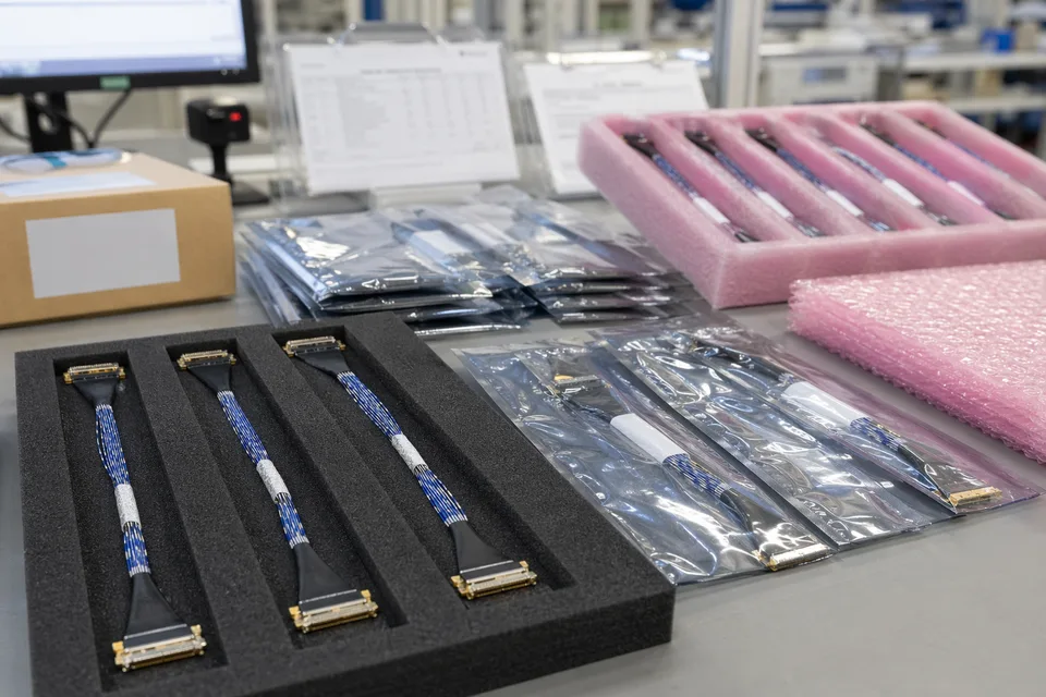
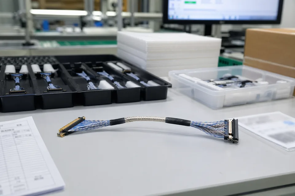
Engineering, Test, and Record Visuals
IMAGES · 02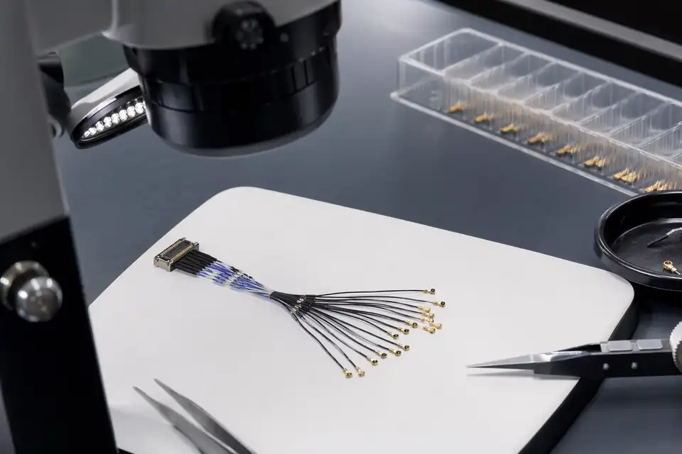
Micro-coax sample connected to TDR/VNA fixture with non-readable impedance screen and no equipment logo
Test report, batch label, and cable samples arranged for review without fake values
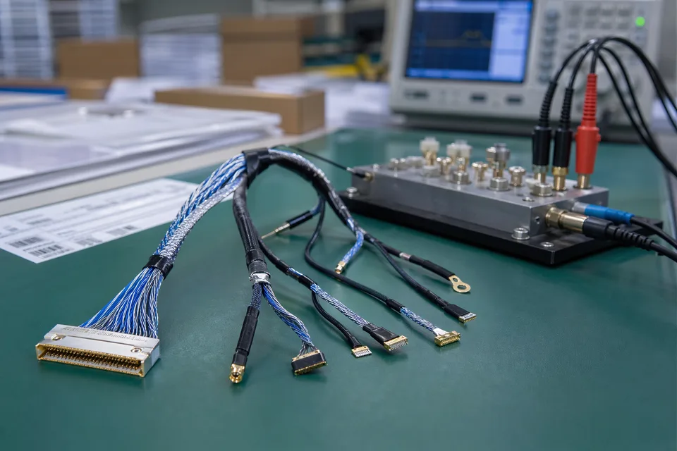
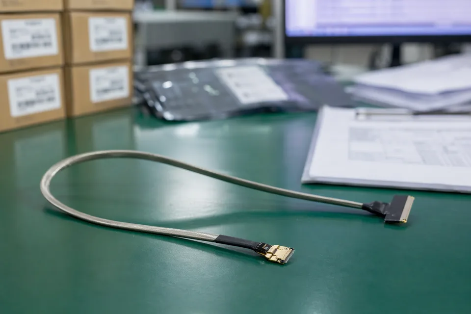
Micro-coaxial shielding and continuity test scene with fixture and compact harness sample foreground
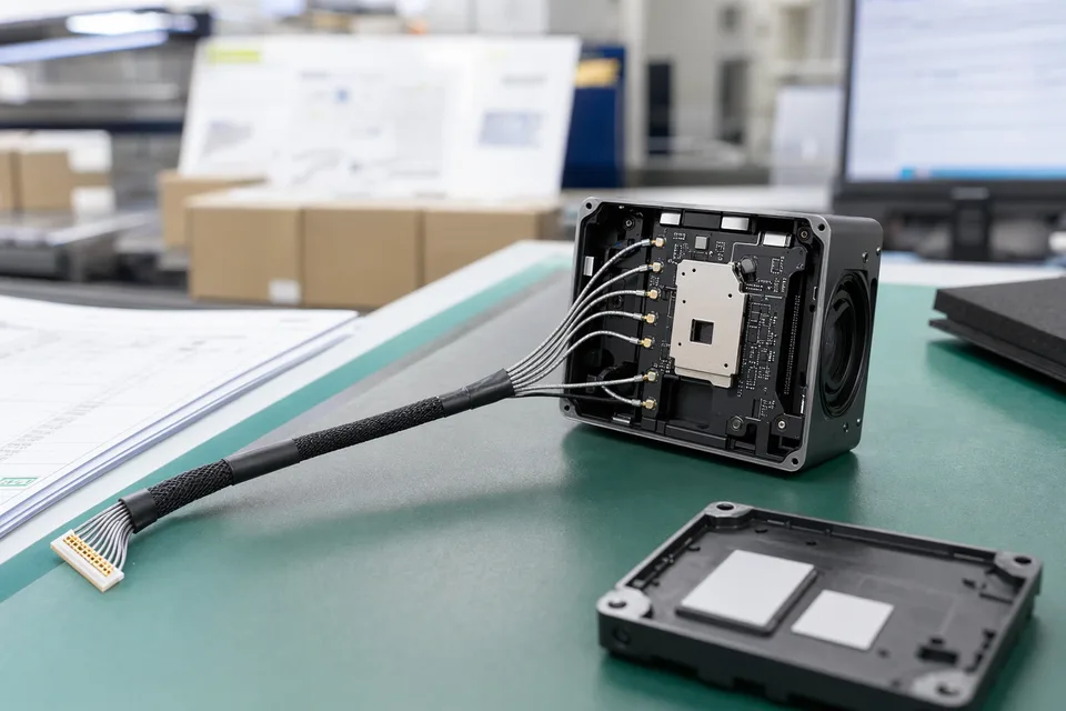
Micro-coaxial route-fit engineering review inside compact camera or drone module mockup
RF Testing Project Flow
RF testing projects should define the test boundary before samples are treated as evidence. The flow below keeps testing, records, and batch identity aligned.
Send test requirements
Provide target impedance, tolerance, test frequency or method, termination type, sample quantity, and desired sampling ratio.
Review test boundary
Confirm whether TDR, VNA, fixture, and report expectations fit the project scope.
Confirm quotation and sample scope
Align test quantity, raw-data needs, report format, and timing in the quotation boundary.
Prepare samples and fixtures
Match sample termination and fixture setup before measuring results.
Run sample and consistency checks
Check sample impedance and compare termination consistency against the agreed window.
Execute production sampling
Apply first/last piece or agreed sampling rules during batch production.
Ship with reports
Deliver agreed reports, COC, labels, and shipment files with the batch.
RF Testing Boundaries
The RF-specific evidence layer captures impedance/TDR/VNA records and testing boundaries that are unique to this capability. Cross-family file control, batch traceability, and certification practice are summarised in the Related Capability Pages.
Sample impedance test report
Supports sample approval with the agreed method, setup, and acceptance window.
Raw TDR or VNA data
Can be provided when file format and data handoff are agreed before testing.
Certifications / Records Visuals
IMAGES · 03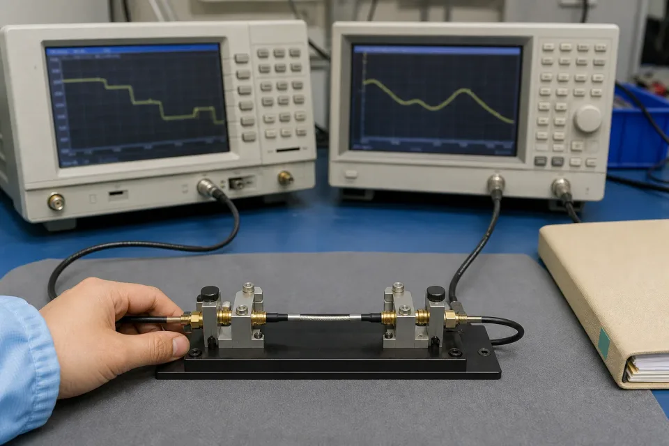
RF Impedance & High-Speed Testing certificate, quality-system, or compliance-document visual
Sample approval, inspection, or key verification record visual
Batch label, carton mark, or released-version file visual
Micro-coaxial released-sample approval folder beside shielded harness and compact module mockup
Shipping
RF-sensitive project shipments should keep tested pieces, labels, and reports aligned to avoid confusion between sample, hold, and release parts.
Tested-piece separation
Tested, untested, and hold pieces can be separated when the project requires it.
Batch and test labels
Batch number and test reference labels help customer-side review and after-sales tracing.
Report handoff
COC, agreed test report, and shipment list can be included with the shipment files.
Packaging and Shipping Visuals
IMAGES · 02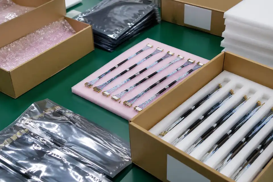
RF-tested micro-coax samples in protected packaging with non-readable batch and test labels
Shipment handoff scene with COC, test report files, and no fake impedance data
Micro-coaxial precision sample shipment preparation with trays, foam separators, and label context
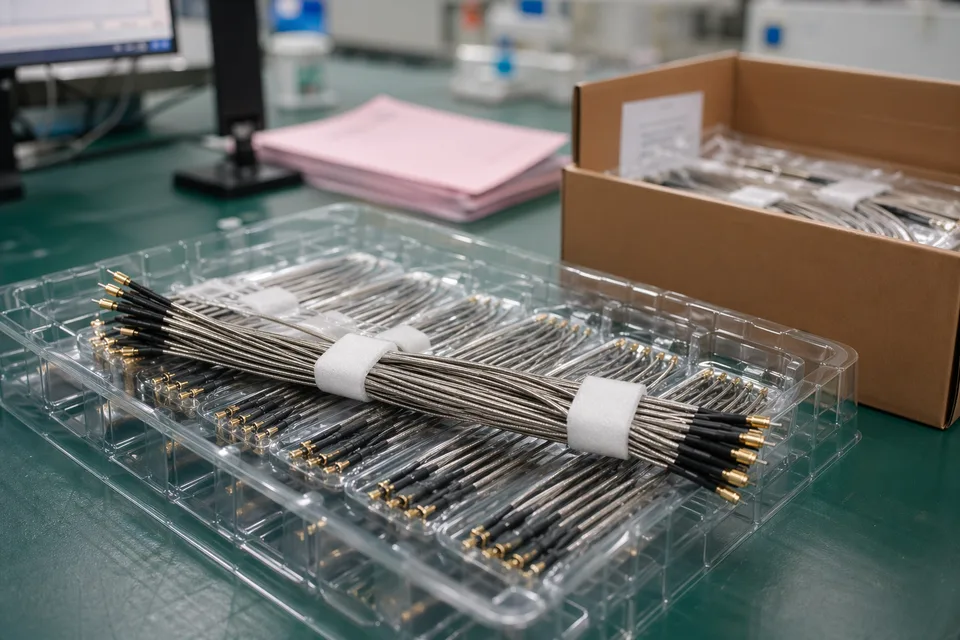
Micro-coaxial carton staging with protected fine connectors, traceability cards, and delivery support