Specification
REF-01Ribbon IDC Configurations
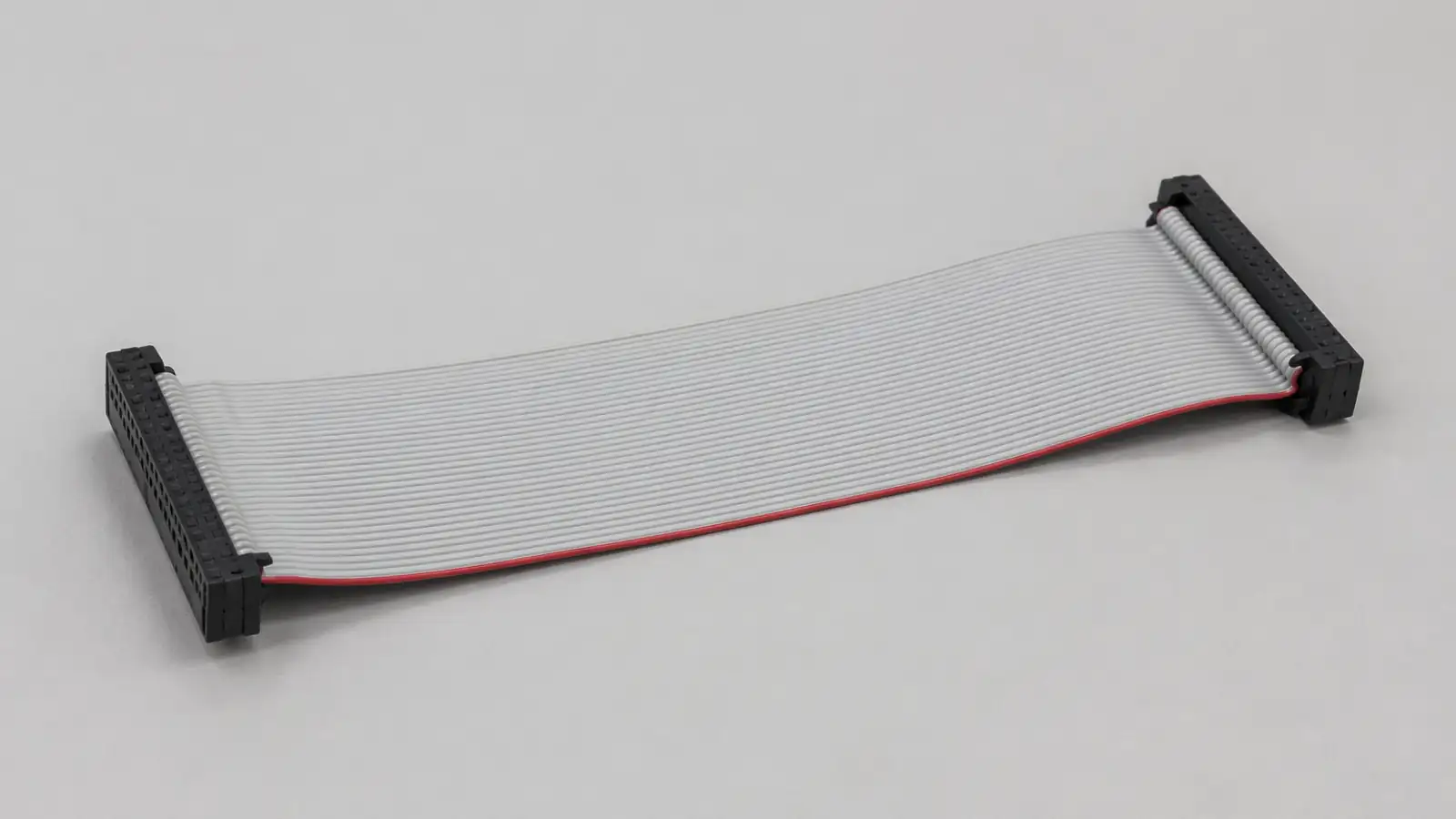
For standard ribbon and discrete IDC assembly formats that need cleaner structure definition.
IDCRibbonConfiguration
View Specification PageTechnical Reference · IDC-CABLE-ASSEMBLIES
Ribbon Interconnects
IDC Ribbon Solutions for Industrial Control, Internal Wiring, and OEM Flat-Cable Programs
EDPcable manufactures custom IDC ribbon cable assemblies for industrial control systems, telecom interconnect, equipment-internal wiring, and other flat-cable OEM programs. In IDC work, the first failure point is rarely pressing one sample together. It is usually whether pitch, connector format, pin mapping, and ribbon routing have all been thought through against the real installation, assembly, and service conditions. Once those conditions are sorted out early, drawing confirmation, sample review, and batch delivery usually involve far less back-and-forth. For projects that depend on stable pressing quality, clear pin definition, and repeatable batch execution, IDC is often one of the most direct ribbon-interconnect solutions to confirm.
Quick Links
QUICK ACCESSUse the project interface, structure, and application requirements to move into the right content.
Before moving into detailed specification review, most IDC programs need to confirm pitch, connector format, pin count, ribbon routing, assembly space, and verification scope. This stage is less about pushing samples forward and more about checking whether the IDC structure boundary is defined correctly.
| 01 | Pitch Options | 1.27mm, 2.0mm, 2.54mm, and other project-defined IDC pitch options |
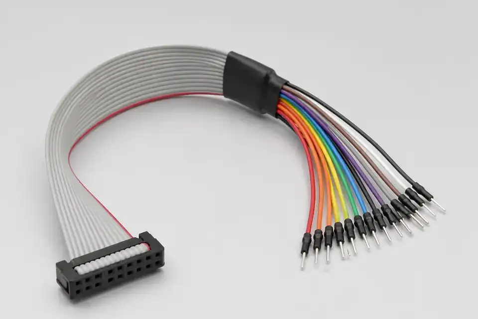
| 02 | Typical Structures | IDC ribbon cable, flat-cable assemblies, daisy-chain, and multi-way harness structures |
| 03 | Typical Applications | Industrial control systems, internal equipment wiring, telecom, and interface-extension projects |
| 04 | Pin Count Range | Project-defined pin-count and multi-way structure options |
| 05 | Shielding Direction | Standard and EMI-oriented ribbon structures based on application environment |
| 06 | Customization | Length, pitch, connector format, and assembly configuration |
| 07 | Production Support | Sample review, production setup, and OEM volume support |
| 08 | Verification | Continuity, visual inspection, and project-linked verification |
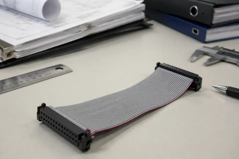
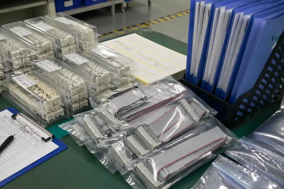
IDC ribbon finished assembly
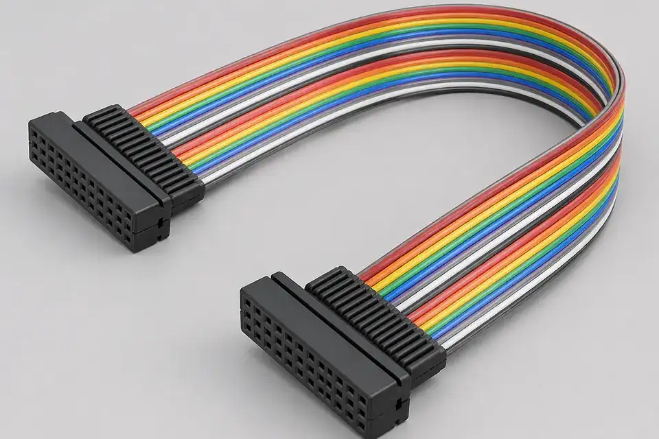
Pitch and connector-format detail
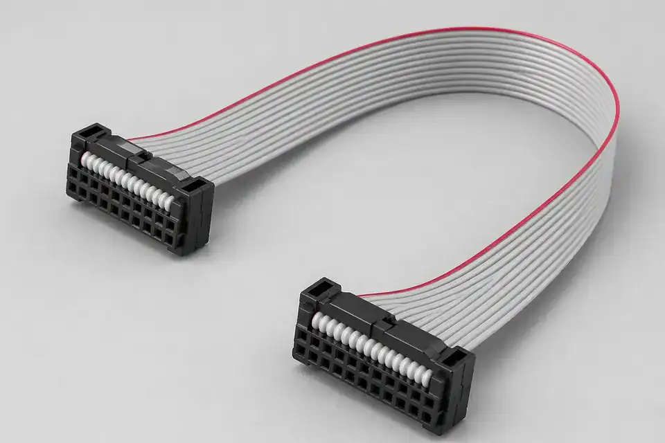
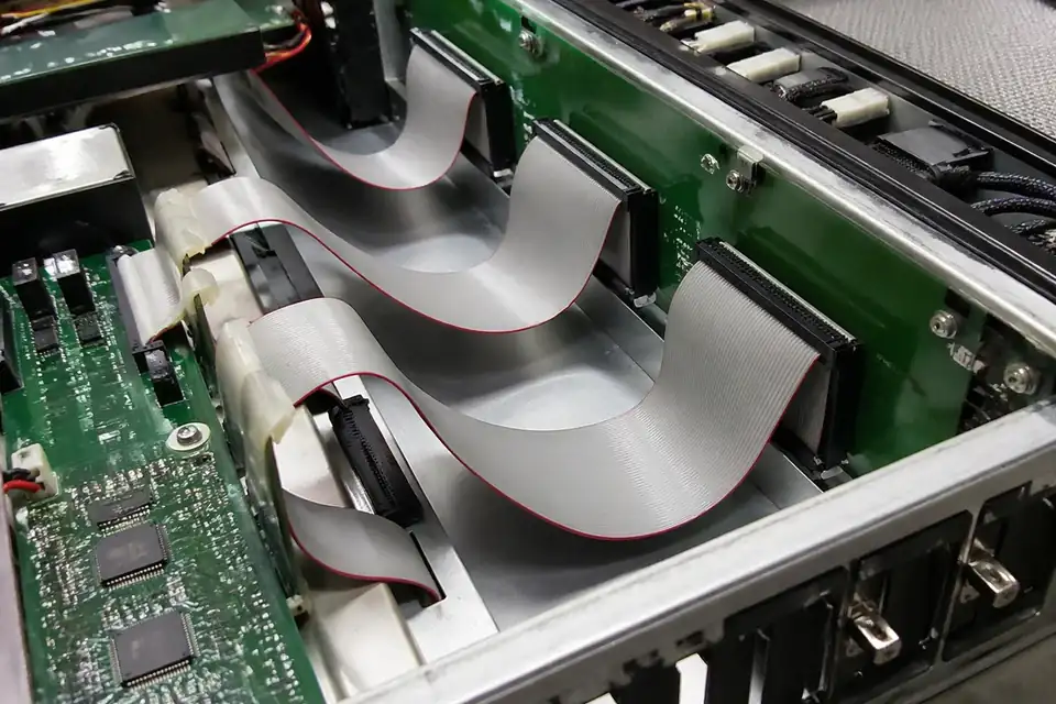
Multi-way harness structure
Organize connector, pin-count, pitch, routing-space, and release requirements before narrowing the manufacturing scope.
Specification
REF-01For standard ribbon and discrete IDC assembly formats that need cleaner structure definition.
Specification
REF-02For IDC RFQs that need 1.27mm, 2.0mm, or 2.54mm pitch selection tied to connector fit, cable format, and pin mapping.
Specification
REF-03For projects that need tighter control of pin mapping inside IDC harnesses.
Use device type, installed position, and validation focus to choose the matching application page.
Application
REF-01For cabinet, backplane, and industrial interconnect programs using IDC ribbon structures.
Application
REF-02For compact IDC-based interconnect systems in communications and interface-extension programs.
IDC engineering usually depends less on part complexity and more on whether pitch, connector format, pin order, pressing method, and ribbon routing are already settled. If those points are still in flux, samples, drawings, and process review tend to loop.
Confirm pitch, connector format, pin count, and whether the build is standard IDC, multi-way, or daisy-chain before sampling starts.
Review ribbon routing, bend space, flat-cable structure, and assembly conditions to ensure the design fits the actual installation environment.
Freeze connector format, pitch, pin mapping, length, and key process notes in a controlled drawing so the review basis, sample version, and released build stay tied to the same file set.
Move into controlled production only after the structure, drawing logic, and sample behavior are all confirmed.
IDC engineering drawing set
Ribbon routing or daisy-chain structure review
IDC programs usually carry tighter requirements around pressing consistency, pin stability, and ribbon-routing control. Rather than making broad quality claims, it is more convincing to show the actual pressing risks, verification items, and traceability records. Confidence comes from inspection logic, release records, and batch results that point back to the correct version.
Common risks in IDC work are not limited to continuity. They include pressing-depth variation, uneven force, unstable connector location, and batch-to-batch inconsistency.
Continuity and appearance are only the starting point. Pin consistency, routing execution, assembly fit, and project-linked verification also need to be confirmed clearly.
The relationship between sample definition, controlled drawings, inspection records, and batch release determines how well repeat orders and future issue tracing can be supported.
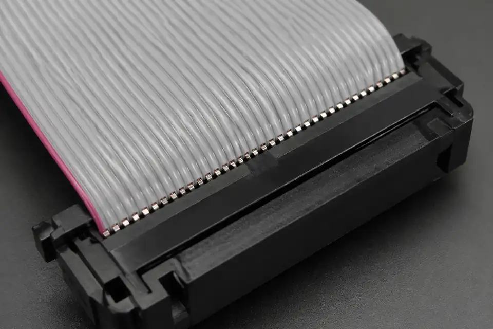
IDC pressing-quality detail
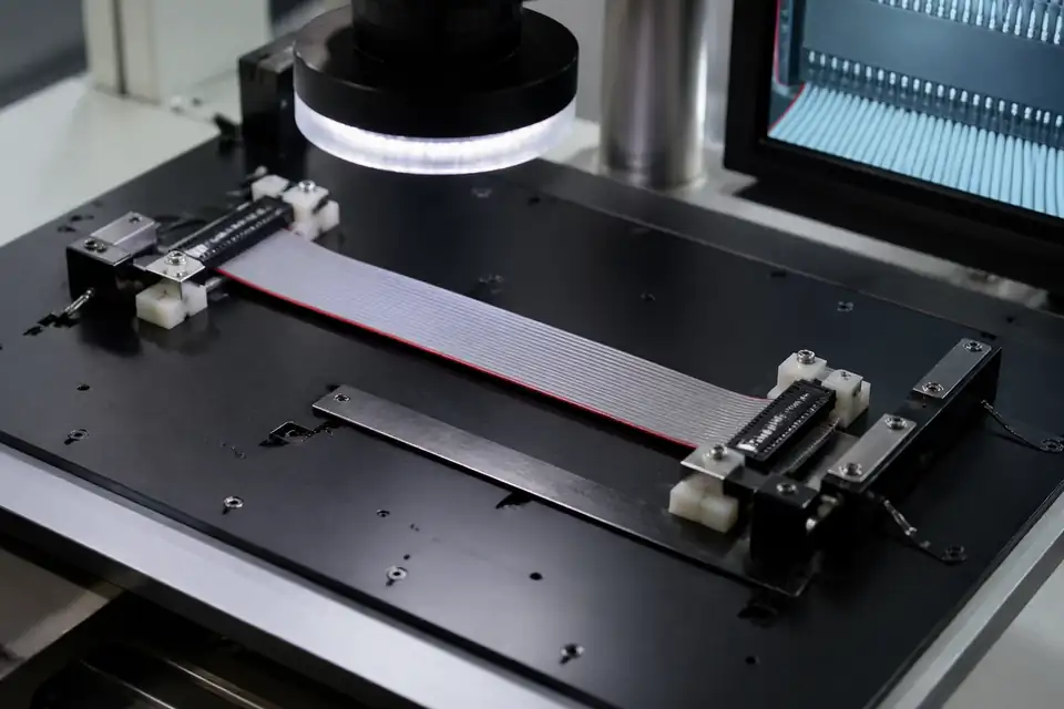
Pin-consistency inspection
Batch-release record
Industrial control wiring, telecom interconnect, and multi-way ribbon assemblies are three of the most common IDC project types. Each one places a different emphasis on engineering, quality, and delivery.
Most IDC programs move through scope definition, engineering review, sample validation, and controlled production. When the required inputs, review gates, and release points are defined early, sourcing and engineering teams can move faster internally.
Start from pitch, connector format, pin count, application context, and expected quantity so review begins from a clear scope.
Review routing, flat-cable structure, assembly approach, and manufacturability before the project moves into sample build or production.
Use drawing confirmation, sample build, and project-side evaluation to confirm that the structure is suitable for formal release.
Move into controlled production, final inspection, and shipment support under the approved definition, with the relevant records tied back to the released build.