Technical Reference · DATA-CENTER
Data Center Micro-Coax Applications
Custom Micro-Coax Cable Assemblies for Data Center Interconnects
For server and switch hardware whose released internal interface specifically calls for micro-coax
EDPcable supports custom micro-coax assemblies when the target data-center hardware already defines a micro-coax path. A server, BMC, switch, or patch label alone does not establish the cable type. The exact endpoint connectors, electrical interface, impedance target, length, routing density, shielding, service labels, test scope, and later batches must stay tied to one released drawing basis.
Quick Links
QUICK ACCESSStart with the sections closest to the project structure, interface requirements, and validation scope.
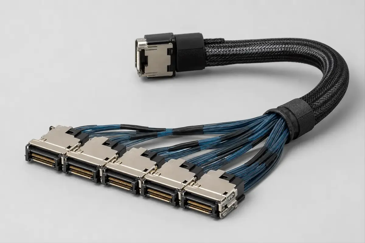
Data Center Micro-Coax Product Overview
Use this page only when the target hardware interface already specifies micro-coax and its endpoint connectors, pin map, electrical target, route, and test boundary can be confirmed before sampling.
| NO | Item | Typical Range or Meaning |
|---|---|---|
| 01 | Typical Equipment | Server or switch modules with a released internal micro-coax interface; the hardware category alone does not establish suitability |
| 02 | Common Structure | Project-defined short routes, multi-termination assemblies, dense routing, impedance targets, and shielding or grounding needs |
| 03 | Key Inputs | Full endpoint part numbers, pin map, length, routing density, impedance target, shielding and grounding, service labels, and batch requirement |
| 04 | Use Focus | Installation identification, repeatable assembly, and maintainable replacement |
| 05 | Quality Focus | Impedance consistency, shield integrity, batch variation, and clear shipment labels |
| 06 | Release Condition | Released interface, connector and pin map, length, impedance target, test scope, and batch tolerance must be clear enough for sampling |
Customer Pain Points
Data center micro-coax projects often sound straightforward once the product or route category is known. In real RFQ and sample work, delays usually appear in route fit, structure judgement, and revision control rather than in the label alone.
| NO | Customer Pain Point | Typical Risk | What Needs Early Confirmation |
|---|---|---|---|
| 01 | Product design issues | The connector path, structure, or local fit still does not truly match the data center micro-coax build, so the sample becomes only a temporary reference | Connector references, route path, structure boundaries, and installation space |
| 02 | Product quality issues | Execution, local fit, or batch consistency drifts across repeated data center micro-coax builds | Structure definition, quality focus, and revision linkage |
| 03 | Lead-time issues | Missing inputs force repeated sample loops and slow quotation, release, and batch timing | Connector data, route notes, project stage, quantity, and timing |
| 04 | After-sales issues | It becomes difficult to tell whether the issue came from structure, revision, or installed conditions | Drawing files, sample approval records, batch labels, and shipment records |
| 05 | Complaint-handling issues | Revision boundaries are unclear, so issue tracing stays slow | Revision confirmation, batch correspondence, and inspection records |
| 06 | Pricing issues | A broad request turns into repeated pricing changes once real fit constraints surface | Structure complexity, material expectations, quantity, and delivery boundaries |
Product Applications
This route is not only a category label. In practice, data center micro-coax work usually appears in device programs where fit, route logic, and revision scope all matter. The scenes below are the most common application contexts.
| NO | Application Scene | Scene Focus | Typical Concerns |
|---|---|---|---|
| 01 | AI server nodes | high-density internal high-speed signal routing | length tolerance, impedance consistency, and batch variation |
| 02 | Switch backplanes | compact multi-termination micro-coax paths | connector access, shielding, and repeatable assembly |
| 03 | BMC management routes | dense management interconnects with readable labels | terminal identification, maintenance, and traceability |
| 04 | Patch panel jumpers | short-length route organization and replaceability | length versions, label clarity, and shipment grouping |
| 05 | Hyperscale rack programs | multi-version production rhythm | batch stability, version switching, and release records |
Application Scene Visuals
IMAGES · 05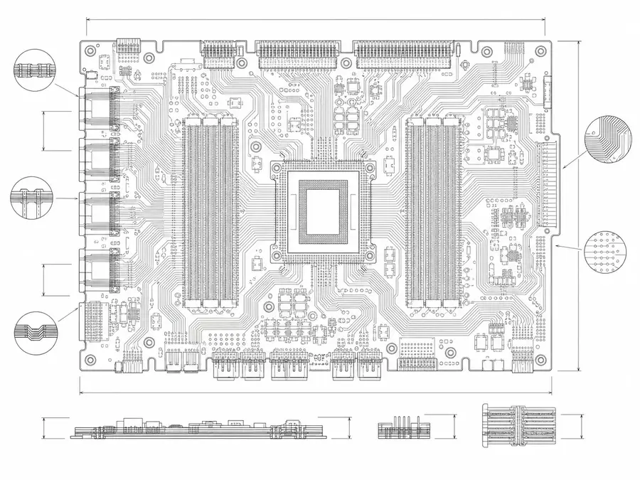
AI server node board line-art with high-density internal high-speed micro-coax routing, impedance consistency and length tolerance
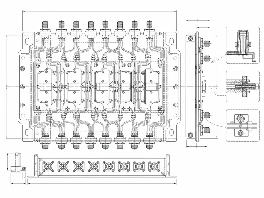
Switch backplane line-art with compact multi-termination micro-coax paths and connector access
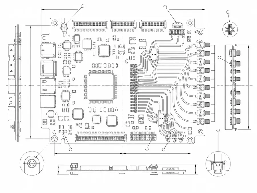
BMC management board line-art with dense management micro-coax interconnects and terminal identification points
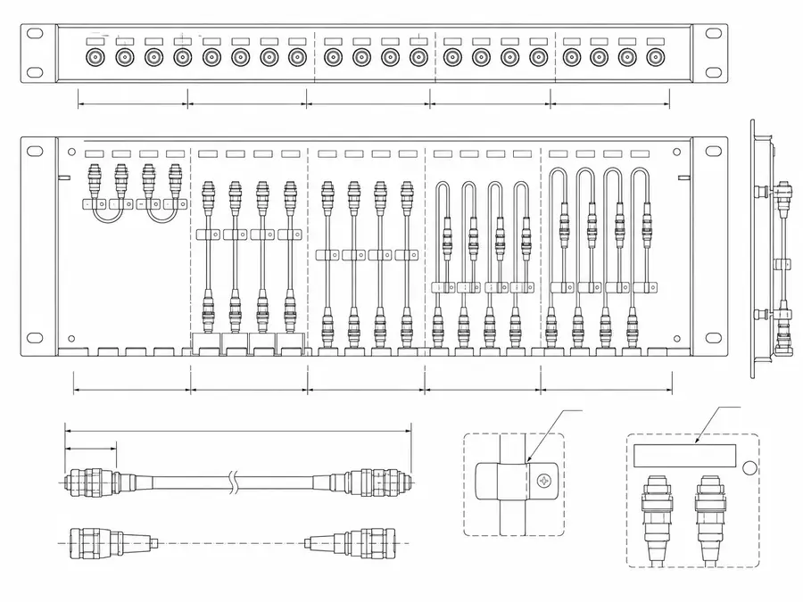
Patch-panel micro-coax jumpers line-art organized by short length with length-version grouping and label positions
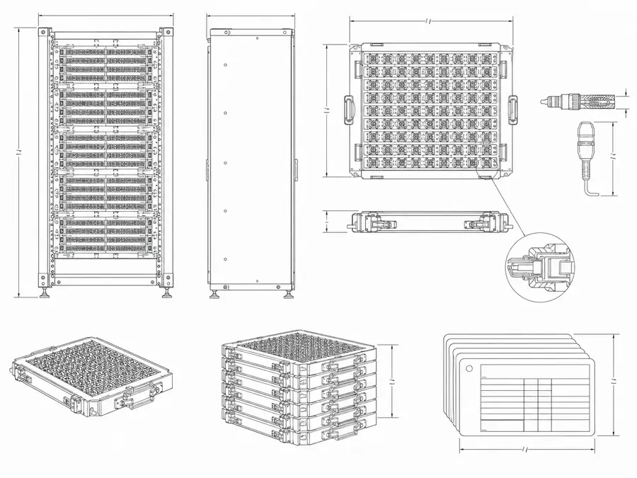
Hyperscale rack micro-coax program line-art with multi-version production trays and release-record cards
Data-Center Internal Micro-Coax Definition Matrix
A data-center label is too broad for a cable release. The RFQ must name the server, switch, accelerator, storage, or optical-module interface and define the complete internal channel.
| NO | Channel Field | Project Input | Release Boundary |
|---|---|---|---|
| 01 | Equipment context | Server, switch, storage, accelerator, or optical module | Named platform and revision |
| 02 | Protocol and generation | Exact electrical interface and operating mode | Source and sink requirements |
| 03 | Connector system | Complete board and cable-side part numbers | Manufacturer mating and cable range |
| 04 | Lane map | Differential pairs, grounds, sideband, and power contacts | Released pin and pair table |
| 05 | Channel length | Harness length plus board and connector transitions | End-to-end loss budget |
| 06 | Route environment | Airflow, heatsinks, service access, and neighboring power | Installed routing model |
| 07 | Grounding | Connector shells, grounds, chassis, and return distribution | Ground architecture |
| 08 | Qualification scope | Cable-level measurements and platform validation | Responsibility matrix |
First-Party Engineering References
- I-PEX CABLINE-UM connector data
Provides one high-density sourceable series with stated pitch, pins, cable options, current, and test context.
Data-Center Internal Channel Failure Modes
Dense equipment makes small connector, routing, and thermal changes visible at the channel level. The harness should not be described as protocol-capable until the named platform channel is validated.
| NO | Failure Mode | Channel Cause | Engineering Control |
|---|---|---|---|
| 01 | Link-training failure | Loss, reflection, or mapping exceeds platform margin | Validate exact source-to-sink channel |
| 02 | Lane intermittency | Connector preload changes during service or thermal movement | Control route support and mating |
| 03 | Crosstalk increase | Pair or ground allocation changes at dense transition | Lock pair grouping and return map |
| 04 | Thermal material drift | Harness runs beside heatsink or high-power module | Define actual temperature exposure |
| 05 | Airflow obstruction | Bundle or service loop blocks cooling path | Review cross-section and route volume |
| 06 | Wrong platform variant | Similar connector carries different lane mapping | Bind harness to equipment revision |
Data-Center Harness Verification Plan
The evidence chain moves from netlist and workmanship to channel measurement and finally the actual platform. A connector vendor's reference data does not close the server or switch validation.
| NO | Verification | Method | Acceptance Evidence |
|---|---|---|---|
| 01 | Pair and pin map | Continuity and shorts against released lane table | Per-assembly netlist result |
| 02 | Connector termination | Magnified joint and shield-transition inspection | First-article record |
| 03 | Installed route | Fit check around airflow and service features | Platform route approval |
| 04 | Impedance profile | Run differential TDR with the approved fixture, reference planes, rise time, and measurement window | Trace, impedance envelope, and numeric pass limits |
| 05 | Frequency response | Run the calibrated VNA or compliance fixture with the named port configuration and frequency range | Required S-parameters, measured data, and numeric pass limits |
| 06 | Platform operation | Link training and workload under customer conditions | System qualification record |
| 07 | Change control | Reassess connector, length, route, or material change | Approved revalidation decision |
Engineering Capability
Engineering value in a data center micro-coax page comes from tying route fit and structure judgement together before release. Cross-family engineering review, drawing control, and documentation practice are covered in the Related Capability Pages below.
Engineering Capability
Review route path, connector references, and local fit together for the data center micro-coax build.
Quality and Verification Highlights
Watch local-fit zones, connector exits, and route transitions specific to data center micro-coax installs.
Files and Batch Support
Data center micro-coax work has its own document layer around route and fitting boundaries. Cross-family file control, batch traceability, and certification practice are summarised in the Related Capability Pages.
Data center micro-coax route and fitting-boundary records
Capture the route path, local fit, and installation-space limits that are specific to the data center micro-coax build so later structural differences can be traced back to the right layer of change.
Certifications / Records Visuals
IMAGES · 04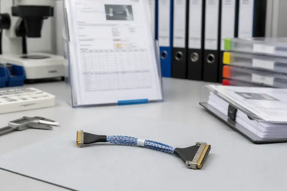
Micro-coaxial assembly document-control scene with records and labels secondary to the harness
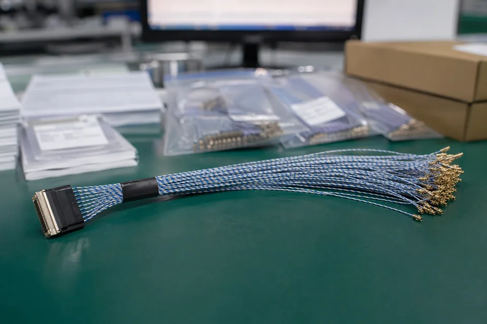
Micro-coaxial controlled record scene with compact harness sample foreground and document support
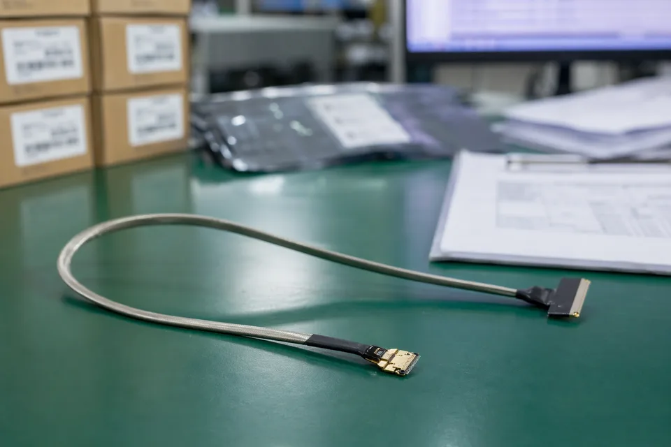
Micro-coaxial batch traceability archive with fine connector lot labels and cable sample visible
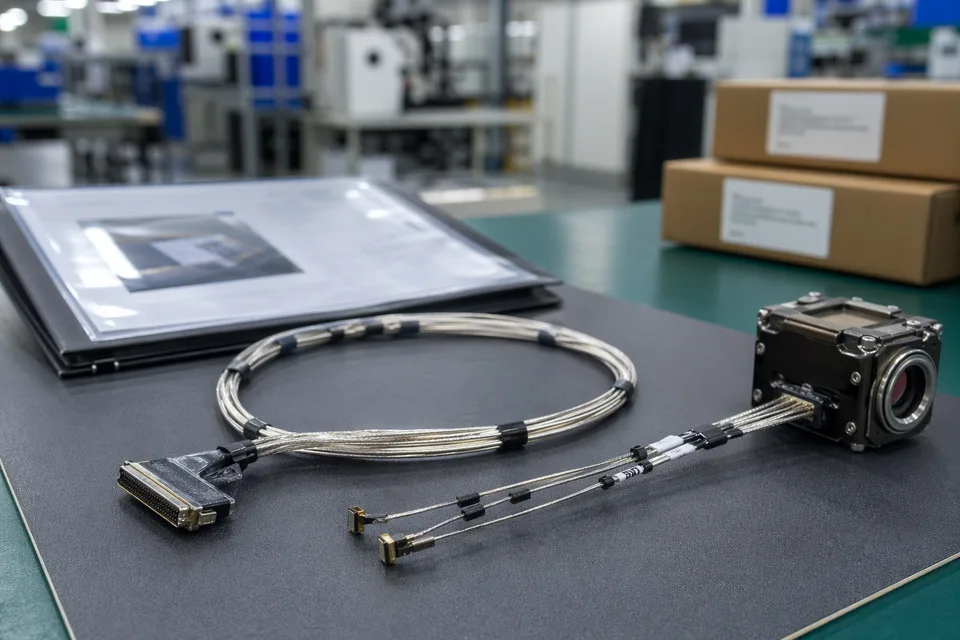
Micro-coaxial released-sample approval folder beside shielded harness and compact module mockup
FAQ
Can data center projects require batches to be exactly identical?
Reasonable tolerance ranges still apply. The allowed variation should be agreed during RFQ; out-of-range results trigger process review.
Can multiple termination combinations be quoted together?
Yes. Provide the termination list and quantity distribution early so quotation does not need repeated resets.
Is separate RF impedance testing always required?
It depends on the customer system requirement. If impedance is part of release, RF testing scope should be defined together with the cable assembly.
What MOQ applies to data center micro-coax programs?
There is no fixed public MOQ. It depends on the number of termination combinations, length versions, and impedance requirements.
Can an existing sample define the batch variation range?
Yes. Provide the sample, terminal definition, and historical acceptance data so the drawing and sampling strategy can be controlled.