Technical Reference · AR-VR
AR/VR Near-Eye Micro-Coax
Custom Micro-Coax Cable Assemblies for AR/VR and Smart Glasses
For HMD, smart-glasses, near-eye display, camera-module, and lightweight wearable signal routes
EDPcable supports custom micro-coax cable assemblies for AR/VR devices, HMDs, smart glasses, near-eye display modules, camera modules, sensor modules, and temple or hinge-zone routes. The challenge is not getting one sample built. It is making sure wire gauge, connector family, display signal path, shielding logic, first-bend behaviour, local enclosure space, and active prototype revision all stay aligned under one releasable definition.
Quick Links
QUICK ACCESSStart with the sections closest to the project structure, interface requirements, and validation scope.
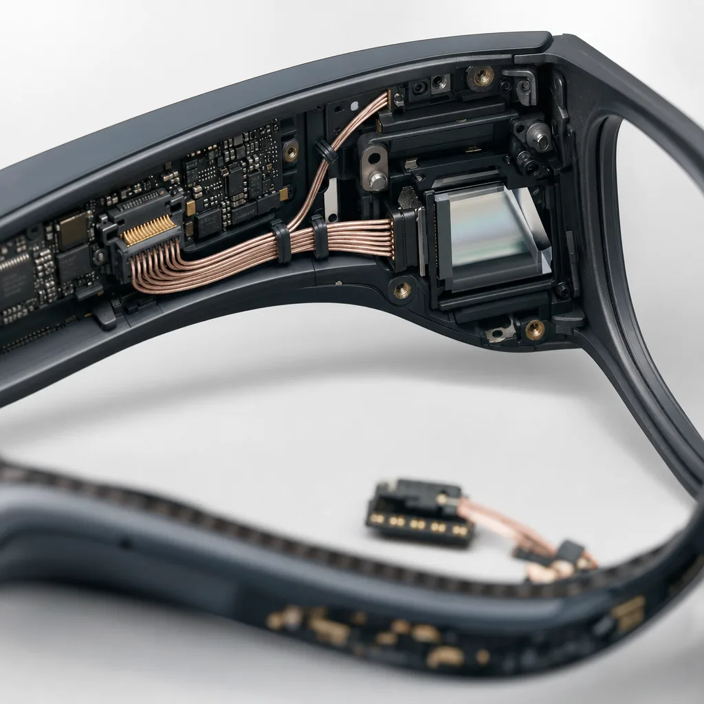
AR/VR Micro-Coax Product Overview
AR/VR micro-coax programs work best when the device context is already clear and the review can focus on the display path, camera or sensor route, hinge or temple space, shielding, weight, and revision boundary before sampling.
| NO | Item | Typical Range or Meaning |
|---|---|---|
| 01 | Typical Devices | HMDs, smart glasses, near-eye displays, AR optical modules, VR headsets, camera or sensor modules |
| 02 | Common Routes | Inside headset shells, temple arms, hinge zones, display-module-to-main-board links, camera-module-to-processor links |
| 03 | Key Inputs | Wire gauge, connector family, length, route path, shielding notes, bend zone, weight limit, revision scope |
| 04 | Engineering Focus | First-exit direction, temple or hinge fit, bend radius, fixing method, local stack height |
| 05 | Quality Focus | Stable termination, shielding repeatability, repeated assembly, sample-to-revision records |
| 06 | Recommended Links | 0.25mm pitch, I-PEX CABLINE-compatible, high-shielding, and laser-stripped capability pages |
Customer Pain Points
AR/VR micro-coax projects often sound straightforward once the product or route category is known. In real RFQ and sample work, delays usually appear in route fit, structure judgement, and revision control rather than in the label alone.
| NO | Customer Pain Point | Typical Risk | What Needs Early Confirmation |
|---|---|---|---|
| 01 | Product design issues | The connector path, structure, or local fit still does not truly match the AR/VR micro-coax build, so the sample becomes only a temporary reference | Connector references, route path, structure boundaries, and installation space |
| 02 | Product quality issues | Execution, local fit, or batch consistency drifts across repeated AR/VR micro-coax builds | Structure definition, quality focus, and revision linkage |
| 03 | Lead-time issues | Missing inputs force repeated sample loops and slow quotation, release, and batch timing | Connector data, route notes, project stage, quantity, and timing |
| 04 | After-sales issues | It becomes difficult to tell whether the issue came from structure, revision, or installed conditions | Drawing files, sample approval records, batch labels, and shipment records |
| 05 | Complaint-handling issues | Revision boundaries are unclear, so issue tracing stays slow | Revision confirmation, batch correspondence, and inspection records |
| 06 | Pricing issues | A broad request turns into repeated pricing changes once real fit constraints surface | Structure complexity, material expectations, quantity, and delivery boundaries |
Product Applications
This route is not only a category label. In practice, AR/VR micro-coax work usually appears in device programs where fit, route logic, and revision scope all matter. The scenes below are the most common application contexts.
| NO | Application Scene | Scene Focus | Typical Concerns |
|---|---|---|---|
| 01 | Near-eye display modules | high-density lightweight routing from display module to main board | first-exit space, connector fit, and revision pace |
| 02 | Smart-glasses temple routes | fine-gauge cable paths through thin arms or hinge-adjacent areas | bend behaviour, fixing method, and local stack height |
| 03 | VR headset internal links | multi-module interconnect with shielding and batch consistency | module layout changes, cable retention, and release boundaries |
| 04 | Camera and sensor modules | compact high-speed paths close to small imaging or sensing hardware | shielding, grounding, and local-space conflicts |
| 05 | Prototype-to-pilot programs | fast sample iteration that still needs traceable version control | sample IDs, route changes, and batch transition timing |
Application Scene Visuals
IMAGES · 05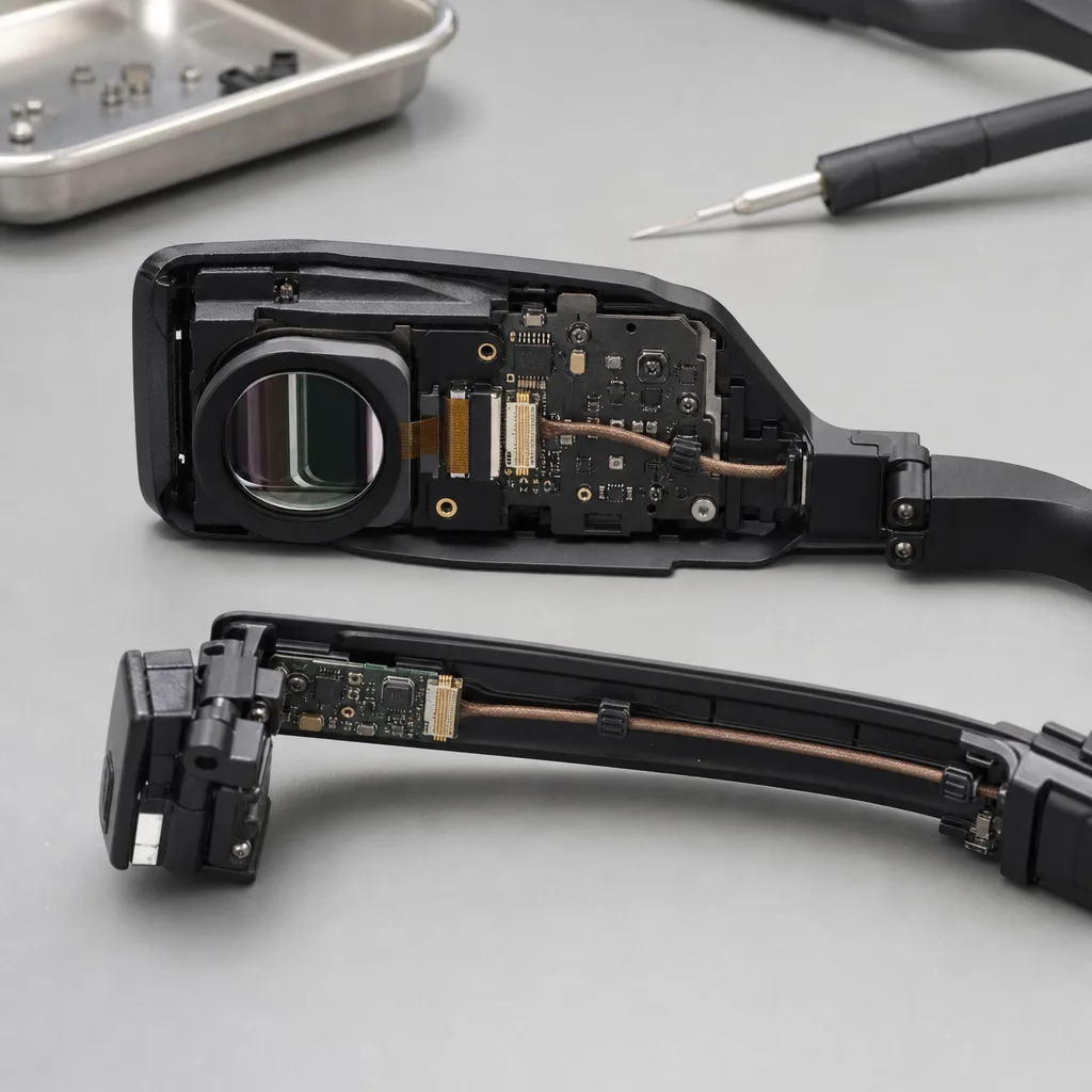
Non-branded near-eye AR display module line-art with a fine micro-coax cable routed from the display module to the main board, first-exit space and connector fit
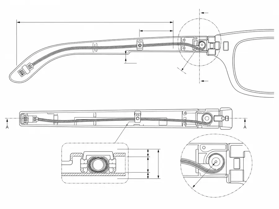
Smart-glasses temple and hinge line-art with a fine-gauge micro-coax cable path through the thin arm, bend behaviour and a retention clip
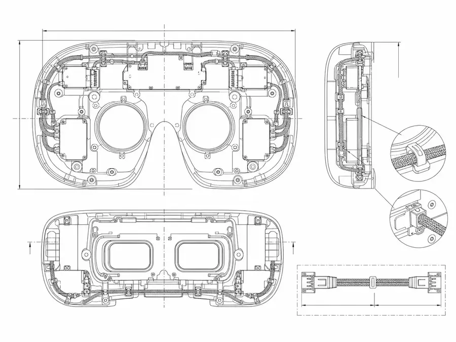
VR headset internal frame line-art with multiple modules linked by shielded micro-coax interconnects and cable retention
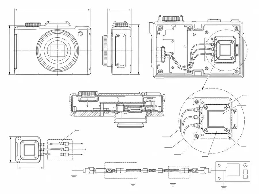
Compact camera and sensor module line-art with short high-speed micro-coax paths near small imaging hardware, shielding and grounding
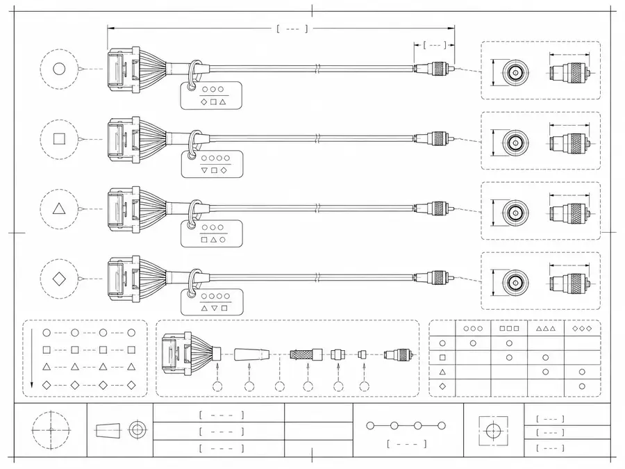
Prototype micro-coax harness set line-art with sample-id tags and version markers for fast iteration
AR/VR Wearable Interconnect Design Matrix
AR/VR micro-coax harnesses must fit the optical, display, camera, and sensor architecture within a lightweight enclosure and be evaluated under the defined user-motion profile. Temple and hinge geometry is reviewed with the electrical channel.
| NO | Design Variable | Required Definition | Release Artifact |
|---|---|---|---|
| 01 | Module endpoints | Display, camera, sensor, radio, or processor connection | Interface block diagram |
| 02 | Lane allocation | Coax, twinax, ground, control, and power mapping | Released pin table |
| 03 | Connector geometry | Pitch, positions, direction, height, and lock | Exact mating-pair drawings |
| 04 | Wearable route | Temple, hinge, bridge, headband, or display path | Enclosure route model |
| 05 | First bend | Distance and direction from each termination | Dimensioned exit detail |
| 06 | Motion profile | Angle, radius, cycle target, speed, and dwell | Customer-approved flex definition |
| 07 | Bundle construction | Wire sizes, shielding, reinforcement, and jacket | Controlled cross-section |
| 08 | Thermal and handling | Skin-side heat, assembly process, drops, and service | Device qualification inputs |
First-Party Engineering References
- I-PEX CABLINE-CA II connector data
Shows a sourceable 0.4 mm horizontal family; actual wearable channel limits remain configuration-specific.
AR/VR Harness Failure-Mode Review
Wearable failures often arise from geometry and assembly interaction: a sharp first bend, torsion in a hinge, or reinforcement that shifts the neutral axis. These are reviewed before setting any life claim.
| NO | Failure Mode | Mechanism | Control |
|---|---|---|---|
| 01 | Conductor fatigue | Repeated curvature concentrates outside designed flex zone | Define bend axis and neutral route |
| 02 | Shield fracture | Torsion and bending combine near a transition | Separate twist and bend where possible |
| 03 | Display artifact | Lane skew or intermittent joint changes under motion | Monitor channel during representative flex |
| 04 | Connector lift | Harness preload acts on low-profile mating pair | Relieve load before connector exit |
| 05 | Enclosure wear | Bundle rubs housing through repeated motion | Verify swept clearance and surface protection |
| 06 | Unsupported flex-life statement | Cycle count lacks radius, speed, load, and temperature | Publish complete test condition with result |
AR/VR Interconnect Verification Plan
A meaningful flex result names the specimen, installed geometry, monitored circuits, motion profile, environment, and failure rule. Connector catalog ratings do not replace harness motion testing.
| NO | Verification | Defined Condition | Evidence |
|---|---|---|---|
| 01 | Installed fit | Assembly placed in representative wearable enclosure | Clearance and preload review |
| 02 | Static electrical | Continuity, shorts, and project channel baseline | Pre-motion test record |
| 03 | Dynamic monitoring | Observe selected lanes during specified flex motion | Interruption and cycle log |
| 04 | Post-flex electrical | Repeat baseline after agreed cycle endpoint | Comparative result |
| 05 | Mechanical inspection | Inspect bend zone, shield, jacket, and exits | Magnified condition images |
| 06 | System display test | Customer validates released route in target device | Device behavior record |
| 07 | Revision control | Re-test geometry or material changes affecting flex | Approved qualification status |
Engineering Capability
Engineering value in an AR/VR micro-coax page comes from tying connector and wire-gauge selection to temple or hinge clearance, first-bend behaviour, weight, shielding, and the active prototype revision before release. Cross-family engineering review, drawing control, and documentation practice are covered in the Related Capability Pages below.
Engineering Capability
Review route path, connector references, and local fit together for the AR/VR micro-coax build.
Quality and Verification Highlights
Watch local-fit zones, connector exits, and route transitions specific to AR/VR micro-coax installs.
Evidence Chain
Route and prototype-version confirmation
Tie the device revision, display or sensor module position, harness route, and sample identifier together.
Connector-end and shielding inspection
Check connector ends, the first bend, shielding and grounding treatment, and local retention in the temple, hinge, or headset route.
Sample-to-pilot transition basis
Record sample approval, route changes, and the pilot-build revision boundary before prototype variants move into a small batch.
Files and Batch Support
AR/VR micro-coax work has its own document layer around route and fitting boundaries. Cross-family file control, batch traceability, and certification practice are summarised in the Related Capability Pages.
AR/VR micro-coax route and fitting-boundary records
Capture the route path, local fit, and installation-space limits that are specific to the AR/VR micro-coax build so later structural differences can be traced back to the right layer of change.
Certifications / Records Visuals
IMAGES · 04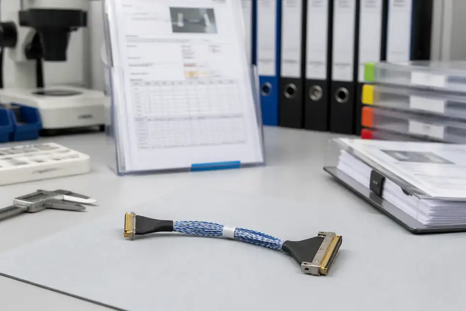
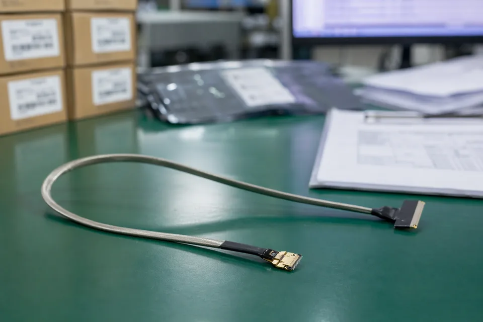
Micro-coaxial assembly document-control scene with records and labels secondary to the harness
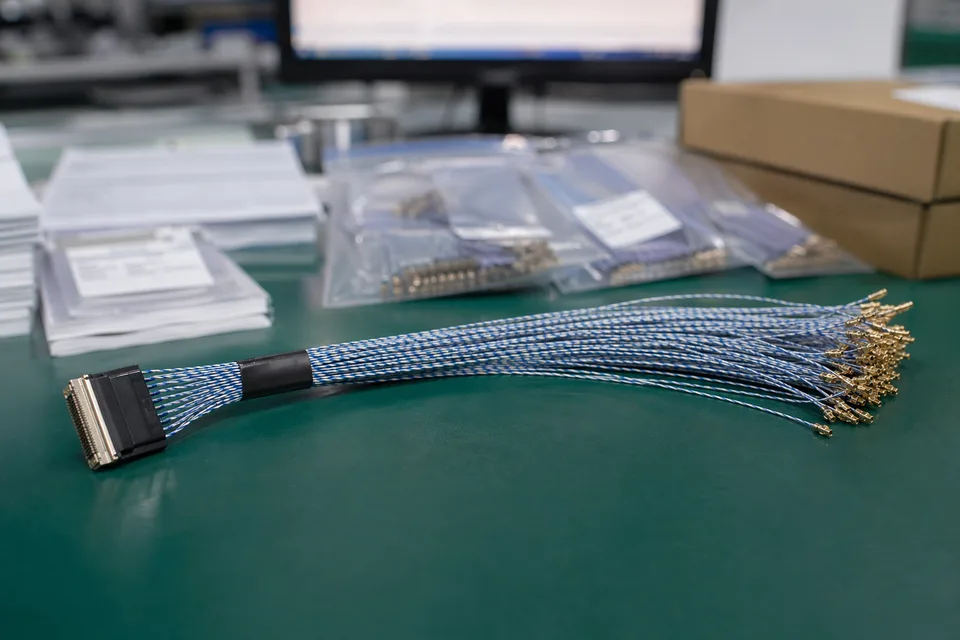
Micro-coaxial controlled record scene with compact harness sample foreground and document support
Micro-coaxial batch traceability archive with fine connector lot labels and cable sample visible
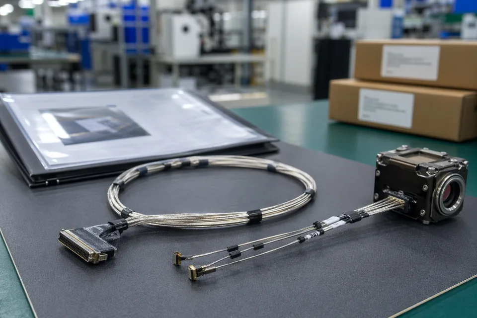
Micro-coaxial released-sample approval folder beside shielded harness and compact module mockup
FAQ
What information is needed for an AR/VR micro-coax quotation?
Send device type, module location, connector references, wire-gauge notes, length, route path, shielding context, prototype stage, and expected quantity.
How is this page different from the UAV page?
The AR/VR page focuses on HMDs, smart glasses, near-eye displays, and temple or headset routes. The UAV page focuses on drones, airborne cameras, gimbals, and motion-heavy aerial environments.
If the connector system is already I-PEX CABLINE, which page should I use?
Use the CABLINE connector page for mating and version boundaries, then use this AR/VR page to frame the device route and installation risk.
Can review start before full drawings are ready?
Yes. Early review can start from sample photos, module location, route sketch, connector references, and target length, then tighten when drawings are ready.
Can one cable assembly cover multiple AR/VR revisions?
Sometimes, but only if connector family, module location, route geometry, length, bend zone, and revision boundaries stay inside the same approved definition.