Technical Reference · SINGLE-USE-ENDOSCOPE
Disposable Endoscope Interconnect Programs
Cable Assemblies for Single-Use Endoscope Programs
Define the disposable cable boundary from camera module to handle and equipment interface
A single-use endoscope cable is a project-specific link between the imaging module, handle electronics and equipment interface. Begin by identifying which cable segment belongs to the disposable device and which interface stays with the reusable equipment. EDPcable can review a custom assembly against the OEM drawings, netlist, routing envelope and sample plan. The device manufacturer defines the intended use, material-contact boundary, processing method and final acceptance; a generic medical cable description cannot replace those inputs.
Quick Links
QUICK ACCESSStart with the sections closest to the project structure, interface requirements, and validation scope.
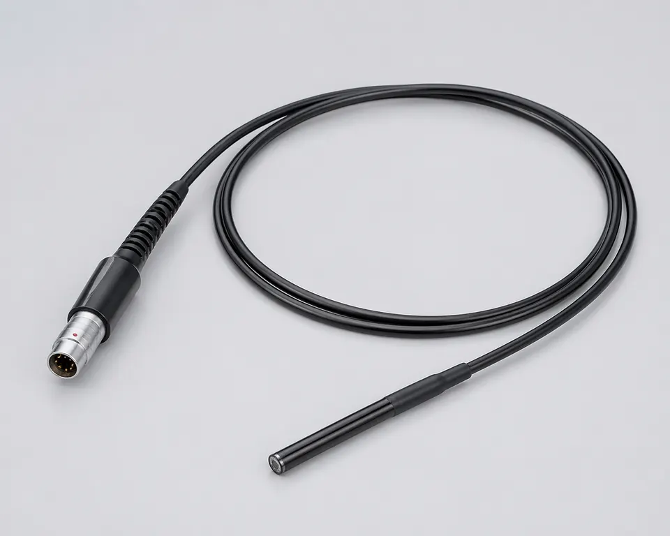
Locate the Disposable Assembly Boundary
Specify the distal-module connection, insertion-section route and handle-side breakout as separate zones of one drawing. The narrowest zone governs the bundle envelope, while the handle may need a different strain-relief or connector arrangement. If the disposable assembly mates to a reusable cable or processor, include that interface in the contact map without assuming both parts share the same service life or processing requirements.
| NO | Cable zone | Information needed for review |
|---|---|---|
| 01 | Camera end | Module interface, termination drawing and local connector space |
| 02 | Insertion section | Bundle diameter envelope, actual bend route and restraint locations |
| 03 | Handle breakout | PCB connector, conductor fan-out and load isolation |
| 04 | Reusable equipment interface | Mating identity and explicit disposable/reusable boundary |
| 05 | Delivery condition | Protection, cleanliness requirements and processing handoff |
| 06 | Validation boundary | Defined electrical checks and OEM device-image evaluation |
Resolve Endoscope Cable Ambiguities Before Sampling
An RFQ labelled disposable endoscope cable can refer to the distal camera lead, a handle harness or the complete equipment connection. Quoting them as the same item obscures the termination count and the interfaces that must be verified. Mark the requested assembly in a system diagram, with all supplied and customer-supplied components identified.
Use the camera module interface definition to establish the actual signal structure. Do not infer the data interface, lane count or impedance target from the word endoscope. If a module datasheet is confidential, supply a controlled interface extract that still identifies each net, electrical boundary and termination.
| NO | Ambiguity | Consequence | Clarification |
|---|---|---|---|
| 01 | Unspecified cable segment | Supplier and OEM count different endpoints | Highlight the exact supplied segment on a system diagram |
| 02 | Camera model omitted | Image interface remains undefined | Provide the released module interface or controlled extract |
| 03 | Disposable label used as a material specification | Processing compatibility is assumed without evidence | List materials, exposure conditions and required validation |
Single-Use Endoscope Cable Definition Matrix
The quote basis should identify both the camera path and the manufacturing handoff. Set physical dimensions from the insertion-section and handle drawings, then allocate nets and ground paths from the approved interface tables. Keep device processing and patient-contact requirements in their own defined acceptance scope so they are neither omitted nor silently claimed by a connector choice.
| NO | Definition item | Endoscope-specific decision | Required input |
|---|---|---|---|
| 01 | Disposable boundary | Choose distal-to-handle, handle-to-equipment or another explicit segment | System diagram identifying supplied endpoints and reusable parts |
| 02 | Camera interface | Assign imaging nets from the released module definition | Module option, interface table and connector contact view |
| 03 | Power and illumination | Separate module supply, returns and light-source conductors | Power allocation, loads and isolation requirements from the OEM |
| 04 | Insertion geometry | Fit the bundle within the actual shaft and moving zones | Diameter envelope, route drawing, length tolerances and restraints |
| 05 | Handle breakout | Protect the fan-out from assembly and connector loads | PCB interface, service access, exit direction and strain-relief drawing |
| 06 | Ground and shield | Define each return path and shield termination | Connection schedule across camera, handle and equipment boundary |
| 07 | Material and processing handoff | Identify allowed material build and supplied processing state | OEM material requirements, contact classification and exposure specification |
| 08 | Pack and identification | Keep device-variant identity visible without damaging fine terminations | Protection layout, label location, lot identifier and delivery quantity |
First-Party Engineering References
- I-PEX CABLINE-CA connector drawings and specifications
Example of manufacturer-controlled mating geometry and assembly documentation; actual connector selection is made from the customer endpoint drawings. This reference does not establish endoscope suitability or sterilization compatibility.
Endoscope Interconnect Failure-Mode Review
Image dropouts and visible artifacts should be investigated with a known module, harness revision and equipment configuration. Comparing uncontrolled camera options or routing the cable outside its intended restraints can obscure the source of a fault. These checks support the cable review; final imaging performance and device release stay within the OEM evaluation.
| NO | Observed issue | Cable-side question | Focused investigation |
|---|---|---|---|
| 01 | No camera image | Does the contact map match this module option? | Compare module and host net assignments before substitution |
| 02 | Intermittent image during steering | Is movement loading the distal joint or handle fan-out? | Observe the defined moving zone with approved restraints fitted |
| 03 | Noise after final assembly | Has the shield termination or return route changed? | Compare the installed ground schedule with the evaluated sample |
| 04 | Failed equipment connection | Are mating part number, key and contact view correct? | Check both actual endpoint drawings rather than external appearance |
| 05 | Damage after processing | Was the material build evaluated for the specified exposure? | Investigate the actual process with the device maker; do not assume compatibility |
| 06 | Mixed camera variants | Can the wrong harness enter the handle build? | Use variant-specific identification and verify the assembly pick list |
Verification and OEM Acceptance Handoff
Approve the verification sequence before ordering evaluation samples. Cable checks should identify the tested drawing and material build, with limits and fixture configuration recorded for any signal measurement. Use the OEM camera and processor arrangement for imaging evaluation. Where exposure or processing is relevant, the device manufacturer supplies the protocol and reviews the evidence instead of treating a standard continuity record as sufficient.
| NO | Check | Defined approach | Acceptance record |
|---|---|---|---|
| 01 | Endpoint identity | Compare camera, handle and equipment mates against approved parts | Signed endpoint and contact-view checklist |
| 02 | Netlist correspondence | Check continuity and shorts to the released mapping | Assembly test record tied to the endoscope variant |
| 03 | Distal termination | Inspect conductor preparation, local support and joint geometry | Magnified inspection and first-piece observations |
| 04 | Insertion-section fit | Install the cable in representative shaft and handle geometry | Fit approval noting restraints and moving-zone positions |
| 05 | Image-link behavior | Run the agreed camera configuration and required cable measurements | Report modes, fixtures, reference planes, results and agreed limits |
| 06 | Processing exposure | Evaluate the specified material build under the OEM protocol | Device-maker-reviewed exposure evidence and disposition |
| 07 | Delivery protection | Confirm packaging prevents handling load on small terminations | Approved packing arrangement and variant identification |
Engineering Review for the Camera-to-Handle Route
The insertion-section envelope and handle assembly sequence can impose different constraints on the same interconnect. Review the endpoint construction, assembly access and restraint scheme together before selecting a cable structure or accepting a replacement sample.
Engineering Capability
Use a contact-view netlist for both the distal and handle endpoints.
Specify support at the camera termination separately from handle-side strain relief.
Document module-option changes that alter the harness definition.
Verify the Harness Within Its Defined Device Route
Keep the camera module option visible on the evaluation record.
Inspect the transition into the insertion section before closing the handle.
Compare image behavior in the restrained route used for the device evaluation.
Evidence Chain
Camera-to-handle interface extract
Identify each signal and return with the module option, contact-view orientation and handle PCB endpoint.
Insertion-section installation record
Record the cable envelope, moving-zone support and handle exit used for the evaluated device sample.
Endoscope Program Documents
Define which endoscope-specific files accompany the cable delivery and which remain in the OEM device record. Certificate scope and device-level approvals must be checked separately.
Single-Use Endoscope Cable Questions
Is a single-use endoscope cable automatically suitable for sterilization?
No. State the intended supplied condition, material build and processing method. The device manufacturer determines the relevant protocol and reviews compatibility evidence for that defined build. Single-use describes the intended device-use model, not proof of material or processing suitability.
Should the camera lead and reusable equipment cable use the same specification?
Only where the actual interface requires it. Define their separate segments, mating boundary, handling conditions and acceptance scope; do not assume the disposable device and reusable equipment share one cable definition.
Can a cable sample replace the camera module pinout?
A sample helps with geometry and termination review, but it cannot establish reserved pins, signal direction, supplies or module-option differences. Confirm the sample against the approved module and host interface definitions.
What should be sent for the first quotation?
Send the marked system segment, both endpoint references, contact-view netlist, route and length drawing, camera option, material and processing handoff requirements, quantity and evaluation plan.