Technical Reference · MICRO-MEDICAL-HARNESS
Micro Medical Interconnects
Custom Micro Medical Wire Harness Assemblies
For miniature internal harnesses inside compact medical devices and sensor modules
EDPcable supports miniature internal wire harnesses for compact medical devices and sensor modules where connector size, point-to-point mapping, branch geometry, enclosure clearance, and handling during assembly define the build. Patient-contact lead sets and high-density ultrasound probe bundles follow their own application paths. Any dimensional, bend, pull, or electrical acceptance criterion must come from the connector drawing or the customer-approved validation plan.
Quick Links
QUICK ACCESSStart with the sections closest to the project structure, interface requirements, and validation scope.
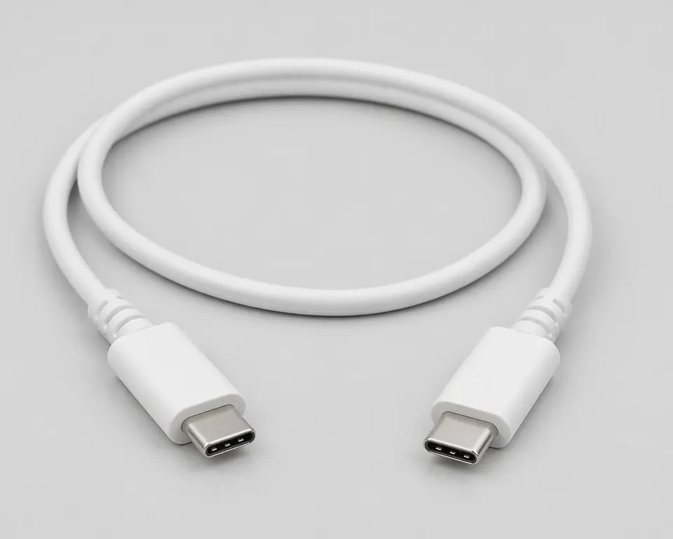
Micro Medical Harness Product Overview
Micro medical harness programs work best when the device context is already clear and the next review can focus on connector mapping, size boundaries, local fit, flexibility, and version scope before sampling.
| NO | Item | Typical Range or Meaning |
|---|---|---|
| 01 | Typical Devices | Compact medical devices, sensor modules, miniaturized internal harnesses |
| 02 | Common Structures | Fine wire harnesses, compact branch assemblies, small-device internal routes |
| 03 | Key Inputs | Connector references, pin mapping, size limits, flexibility notes, version scope |
| 04 | Use Focus | Local fit, repeated handling, compact routing, release clarity |
| 05 | Quality Focus | Batch stability, file correspondence, compact-structure execution |
| 06 | Release Basis | Connector data, route notes, size boundaries, and active version records |
Engineering Inputs
Use these items as first-round review inputs so the discussion does not rely on the page label alone.
Provide the device type and the main connector references or clear sample photos.
Include the active pin mapping, compact structure notes, and route boundaries.
Clarify flexibility expectations, local installation limits, and current device revision.
State whether the program is new development, replacement, validation, or batch transition.
Add expected sample quantity, batch quantity, and target timing.
Customer Pain Points
Micro medical harness projects often sound straightforward once the product or route category is known. In real RFQ and sample work, delays usually appear in route fit, structure judgement, and revision control rather than in the label alone.
| NO | Customer Pain Point | Typical Risk | What Needs Early Confirmation |
|---|---|---|---|
| 01 | Product design issues | The connector path, structure, or local fit still does not truly match the micro medical harness build, so the sample becomes only a temporary reference | Connector references, route path, structure boundaries, and installation space |
| 02 | Product quality issues | Execution, local fit, or batch consistency drifts across repeated micro medical harness builds | Structure definition, quality focus, and revision linkage |
| 03 | Lead-time issues | Missing inputs force repeated sample loops and slow quotation, release, and batch timing | Connector data, route notes, project stage, quantity, and timing |
| 04 | After-sales issues | It becomes difficult to tell whether the issue came from structure, revision, or installed conditions | Drawing files, sample approval records, batch labels, and shipment records |
| 05 | Complaint-handling issues | Revision boundaries are unclear, so issue tracing stays slow | Revision confirmation, batch correspondence, and inspection records |
| 06 | Pricing issues | A broad request turns into repeated pricing changes once real fit constraints surface | Structure complexity, material expectations, quantity, and delivery boundaries |
Product Applications
Miniature medical harnesses in this scope are internal device assemblies. Connector drawings, mapping, branch geometry, enclosure clearance, and assembly handling define the release boundary.
| NO | Application Scene | Scene Focus | Typical Concerns |
|---|---|---|---|
| 01 | Compact diagnostic modules | finer structure and local-fit control inside smaller housings | connector matching, size limits, and route path |
| 02 | Sensor assemblies | stable branch definition with cleaner small-scale execution | pin mapping, flexibility, and local protection |
| 03 | Miniature internal sensor links | short routes between compact device modules | connector exits, branch protection, and enclosure clearance |
| 04 | Portable medical terminals | small-device routing with controlled released scope | version records, batch consistency, and after-sales tracing |
| 05 | Replacement and upgrade programs | matching old compact harnesses to the active platform | usable scope, sample confirmation, and issue tracing |
Application Scene Visuals
IMAGES · 05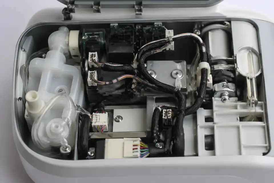
Micro medical harness inside a compact portable medical device
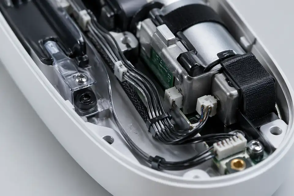
Micro medical harness inside a compact handheld medical device
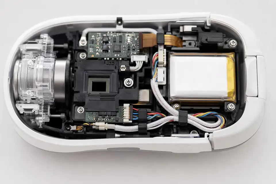
Micro medical harness inside a miniature diagnostic handheld unit
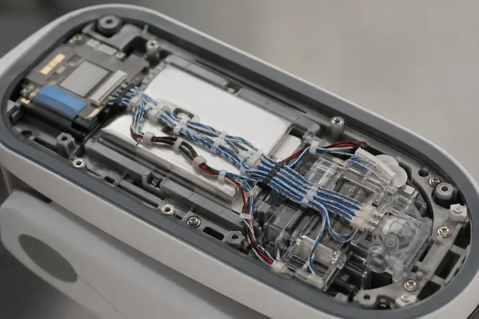
Micro medical harness inside a portable sensor-driven medical device
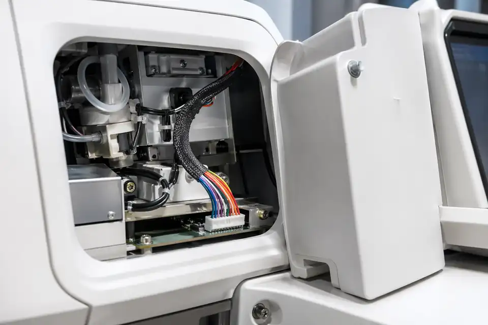
Micro medical harness inside a small medical terminal module
Micro Medical Harness Design Definition Matrix
A miniature internal harness is released from exact connector, wire, mapping, enclosure, and inspection inputs. Fine geometry does not create a universal bend, retention, or electrical rating for the assembled harness.
| NO | Miniature design input | Definition to freeze | Release evidence |
|---|---|---|---|
| 01 | Mating connector identity | Capture full manufacturer series, exact housing and contact part numbers, keying, orientation, mate, and allowable contact population. | Approved BOM and current component drawings matched to the compact device interface. |
| 02 | Fine-wire construction | Specify conductor material, gauge, strand construction, insulation, color, twist or grouping, and any customer-required material declaration. | Wire specification and purchase identity controlled at the active harness revision. |
| 03 | Point-to-point map | Define every cavity assignment, splice, branch endpoint, shield or drain path, and intentionally unused position without relying on sample color alone. | Connection schedule approved alongside the miniature connector orientation view. |
| 04 | Enclosure envelope and exit direction | Set maximum local bundle size, breakout position, connector exit, keep-out zones, free length, and assembly access from the actual housing geometry. | Dimensioned route drawing or customer model with inspection datums. |
| 05 | Installation bend and handling | Separate one-time placement bends from repeated service motion, and define local support where technicians push or route the fine wires. | Installation work instruction plus any customer-authored motion requirement. |
| 06 | Termination process boundary | Use contact-maker requirements and the released process definition for strip length, conductor preparation, tooling, and inspection without inventing generic limits. | Termination specification tied to terminal, wire, tooling, and applicable workmanship class. |
| 07 | Inspection access and sampling | Agree which features require magnification, dimensional measurement, mechanical sampling, or electrical test and how inaccessible joints are qualified. | Inspection plan naming sample stage, method, acceptance source, and retained record. |
First-Party Engineering References
- ISO 13485:2016 quality management systems for medical devices
This quality-system reference informs document, supplier, process, and traceability expectations when contractually applicable; it is not a product approval for the miniature harness.
- IPC/WHMA-A-620E cable and wire harness acceptance overview
The customer may invoke workmanship and assembly acceptance criteria from IPC/WHMA-A-620E, while drawing-specific geometry and inspection frequency still require project definition.
Micro Medical Harness Failure-Mode Review
Miniature construction concentrates risk at connector orientation, prepared conductors, tight route transitions, and inspection access. Controls below address assembly conformity rather than the medical device's complete safety case.
| NO | Potential micro-harness failure | Focused assembly control | Boundary requiring customer input |
|---|---|---|---|
| 01 | Correct connector family is installed in the wrong orientation | Use keyed visual masters, cavity-one identification, fixture orientation, and independent mapping confirmation before the first article is accepted. | The device team confirms mechanical mating and function inside the target enclosure. |
| 02 | Fine strands or insulation are damaged during preparation | Set preparation and inspection criteria for the exact wire-contact combination, including magnification when the released plan requires it. | Allowable damage and any sectioning evidence come from the invoked component or customer specification. |
| 03 | Compact branch geometry creates hidden tension after installation | Review free length, breakout position, bend transition, and local restraint in the real assembly sequence before freezing dimensions. | The equipment owner supplies enclosure tolerance, installation force, and service-access assumptions. |
| 04 | Terminal or solder joint is stressed by handling close to the housing | Define conductor support and technician handling points, then perform only the project-specified mechanical sample check on representative builds. | No flex-life or pull capability is generalized beyond the agreed fixture and acceptance criteria. |
| 05 | Unreviewed wire or contact substitution changes fit or termination behavior | Lock approved manufacturer part numbers and route any alternate through drawing, process, sample, and verification review before use. | Device-impact assessment and regulatory file updates remain the customer's responsibility. |
Micro Medical Harness Verification Plan
Verification combines complete mapping checks with focused dimensional and workmanship evidence selected for the tiny interfaces. Any performance limit is taken from the exact BOM or customer-approved specification.
| NO | Verification target | Project-defined execution | Evidence retained |
|---|---|---|---|
| 01 | Cavity assignment and circuit identity | Test the complete connection schedule using named connector positions and verify required opens or splices instead of relying on wire colors. | Continuity report linked to the point-to-point map and serialized sample set. |
| 02 | Miniature envelope and branch dimensions | Measure connector exits, branch locations, local bundle diameter, free lengths, and defined keep-out clearances from the released datums. | Dimensional report with measurement method and drawing revision. |
| 03 | Prepared wire and termination appearance | Inspect the specified conductor, insulation, contact seating, soldered feature, and contamination criteria at the agreed magnification and sample stage. | Photographic or checklist evidence identified to terminal and wire combination. |
| 04 | Contact retention or joint strength | Apply the exact component instruction or customer plan for sample quantity, pull direction, rate, limit, and post-test disposition. | Mechanical sample result that does not extrapolate beyond the tested construction. |
| 05 | BOM and material identity | Reconcile connector, contact, wire, insulation, labels, and approved alternates with purchase and build records before lot closure. | Lot traceability index and documented deviation status where applicable. |
| 06 | Installed first-article fit | Evaluate routing, mating access, conductor support, and enclosure interference in a customer fixture or device representative of the released geometry. | Fit-review approval naming the hardware, model, and harness revisions used. |
Engineering Capability
Miniature internal-harness review ties connector drawings, point-to-point mapping, branch geometry, wire exit, enclosure clearance, and assembly sequence to one released definition.
Engineering Capability
Review route path, connector references, and local fit together for the micro medical harness build.
Quality and Verification Highlights
Watch local-fit zones, connector exits, and route transitions specific to micro medical harness installs.
Evidence Chain
Controlled miniature-harness drawing
Tie connector references, point-to-point mapping, branch dimensions, wire exits, enclosure limits, and the active revision to one released drawing.
Enclosure-fit and handling review
Record connector fit, fixing points, local clearance, and customer-defined handling checks for the approved compact-device installation.
Approved sample and batch correspondence
Keep sample approval, project-defined inspection results, batch labels, and shipment records linked to the same miniature-harness revision.
Files and Batch Support
Micro medical harness work has its own document layer around route and fitting boundaries. Cross-family file control, batch traceability, and certification practice are summarised in the Related Capability Pages.
Micro medical harness route and fitting-boundary records
Capture the route path, local fit, and installation-space limits that are specific to the micro medical harness build so later structural differences can be traced back to the right layer of change.
Certifications / Records Visuals
IMAGES · 04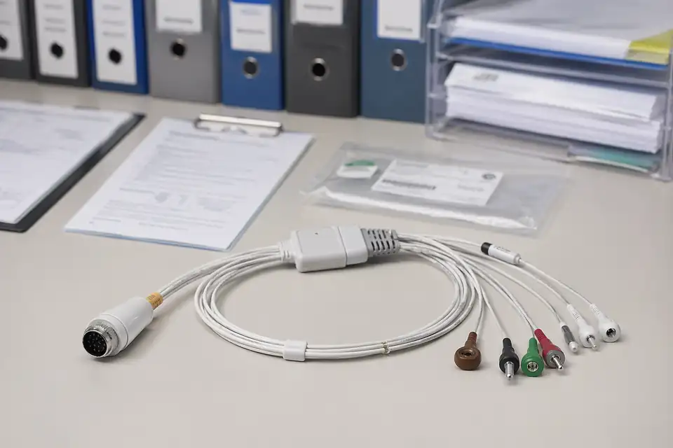
Medical cable assembly compliance and batch-record scene with documents secondary to the harness
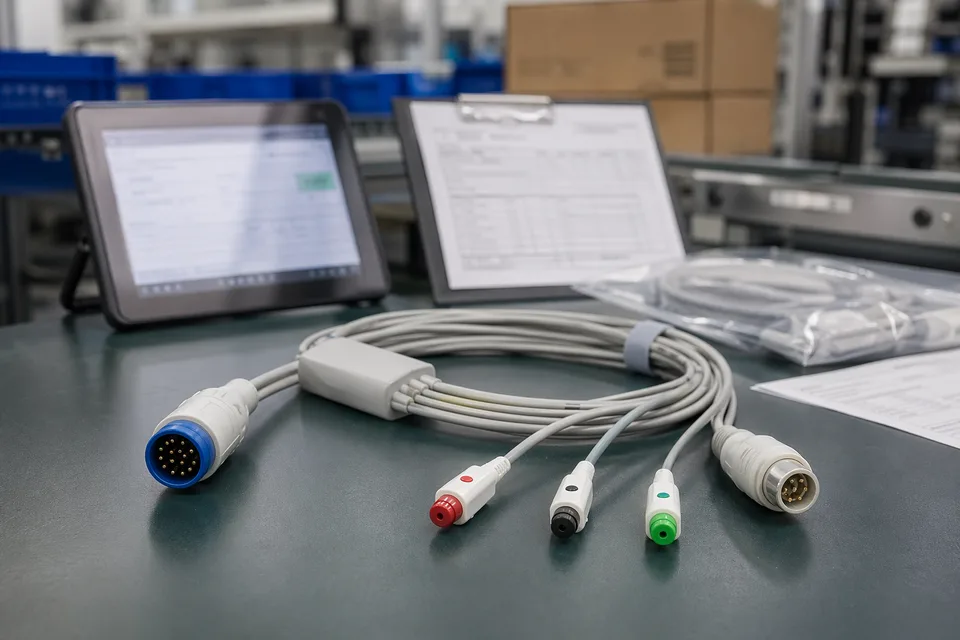
Medical cable compliance record scene with harness sample foreground and controlled documents
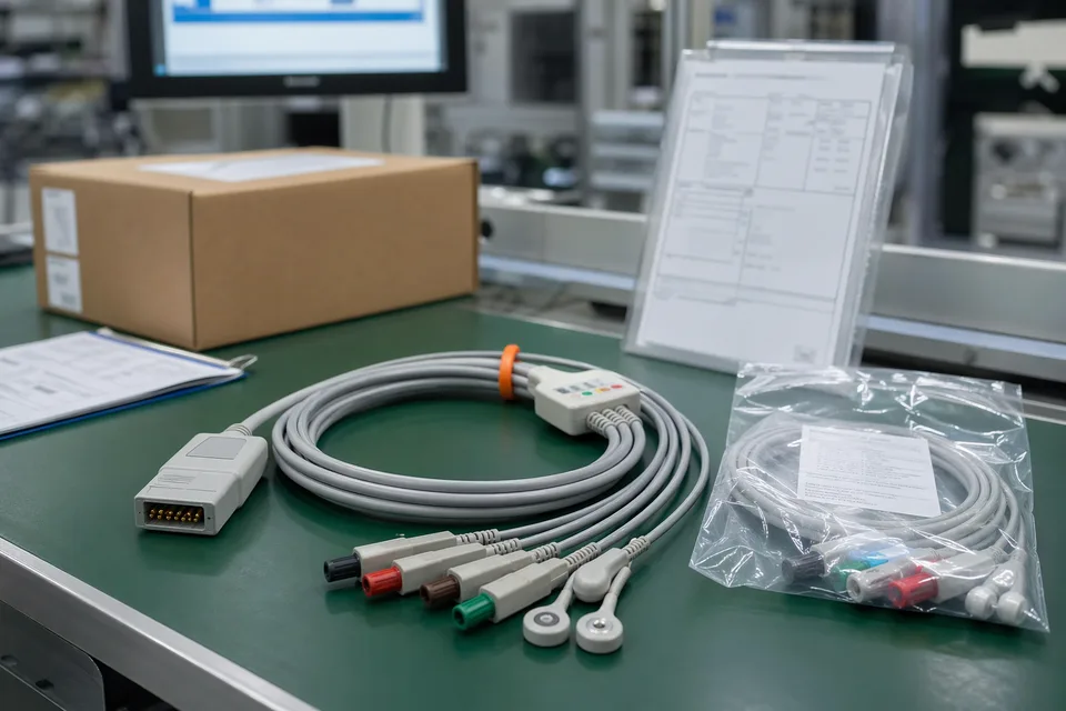
Medical cable batch traceability and sample approval archive in clean workspace
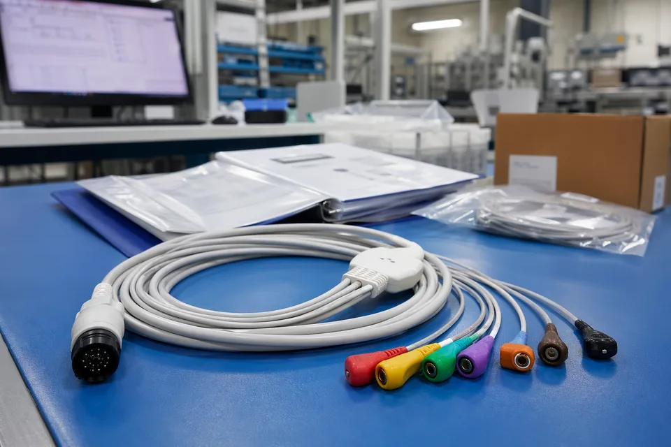
Medical released project folder with connector lot labels and sample cable support context
FAQ
Can you build micro medical harnesses from old samples or old parts?
Yes. Existing samples help, but connector mapping, size limits, flexibility notes, and active device revision still need to be confirmed before the sample can represent the released build.
What is the minimum input for a micro medical harness quotation?
Send the device type, connector references, pin mapping, size limits, project stage, and expected quantity.
Why do micro medical harness programs need more than connector model and cable length?
Because local fit, structure boundaries, branch logic, and version scope often decide whether the harness can actually be released cleanly.
Can one micro medical harness cover several device versions?
Sometimes, but only if mapping definition, size limits, structure geometry, and revision boundaries stay inside the same approved definition.
Can review start before the full drawing package is complete?
Yes. Early review can start from connector references, compact-route context, and current structure limits, then tighten as the file package becomes clearer.