Technical Reference · DIAGNOSTIC-EQUIPMENT
Diagnostic Equipment Interconnects
Custom Cable Assemblies for Diagnostic Equipment
For internal harnesses in diagnostic analyzers, testing systems, and equipment modules
EDPcable supports internal cable assemblies for diagnostic analyzers, testing systems, carts, and equipment modules. Confirm the module interface map, power and signal grouping, connector drawings, shielding and grounding inputs, route and service limits, labels, and customer validation checkpoints. Patient-contact lead sets and ultrasound probe bundles follow their own device-specific directions.
Quick Links
QUICK ACCESSStart with the sections closest to the project structure, interface requirements, and validation scope.
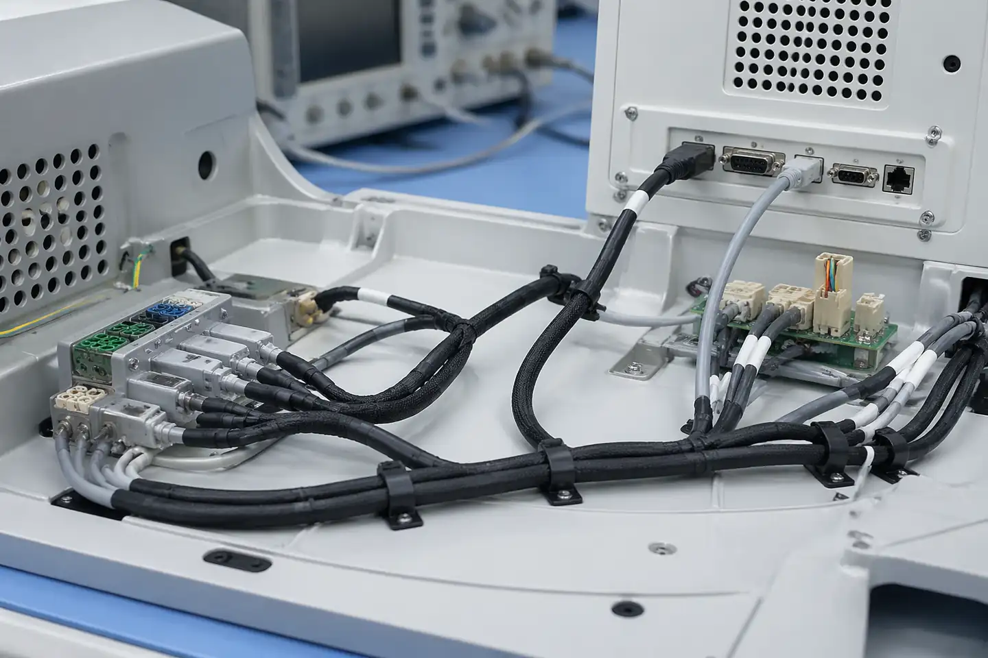
Diagnostic Equipment Cable Product Overview
Diagnostic-equipment cable programs work best when the device context is already clear and the next review can focus on connector mapping, structure limits, validation expectations, and released version scope before sampling.
| NO | Item | Typical Range or Meaning |
|---|---|---|
| 01 | Typical Devices | Diagnostic systems, testing devices, analysis modules, lab-use medical equipment |
| 02 | Common Structures | Multi-core harnesses, branched assemblies, internal equipment routes, traceable subassemblies |
| 03 | Key Inputs | Connector mapping, structure boundaries, validation notes, revision scope |
| 04 | Use Focus | Assembly stability, validation rhythm, released file correspondence, device-side fit |
| 05 | Quality Focus | Batch consistency, review records, traceable delivery, long-run support |
| 06 | Release Basis | Connector data, structure definition, validation notes, and active version records |
Customer Pain Points
Diagnostic-equipment cable projects often sound straightforward once the product or route category is known. In real RFQ and sample work, delays usually appear in route fit, structure judgement, and revision control rather than in the label alone.
| NO | Customer Pain Point | Typical Risk | What Needs Early Confirmation |
|---|---|---|---|
| 01 | Product design issues | The connector path, structure, or local fit still does not truly match the diagnostic-equipment cable build, so the sample becomes only a temporary reference | Connector references, route path, structure boundaries, and installation space |
| 02 | Product quality issues | Execution, local fit, or batch consistency drifts across repeated diagnostic-equipment cable builds | Structure definition, quality focus, and revision linkage |
| 03 | Lead-time issues | Missing inputs force repeated sample loops and slow quotation, release, and batch timing | Connector data, route notes, project stage, quantity, and timing |
| 04 | After-sales issues | It becomes difficult to tell whether the issue came from structure, revision, or installed conditions | Drawing files, sample approval records, batch labels, and shipment records |
| 05 | Complaint-handling issues | Revision boundaries are unclear, so issue tracing stays slow | Revision confirmation, batch correspondence, and inspection records |
| 06 | Pricing issues | A broad request turns into repeated pricing changes once real fit constraints surface | Structure complexity, material expectations, quantity, and delivery boundaries |
Product Applications
Diagnostic-equipment harnesses in this scope connect internal modules and equipment-side interfaces. Module boundaries, mapping, shielding and grounding inputs, service access, and validation checkpoints define the release.
| NO | Application Scene | Scene Focus | Typical Concerns |
|---|---|---|---|
| 01 | Laboratory testing systems | structure stability and validation-ready file control | connector mapping, release notes, and sample boundaries |
| 02 | Analysis modules | compact internal execution with clearer version correspondence | local fit, branch logic, and structure discipline |
| 03 | Diagnostic carts and stations | repeatable delivery and issue tracing across staged builds | batch labels, shipment records, and approval output |
| 04 | Validation-heavy pilot programs | sample-to-release continuity before batch introduction | review timing, document control, and released basis |
| 05 | Replacement and upgrade programs | matching old diagnostic harnesses to the active platform | usable scope, after-sales support, and traceable differences |
Application Scene Visuals
IMAGES · 05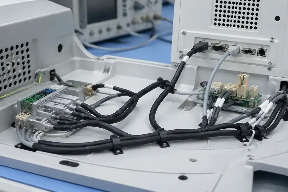
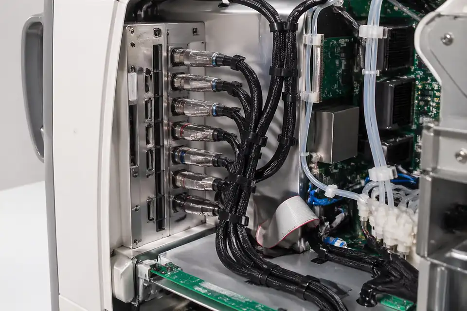
Diagnostic-equipment cable assembly inside a diagnostic system main unit
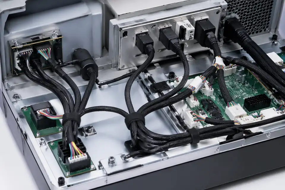
Diagnostic-equipment cable assembly inside a larger diagnostic system with multiple interfaces
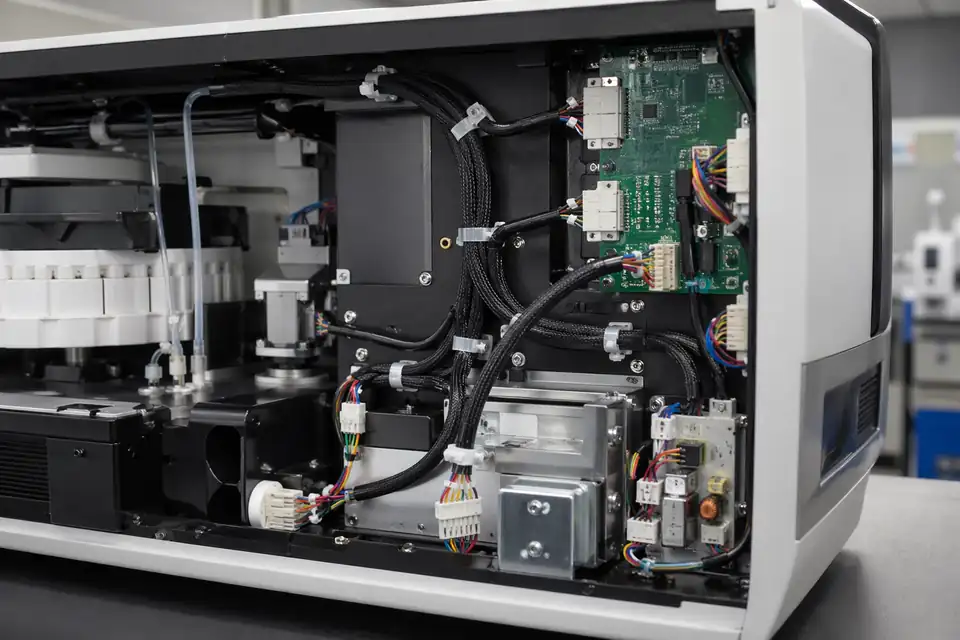
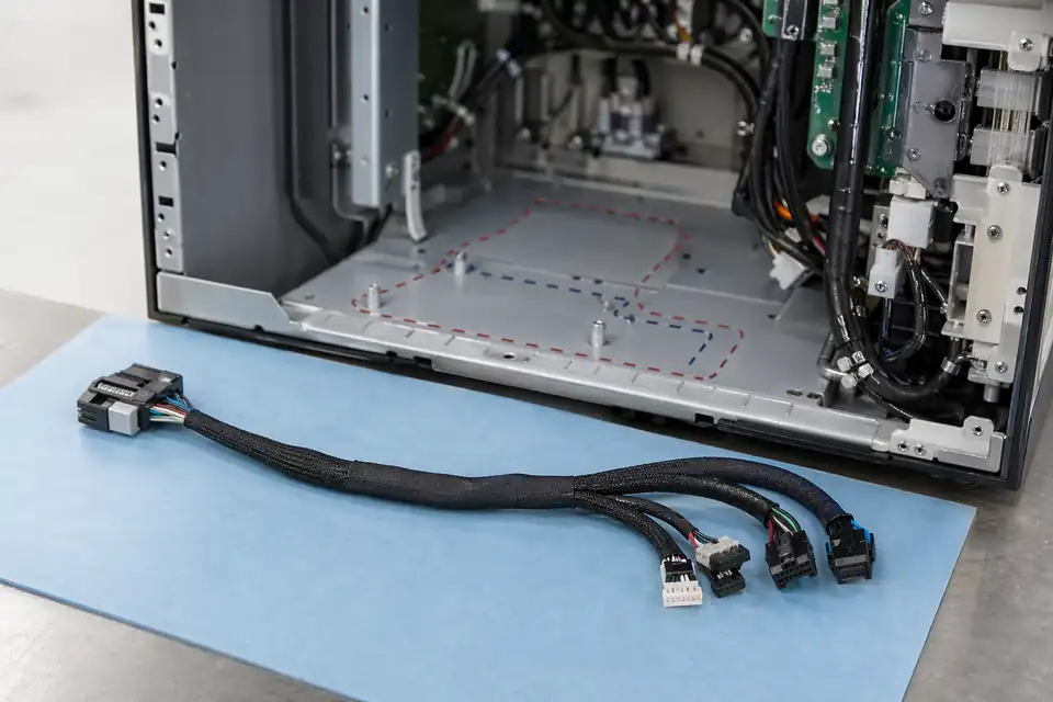
Diagnostic-equipment cable assembly inside a bench-top diagnostic device
Diagnostic-equipment cable assembly inside a test-heavy medical electronics module
Diagnostic-equipment cable assembly in a replacement or maintenance hardware context
Diagnostic Equipment Harness Design Definition Matrix
Internal diagnostic-equipment harnesses are defined by module interfaces, circuit grouping, grounding, route geometry, service access, and device-level validation inputs. Patient leads and ultrasound probe architecture remain outside this route.
| NO | Equipment design input | Harness decision to release | Definition owner or record |
|---|---|---|---|
| 01 | Module interface schedule | Name each analyzer, controller, sensor, pump, display, power, or communication module endpoint and map its connector positions explicitly. | Device interface-control document and point-to-point schedule at the active revision. |
| 02 | Power and signal grouping | Identify circuit function, conductor requirement, grouping, separation, routing priority, and any customer-defined isolation boundary within the equipment. | Approved electrical architecture translated into harness bundle and branch definitions. |
| 03 | Shield, drain, and ground treatment | Specify cable shield construction, drain path, bond endpoint, termination length, floating ends, and chassis references for each applicable circuit. | Grounding and EMC design record owned by the diagnostic equipment program. |
| 04 | Internal route and thermal context | Provide branch path, enclosure clearances, heat-source proximity, moving mechanisms, fixing points, and service loops from the intended equipment layout. | Dimensioned harness drawing cross-referenced to the approved mechanical model. |
| 05 | Service and replacement strategy | Define accessible disconnect points, keyed interfaces, labels, replacement identifier, bend during service, and handling instructions for maintainable modules. | Service-view drawing and device documentation reference supplied by the customer. |
| 06 | Electrical acceptance characteristics | State continuity, resistance, insulation, dielectric, shield, or other checks only with customer limits, test conditions, fixtures, and excluded circuits. | Project validation specification; no universal electrical performance is assigned to the harness family. |
| 07 | Configuration and change control | Tie connector revisions, module versions, optional branches, firmware-dependent interfaces, approved alternates, and deviations to one buildable variant code. | Configuration matrix linking BOM, drawing, device model, and first-article approval. |
First-Party Engineering References
- IEC 60601-1 basic safety and essential performance framework
The diagnostic equipment manufacturer uses the applicable IEC 60601 framework at system level; harness inputs such as insulation, grounding, and routing follow only from its approved design.
- ISO 14971:2019 medical-device risk-management process
Interface, service, misconnections, and electrical hazards are evaluated in the device risk process, which may allocate specific controls to this internal harness.
Diagnostic Equipment Harness Failure-Mode Review
Failure review focuses on internal module correspondence and installed construction. Any effect on diagnosis, alarms, electrical safety, or essential performance must be evaluated and verified by the equipment manufacturer.
| NO | Internal harness failure | Assembly control | Equipment verification handoff |
|---|---|---|---|
| 01 | Connector or branch is routed to the wrong diagnostic module | Use unique interface identifiers, keyed fixture endpoints, complete mapping test, and installed first-article review for the configured equipment variant. | The customer verifies module communication, sensing, control, and fault response in the finished analyzer. |
| 02 | Power and low-level signal conductors are bundled against the approved layout | Make grouping and separation visible on the drawing, branch construction, ties, sleeves, and route checkpoints rather than depending on operator memory. | Noise immunity, measurement accuracy, and thermal performance are system-level validation outcomes. |
| 03 | Shield bond is omitted, duplicated, or landed at an unintended endpoint | Document both physical termination and electrical destination, then inspect preparation and verify the customer-specified shield path electrically. | EMC compliance cannot be concluded from shield continuity on the cable assembly alone. |
| 04 | Service movement transfers force into a terminal or splice | Define service loop, restraint, bend transition, connector access, and any project-specific handling test using the real module arrangement. | Maintenance frequency and acceptable post-service function are established in equipment service validation. |
| 05 | Mixed revision harness fits mechanically but does not match module electronics | Control variant labels, connector populations, optional circuits, BOM status, and first-article identity before release to the line. | Device configuration management decides compatibility and disposition for each equipment revision. |
Diagnostic Equipment Harness Verification Plan
Harness verification proves the released mapping, dimensions, construction, and specified electrical checks. It does not replace finished-equipment tests for diagnostic function, EMC, basic safety, or essential performance.
| NO | Verification activity | Acceptance method | Controlled result |
|---|---|---|---|
| 01 | Complete module-to-module mapping | Test named endpoints, connector positions, splices, optional circuits, required opens, and shield paths against the configured connection schedule. | Electrical mapping report carrying equipment variant and drawing revision. |
| 02 | Route datums and service loops | Measure branch points, free lengths, breakout directions, fixing locations, and service allowance using the released harness datums. | Dimensional record plus disposition of any model or fixture fit observation. |
| 03 | Shield and ground implementation | Inspect coverage, drain preparation, bond hardware, termination location, and measure only the path characteristics stated by the customer. | Shield inspection and test evidence associated with the electrical architecture revision. |
| 04 | Specified electrical characteristics | Run the approved continuity, resistance, insulation, dielectric, or other test with defined circuit groups, limits, dwell, environment, and equipment. | Test report identifying setup, calibration status, results, exclusions, and acceptance source. |
| 05 | Installed configuration sample | Mate the first article to representative modules and review routing, keying, clearance, restraint, label visibility, and service access with the customer. | Joint fit-review record limited to the evaluated equipment configuration. |
| 06 | Production release reconciliation | Compare sample, BOM, drawing, interface schedule, process notes, test program, deviations, and customer approval before closing the baseline. | Released configuration index and first-article approval package. |
Engineering Capability
Diagnostic-equipment harness review ties the module interface map, connector drawings, point-to-point mapping, power and signal grouping, shielding and grounding inputs, route limits, and validation checkpoints to one released definition.
Engineering Capability
Review route path, connector references, and local fit together for the diagnostic-equipment cable build.
Quality and Verification Highlights
Watch local-fit zones, connector exits, and route transitions specific to diagnostic-equipment cable installs.
Evidence Chain
Controlled module-interface and validation basis
Tie connector relationships, point-to-point mapping, module boundaries, validation checkpoints, and the active equipment revision to one released package.
Sample and validation checkpoint record
Record the approved sample, customer-defined checks, release conditions, and installed equipment boundary before pilot or batch introduction.
Batch and revision correspondence
Keep inspection output, batch labels, and shipment records linked to the same diagnostic-equipment revision and approved sample.
Files and Batch Support
Diagnostic-equipment cable work has its own document layer around route and fitting boundaries. Cross-family file control, batch traceability, and certification practice are summarised in the Related Capability Pages.
Diagnostic-equipment cable route and fitting-boundary records
Capture the route path, local fit, and installation-space limits that are specific to the diagnostic-equipment cable build so later structural differences can be traced back to the right layer of change.
Certifications / Records Visuals
IMAGES · 04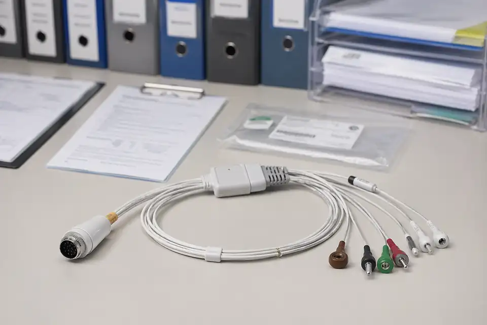
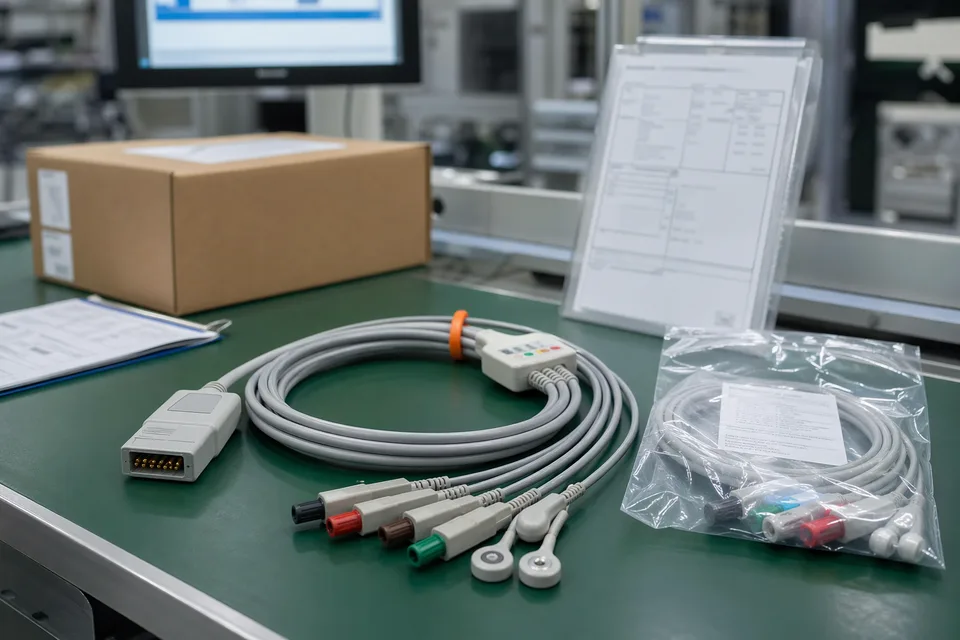
Medical cable assembly compliance and batch-record scene with documents secondary to the harness
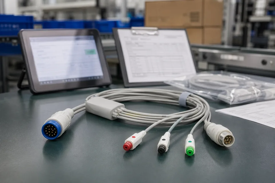
Medical cable compliance record scene with harness sample foreground and controlled documents
Medical cable batch traceability and sample approval archive in clean workspace
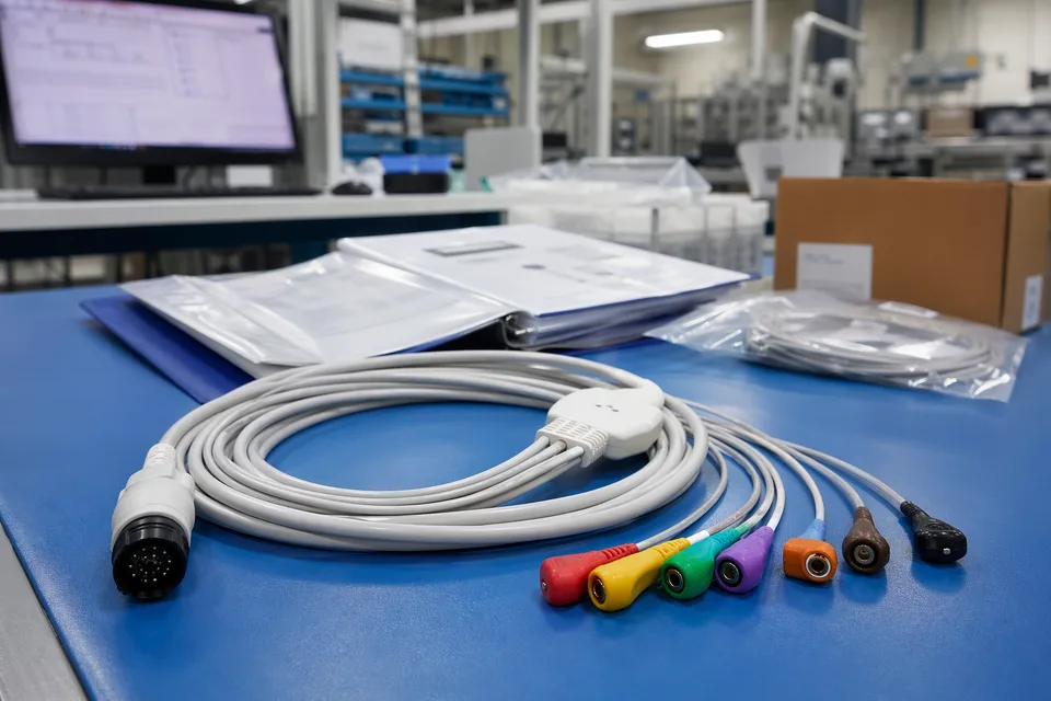
Medical released project folder with connector lot labels and sample cable support context
FAQ
Can you build diagnostic-equipment harnesses from old samples or old parts?
Yes. Existing samples help, but connector mapping, structure limits, validation notes, and active device revision still need to be confirmed before the sample can represent the released build.
What is the minimum input for a diagnostic-equipment quotation?
Send the device type, connector references, pin mapping, validation notes, project stage, and expected quantity.
Why do diagnostic-equipment programs need more than connector model and cable length?
Because structure boundaries, validation rhythm, released files, and version scope often decide whether the assembly can actually be released cleanly.
Can one diagnostic-equipment harness cover several device versions?
Sometimes, but only if mapping definition, structure geometry, validation scope, and revision boundaries stay inside the same approved definition.
Can review start before the full drawing package is complete?
Yes. Early review can start from connector references, validation context, and current structure limits, then tighten as the file package becomes clearer.