Technical Reference · MEDICAL-ULTRASOUND
Ultrasound Probe Interconnects
Custom Medical Ultrasound Probe Cable Manufacturing
High-density fine micro-coax interconnects between diagnostic ultrasound transducers and their system interface
EDPcable manufactures custom ultrasound probe cable assemblies between a transducer assembly and its system interface. The transducer element count, active system-channel architecture, and physical micro-coax or conductor count are separate design inputs; no one-to-one relationship is assumed. Review begins with the approved signal map, conductor construction and gauge, connector interfaces, shield and ground scheme, probe-end geometry, strain relief, and the customer-defined motion and validation plan.
Quick Links
QUICK ACCESSStart with the sections closest to the project structure, interface requirements, and validation scope.
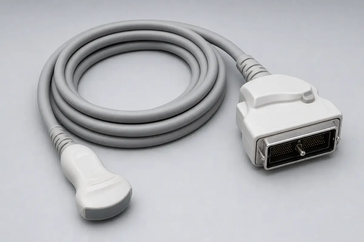
Medical Ultrasound Application Fit Snapshot
Confirm the transducer element definition, active system channels, physical micro-coax or conductor count, signal map, interfaces, shield and ground scheme, and probe-end geometry as separate inputs before sampling.
| NO | Item | Typical Range or Meaning |
|---|---|---|
| 01 | Typical Devices | Console ultrasound probes, portable and handheld probes, specialty probes and transducer arrays |
| 02 | Common Paths | Probe / transducer to console connector, transducer array to front-end board |
| 03 | Key Inputs | Element definition, active channel architecture, physical conductor count and gauge, signal map, shielding and grounding, motion envelope, interfaces |
| 04 | Structural Focus | Probe-end geometry, cable exit, strain relief, conductor layout, and customer-defined motion envelope |
| 05 | Quality Focus | Drawing and signal-map conformance, termination inspection, and project-defined electrical and flex acceptance |
| 06 | Recommended Related Pages | Micro medical harnesses, diagnostic equipment cables, cleanroom medical interconnect manufacturing |
Application Fit
Ultrasound cable review starts with the transducer-side and system-side interfaces plus an approved signal map. Element count, active channel architecture, and physical conductor count may differ because of multiplexing, grounding, shielding, auxiliary functions, or internal electronics. The released cable definition must state the actual conductors and their assignments.
| NO | Application Scene | Primary Needs | Common Risks |
|---|---|---|---|
| 01 | Console ultrasound probes | Approved signal map, connector interfaces, flexible cable body | Incorrect channel assignment, conductor damage at the cable exit |
| 02 | Portable / handheld probes | Defined cable mass, motion envelope, and strain-relief geometry | Cable-body stiffness, tight bends, unsupported pull loads |
| 03 | Specialty probes (endocavity / transesophageal) | Project-defined diameter, materials, cleaning inputs, and routing | Probe-end space, material assumptions, conductor layout |
| 04 | Transducer array to front end | Controlled conductor assignment, shielding, and grounding | Signal-map errors, shield or ground discontinuity, crosstalk |
| 05 | Replacing legacy probe cables | Current interface, signal map, materials, and revision correspondence | A legacy sample may not represent the current released design |
Customer Pain Points
An ultrasound probe name alone does not define the cable. Quotations and samples need the actual conductor assignments, connector references, probe-end geometry, and validation conditions.
| NO | Customer Pain Point | Risk in Ultrasound Probe Programs | What Needs Early Confirmation |
|---|---|---|---|
| 01 | Product design issues | Element, channel, and conductor quantities are treated as interchangeable, producing an incorrect cable definition | Element definition, active channel architecture, physical conductor count, signal map |
| 02 | Product quality issues | Incorrect assignments or shield and ground execution can contribute to channel faults, crosstalk, or imaging artifacts | Approved signal map, shield and ground scheme, project-defined electrical checks |
| 03 | After-sales issues | An undefined motion profile can overload the cable exit or conductors | Motion path, bend radius, speed, cycle target, fixture, temperature, monitored circuits, failure criteria |
| 04 | Complaint-handling issues | A fault is difficult to isolate between the transducer, cable, connector, and system electronics | Approved sample, system test method, installation record, revision record |
Application Scene Visuals
IMAGES · 04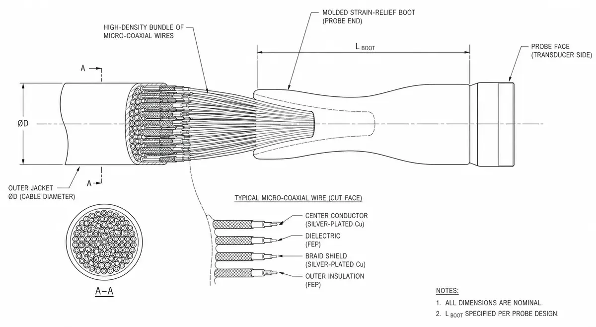
Probe-end high-density fine-coax bundle with strain-relief structure
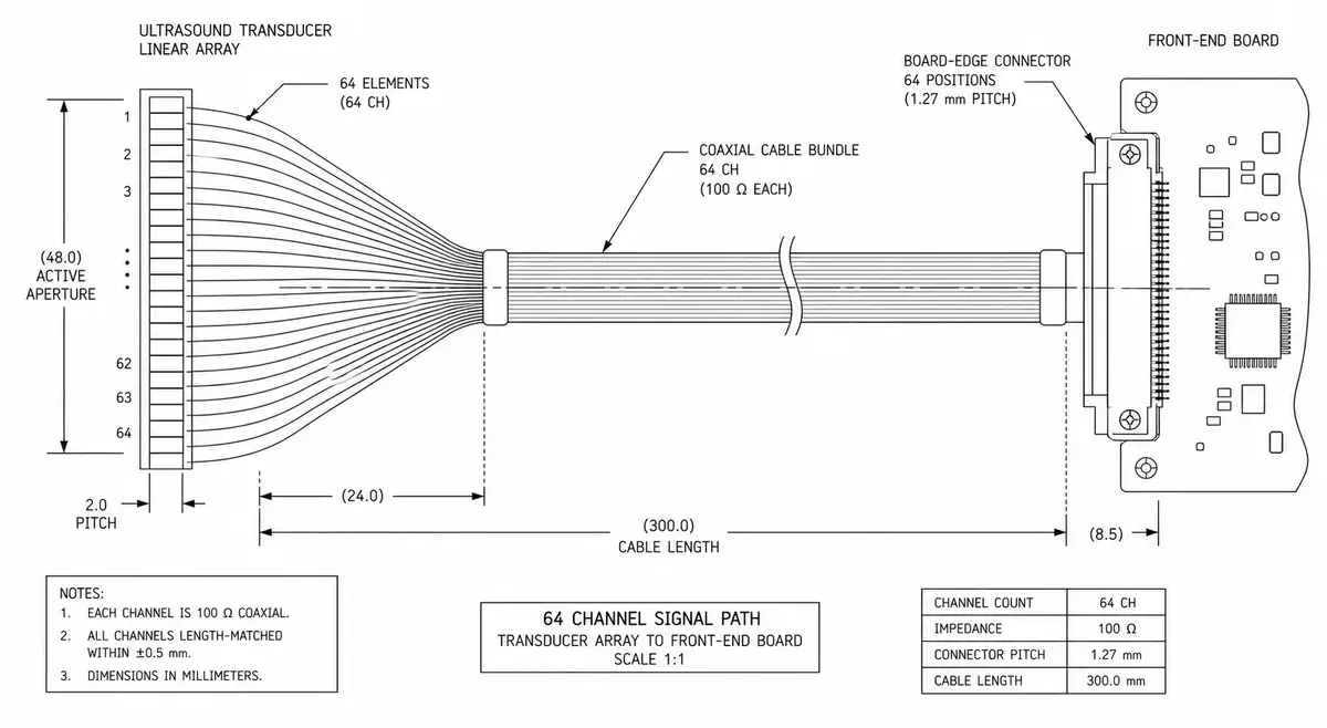
Multi-channel path from transducer array to front-end board
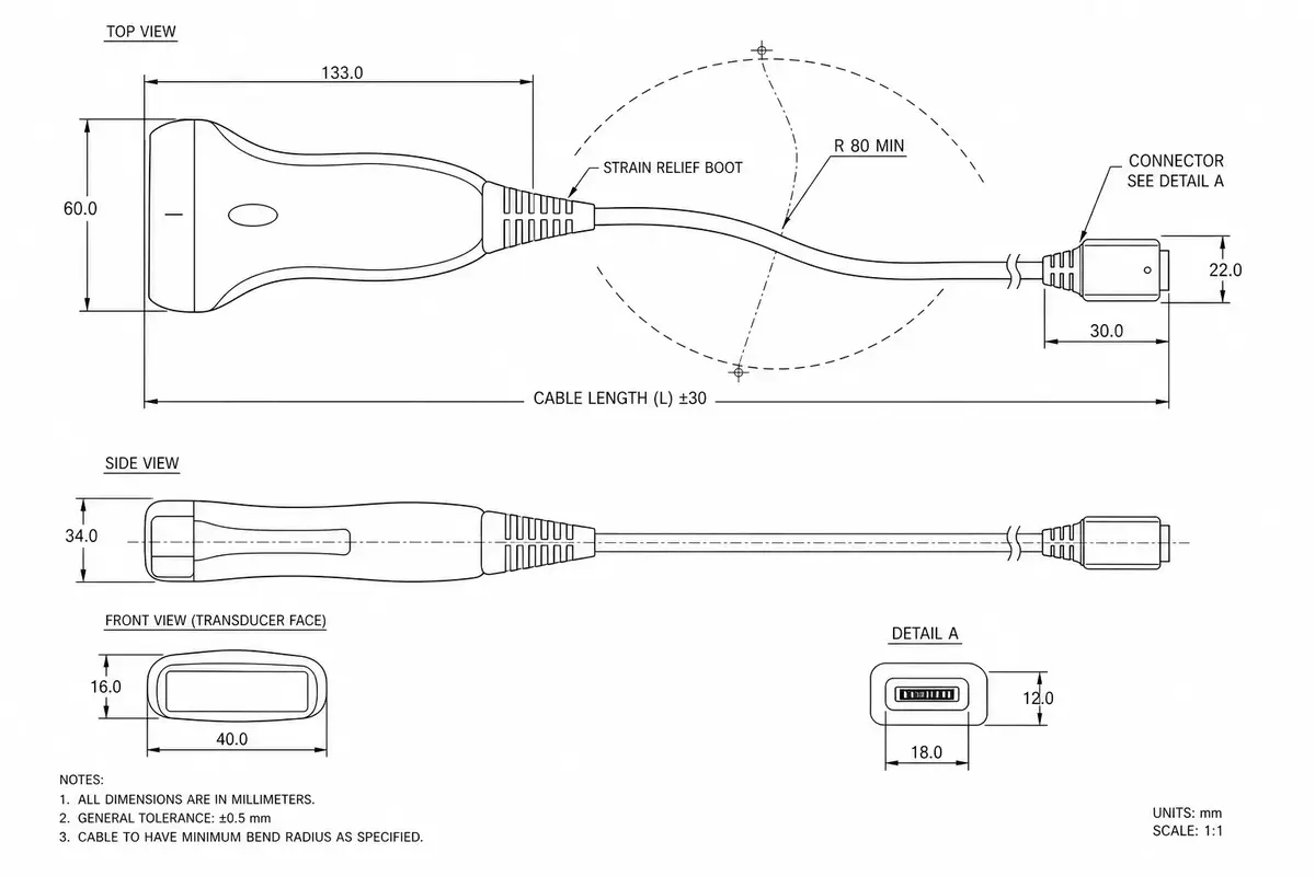
Flexible cable-body routing on a portable ultrasound probe
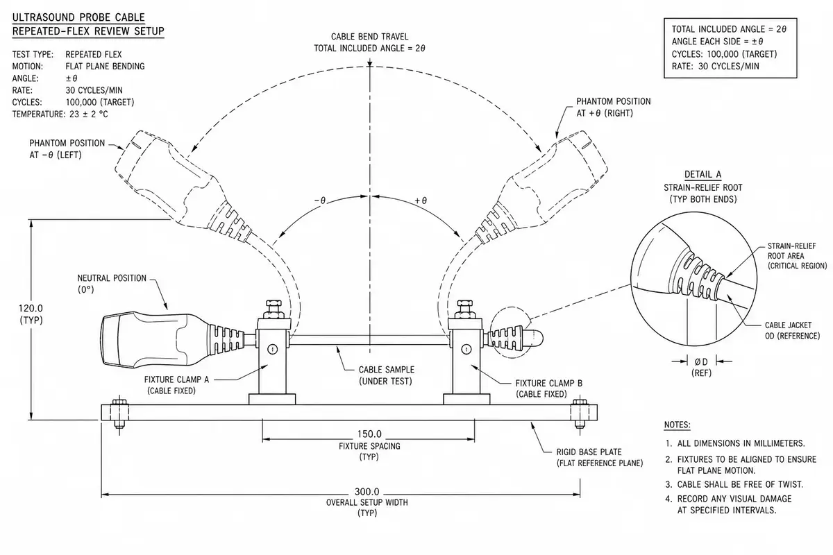
Probe-cable repeated-flex and revision review detail
Medical Ultrasound Probe Cable Design Definition Matrix
An ultrasound probe cable is defined from the transducer architecture, active channels, physical conductors, signal map, shielding, probe-end mechanics, and validation protocol. Imaging performance belongs to the complete probe and ultrasound system.
| NO | Ultrasound design input | Cable-assembly definition | Authoritative project record |
|---|---|---|---|
| 01 | Transducer elements and active channels | Record element definition and active system-channel architecture separately, then state how multiplexing or electronics map them into cable circuits. | Customer transducer and front-end architecture, not an assumed one-to-one conductor rule. |
| 02 | Physical conductors and micro-coax construction | Specify conductor or coax count, gauge, dielectric, shield, jacket, grouping, and approved manufacturer references for the actual probe model. | Released cable BOM and construction drawing with controlled alternates. |
| 03 | Signal and return-path map | Define every signal, return, ground, shield, drain, power, control, and unused circuit between transducer assembly and system connector. | Revision-controlled signal schedule approved by probe and system engineering. |
| 04 | Shield and grounding architecture | Set individual and overall shield treatment, coverage requirement, drain paths, connector bonds, probe-end termination, and floating endpoints from the electrical design. | Device-owned grounding and signal-integrity specification tied to the selected construction. |
| 05 | Probe exit and strain-relief geometry | Define exit direction, local stack, bond or overmold interfaces, transition length, support, profile, and permissible force path at the probe body. | Dimensioned probe-end drawing and representative mechanical sample. |
| 06 | Motion and handling envelope | Describe bend locations, radius, travel, torsion, pull, speed, cycles, temperature, cleaning state, monitored circuits, and failure criteria as one protocol. | Customer-approved use simulation limited to the exact probe cable geometry and BOM. |
| 07 | System connector and model revision | Freeze connector part numbers, keying, cavity population, backshell, shield bond, cable exit, model compatibility, and legacy replacement boundary. | Interface-control record that identifies probe and console configurations represented by the sample. |
First-Party Engineering References
- IEC 60601-1 medical electrical equipment general requirements
Applicable safety and essential-performance requirements are selected and verified by the ultrasound equipment manufacturer; cable construction data supports but does not complete that evaluation.
- ISO 14971:2019 risk management for medical devices
Probe hazards, foreseeable handling, signal loss, misconnections, cleaning, and residual risk are addressed in the manufacturer's device risk process, which allocates cable controls as needed.
Medical Ultrasound Probe Cable Failure-Mode Review
High circuit density makes mapping, micro-coax termination, return paths, probe exits, and revision control central to the assembly review. Diagnostic image effects require system-level investigation and validation.
| NO | Probe-cable failure condition | Assembly prevention or detection | Ultrasound-system boundary |
|---|---|---|---|
| 01 | Element, channel, and physical conductor assumptions produce an incorrect map | Require an approved signal schedule that separates the three quantities, then test named endpoints and any multiplexed or shared paths explicitly. | The probe designer verifies channel operation and image formation in the intended system. |
| 02 | Micro-coax termination damages center conductor, dielectric, or shield | Control preparation and termination for the exact coax and contact combination, with project-defined magnification, dimensions, and sample evidence. | Acceptable electrical effects and inspection depth are established by the probe engineering plan. |
| 03 | Shield or return-path discontinuity changes the released electrical construction | Document each bond and shield endpoint, inspect physical preparation, and run only the specified continuity or impedance-related check with the approved fixture. | Noise, crosstalk, and image-quality conclusions require representative probe and console validation. |
| 04 | Probe-exit motion concentrates stress at a bond or termination zone | Keep moving length outside protected transitions and test the released exit geometry under the customer's defined motion and load profile. | Durability applies only to the tested fixture, materials, cycles, environment, and pass criteria. |
| 05 | Legacy probe cable mates but carries a different signal or shield revision | Control model identifiers, keyed interfaces, signal-map revision, conductor population, backshell, and first-article identity before replacement approval. | The ultrasound manufacturer decides cross-model compatibility and confirms system function. |
Medical Ultrasound Probe Cable Verification Plan
Verification proves the cable matches the approved architecture and tested mechanical condition. Frequency response, acoustic output, imaging quality, and medical safety cannot be inferred from harness inspection alone.
| NO | Verification subject | Defined method and boundary | Evidence delivered |
|---|---|---|---|
| 01 | Signal-map and conductor correspondence | Test every specified signal, return, ground, shield, power, control, splice, and open circuit between named transducer and system endpoints. | High-density mapping report referencing signal schedule and connector revisions. |
| 02 | Micro-coax termination construction | Inspect preparation length, center-conductor joint, dielectric condition, shield treatment, spacing, contamination, and support to the approved criteria and magnification. | Termination inspection record identified to coax type, process revision, and sample location. |
| 03 | Customer-specified electrical characteristics | Measure only defined continuity, resistance, isolation, impedance, loss, crosstalk, or shield characteristics with stated fixture, reference plane, frequency range, limits, and environment. | Electrical report containing setup, calibration, traces or readings, sample identity, and acceptance source. |
| 04 | Shield and ground implementation | Confirm physical bond locations and verify specified electrical paths from probe end through cable shields and system connector hardware. | Ground-path inspection and test record tied to the released architecture. |
| 05 | Probe-exit motion sample | Run the approved bend, torsion, pull, or combined motion profile while monitoring named circuits and inspecting the protected transition after test. | Mechanical validation result limited to the documented fixture, BOM, geometry, and exposure. |
| 06 | Representative system handoff | Supply configuration-controlled cable samples for customer probe and console testing, with deviations and assembly evidence available for correlation. | Customer-owned imaging and device validation report cross-referenced to the harness first article. |
Engineering Capability
Engineering review connects the transducer definition and active-channel architecture to the physical conductor map, interfaces, shield and ground scheme, and probe-end mechanical design before release.
Engineering Capability
Record the element definition, active system channels, and physical conductors separately, then use the approved signal map to connect them.
Define cable exit, strain relief, supported pull loads, and any motion test together; cyclic claims apply only to the specified fixture and acceptance plan.
For legacy replacements or multiple probe models, identify which interface, signal-map, material, and mechanical revisions each approved sample represents.
Quality and Verification Highlights
Conductor count, assignments, shield and ground paths, termination appearance, and probe-end geometry are checked to the approved definition.
Continuity, resistance, isolation, signal, or shielding checks are included only where the customer supplies the limits and method.
Flex or pull acceptance requires a defined fixture, load or motion, bend radius, cycle target, environment, monitored circuits, and pass or fail criteria.
Evidence Chain
Signal-map and conductor records
Record element and active-channel references separately from the physical conductor map, interface revisions, and approved sample numbers.
Strain-relief and end-section check records
Record probe-end geometry, strain relief, shield and ground execution, termination inspection, and any project-defined pull or flex result.
Sample-to-small-batch transition basis
Link sample approval, validation conditions, authorized changes, and the production revision boundary.
Systems, Records, and Material Compliance
Quality-system and material evidence is supplied within the scope of the customer-approved project requirements.
ISO 13485 quality system
For probe-cable assemblies, the ISO 13485 quality system supports revision control, material and lot traceability, documented termination processes, inspection evidence, and approved change handling.
Material compliance position
Requested declarations or material evidence are confirmed against the selected materials and project documents. Cleaning, sterilization, patient-contact, and biocompatibility acceptance remain customer-defined.
Sample and inspection records
First-article, appearance, conductor-assignment, and project-defined electrical or mechanical records map to the current revision.
Batch labels and shipment documents
Batch labels, carton marks, packing information, and agreed shipment-side documents are supported.
Certifications / Records Visuals
IMAGES · 04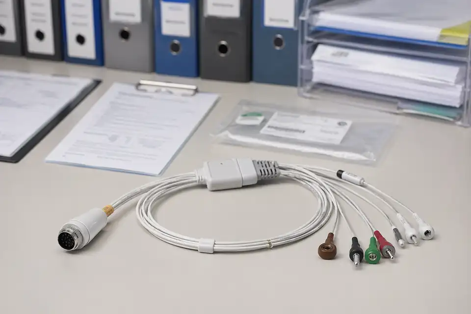
Medical cable assembly compliance and batch-record scene with documents secondary to the harness
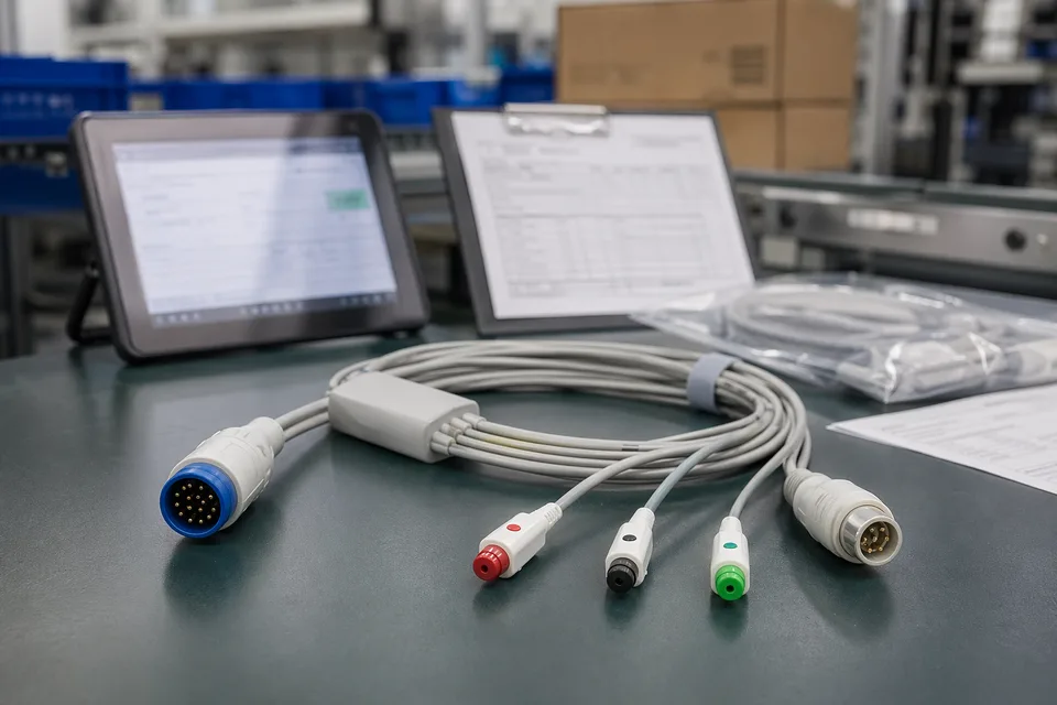
Medical cable compliance record scene with harness sample foreground and controlled documents
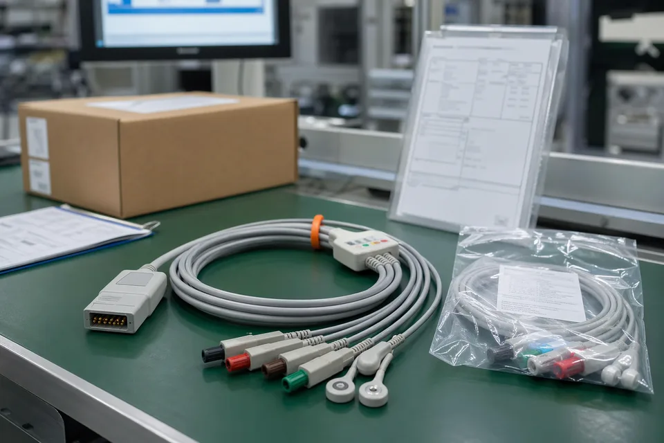
Medical cable batch traceability and sample approval archive in clean workspace
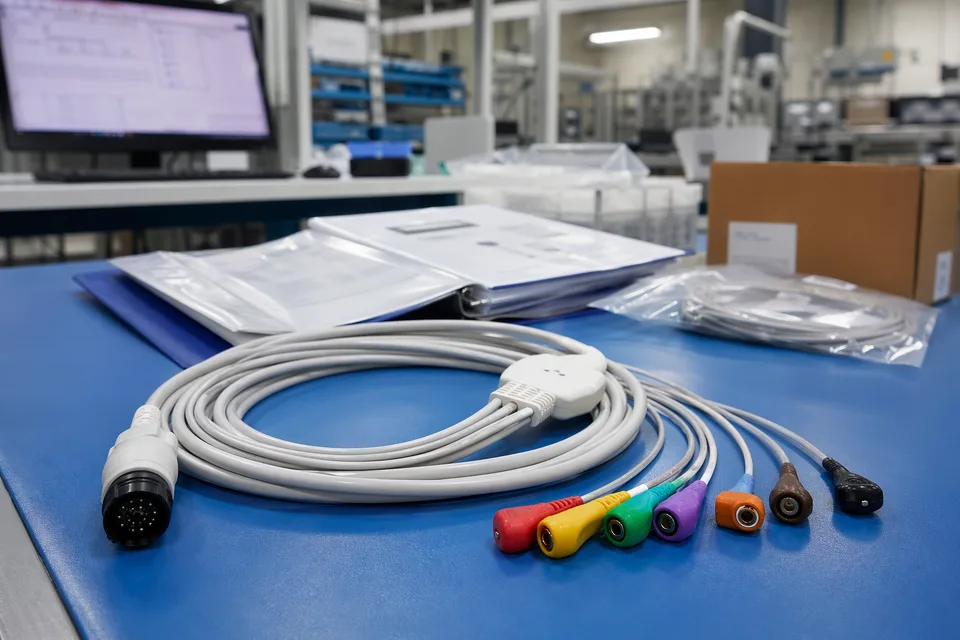
Medical released project folder with connector lot labels and sample cable support context
FAQ
What is the minimum input for an ultrasound probe cable quotation?
Send the transducer element definition, active system-channel architecture, physical micro-coax or conductor count and gauge, approved signal map, interfaces, length, shield and ground scheme, probe-end geometry, motion conditions, project stage, and quantity.
Are element count, system-channel count, and micro-coax count the same?
Not necessarily. Elements describe the transducer array, active channels describe the system architecture, and physical micro-coaxes or conductors describe the cable. Supply the approved signal map rather than assuming a one-to-one relationship.
Can you rebuild a legacy probe cable?
A legacy sample can support evaluation, but it does not establish the current signal map, interfaces, materials, conductor construction, motion conditions, or revision. Those inputs still require customer approval.
Can cleaning, sterilization, or biocompatibility requirements be included?
Yes, when the customer provides the applicable substances, exposure method, cycles, material restrictions, test standard, and acceptance evidence. No cleaning compatibility, sterilization suitability, patient-contact classification, or biocompatibility claim is implied without those project documents.
Do you have a medical quality system?
Yes. Ultrasound probe-cable work is managed within EDPcable's ISO 13485 quality system for controlled documentation, traceability, process records, inspection, and change review; device approval remains outside the cable supplier's scope.