Technical Reference · ECG-LEAD-WIRE
ECG Lead-Wire Interconnects
Custom ECG Trunk Cable and Lead Wire Manufacturing
For ECG trunk-cable and lead-wire-set OEM programs across patient monitoring, telemetry, and diagnostic ECG equipment
EDPcable provides custom manufacturing for ECG trunk cables and lead-wire sets used between patient electrodes and monitoring or diagnostic equipment. Define the clinical lead configuration, number of physical lead wires and electrode connections, monitor channel and interface requirements, termination style, customer-specified color and identification scheme, shielding, protective-component requirements, and active revision separately. These quantities and functions are related but are not interchangeable.
Quick Links
QUICK ACCESSStart with the sections closest to the project structure, interface requirements, and validation scope.
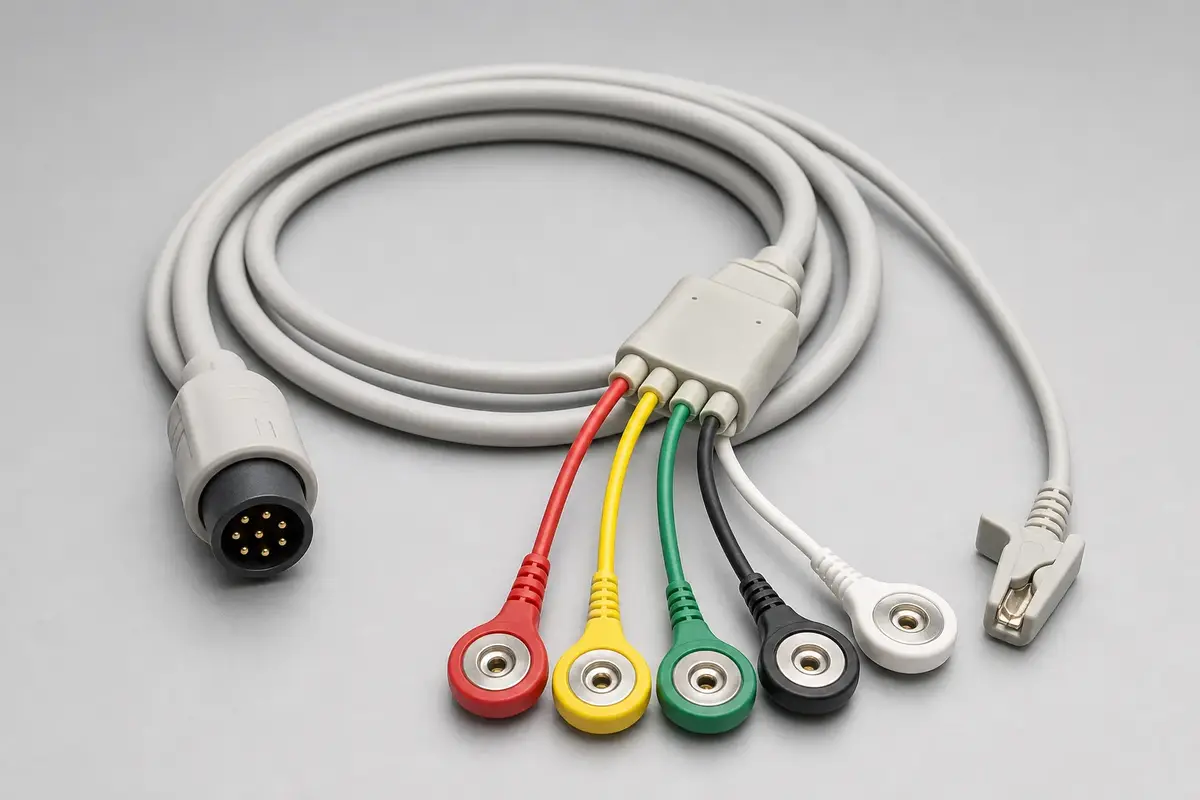
ECG Lead-Wire Application Fit Snapshot
Confirm the clinical lead configuration, physical lead-wire and electrode-connection count, monitored-channel requirement, terminations, identification scheme, and target interface before sampling. Do not infer one quantity from another.
| NO | Item | Typical Range or Meaning |
|---|---|---|
| 01 | Typical Devices | Bedside monitors, telemetry monitoring, diagnostic ECG, portable ECG units |
| 02 | Common Structures | Trunk cable plus lead wire set, built as one piece or as separable parts |
| 03 | Key Inputs | Clinical lead configuration, physical lead-wire count, electrode terminations, monitor channels and interface, customer-specified identification scheme, shielding, protective-component requirements |
| 04 | Standard Conventions | Identification and safety-construction inputs follow the customer-specified standard, drawing revision, and device-level validation plan |
| 05 | Quality Focus | Consistent identification and mapping, project-defined termination pull and flex checks, batch correspondence |
| 06 | Recommended Related Pages | Patient monitoring cables, portable medical cables, micro medical harnesses |
Application Fit
ECG review starts with the clinical lead configuration, physical lead-wire set, electrode terminations, and monitor interface. Each branch must follow the approved mapping and identification scheme, while handling and flex requirements remain project-defined.
| NO | Application Scene | Primary Needs | Common Risks |
|---|---|---|---|
| 01 | Bedside monitoring ECG | Customer-defined physical lead-wire set, identification, and handling conditions | Confusing clinical leads, physical wires, channels, or identification schemes |
| 02 | Telemetry / wearable monitoring | Lightweight, flexible, resistant to motion interference | Shielding and motion artifacts, termination fatigue |
| 03 | Diagnostic ECG acquisition | Customer-defined electrode connections, physical lead-wire set, and clinical lead configuration | Treating displayed or derived leads as the physical wire count |
| 04 | Portable / emergency ECG | Rugged, quick to connect, tolerant of repeated mating | Termination pull strength, connector life |
| 05 | Replacing legacy lead wires | Faithful rebuild plus interface correspondence | The old part does not necessarily match the current monitor interface |
Customer Pain Points
ECG RFQs stall when clinical lead configuration, physical lead-wire count, electrode terminations, monitor channels, identification scheme, or interface revision are left implicit.
| NO | Customer Pain Point | Risk in ECG Lead-Wire Programs | What Needs Early Confirmation |
|---|---|---|---|
| 01 | Product design issues | Physical lead-wire set, electrode termination, or interface does not match the approved monitor configuration | Clinical lead configuration, physical wire count, electrode connections, monitor channels, terminations, interface |
| 02 | Product quality issues | Mapping or identification differs from the approved scheme, or terminations miss the project acceptance criteria | Customer-specified scheme and revision, mapping, project-defined pull check, first-article confirmation |
| 03 | After-sales issues | Lead wires break at the root after repeated handling and flexing | Project-defined bend path, cycle conditions, strain relief, acceptance criteria, revision records |
| 04 | Complaint-handling issues | Abnormal readings are hard to attribute to the lead wire, the electrode, or the monitor | Sample approval, installation records, revision records |
Application Scene Visuals
IMAGES · 04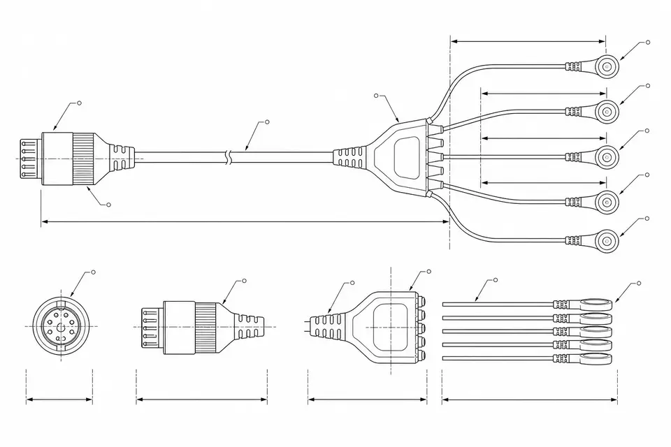
ECG trunk cable branching into a multi-lead wire set with monitor-end connector
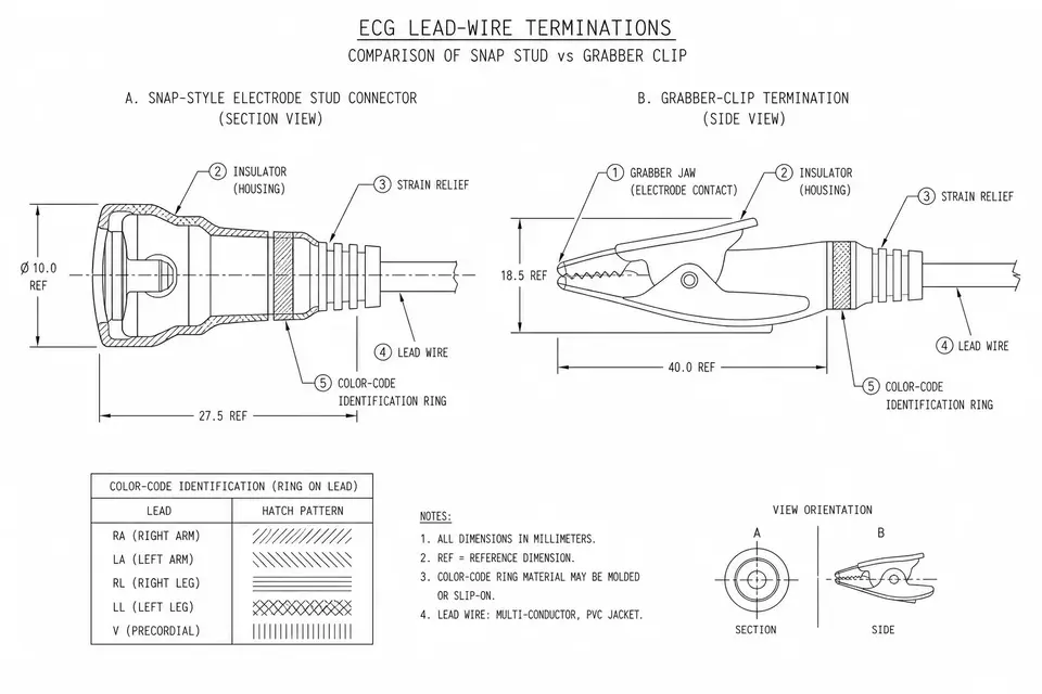
Snap and clip ECG lead terminations with color-coding detail
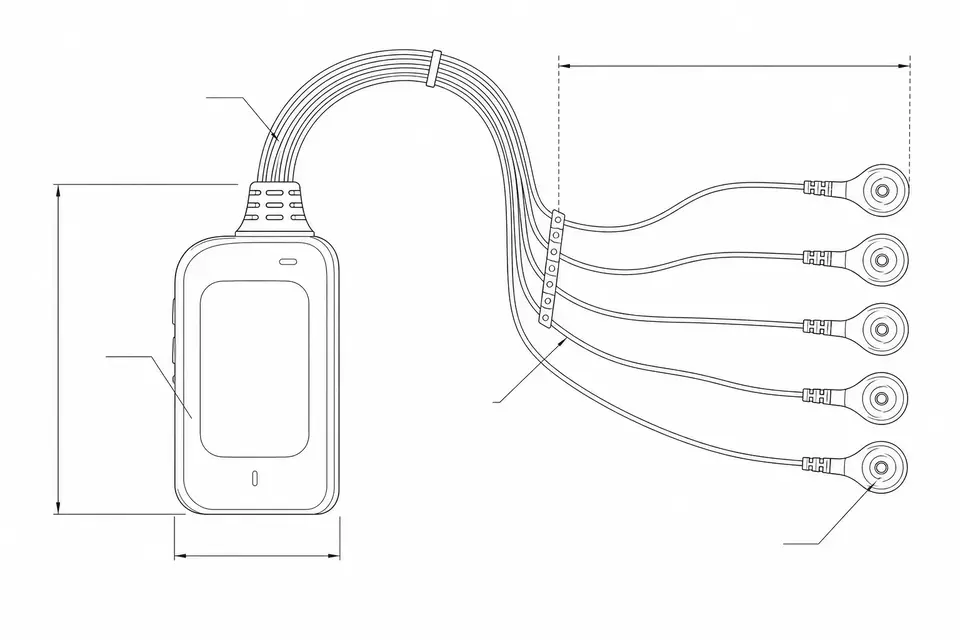
Compact lead-wire routing for telemetry and portable ECG units
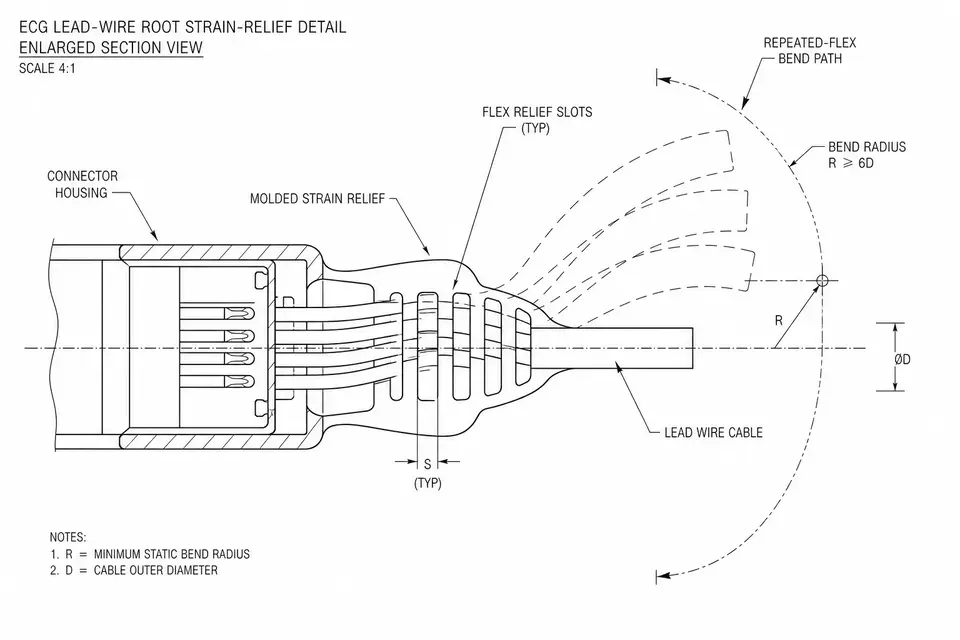
Lead-wire root strain relief and repeated-flex review detail
ECG Trunk Cable and Lead-Wire Design Definition Matrix
Define clinical lead configuration, physical lead wires, electrode interfaces, monitor channels, identification, and protective structure as separate inputs. The cable build cannot by itself demonstrate ECG diagnostic accuracy or medical electrical safety.
| NO | ECG program input | Cable-set decision | Controlled source |
|---|---|---|---|
| 01 | Clinical lead configuration | Name the intended lead system and map each clinical designation to the customer-approved electrode and monitor-channel architecture without assuming physical wire count. | Device clinical and electrical definition supplied by the monitor manufacturer. |
| 02 | Physical lead wires and electrode ends | List every lead wire, trunk branch, electrode connection, snap, clip, grabber, or other termination with exact mating and replacement requirements. | Lead-set drawing and BOM separated from clinical terminology. |
| 03 | Monitor interface and channel map | Freeze connector manufacturer part numbers, cavity assignments, channel correspondence, keying, shield contacts, and any legacy replacement reference. | Revision-controlled point-to-point schedule verified against the intended monitor interface. |
| 04 | Identification convention | Specify customer-selected color, marking, lead labels, symbols, language, location, and market convention for every patient-end connection. | Approved identification artwork and inspection master; no convention is selected by assumption. |
| 05 | Protective and insulation structure | Define any current-limiting component, insulation system, creepage-related geometry, shield, barrier, or material requirement allocated by the device safety design. | Exact BOM and device-owned safety specification, not a generic cable rating. |
| 06 | Flex, pull, and cleaning conditions | State bend path, moving length, radius, load, cycles, agent, exposure, monitored circuits, and acceptance criteria for each required use simulation. | Customer validation protocol tied to cable materials, termination geometry, and intended reuse. |
| 07 | Trunk split and strain-relief geometry | Set trunk length, lead lengths, yoke or breakout, cable exit, support zones, overmold, and no-load regions from actual user handling and storage. | Dimensioned construction drawing plus representative fit or handling sample. |
First-Party Engineering References
- IEC 60601-1 general requirements for basic safety and essential performance
The responsible equipment manufacturer determines applicable general and particular IEC 60601 requirements; the ECG cable set is built to the construction requirements allocated by that manufacturer but is not independently approved by this reference.
- IPC/WHMA-A-620E cable and harness workmanship reference
When invoked by contract, IPC/WHMA-A-620E can support termination and workmanship acceptance, while ECG mapping, protective design, inspection frequency, and clinical validation remain project-specific.
ECG Trunk Cable and Lead-Wire Failure-Mode Review
Assembly controls must preserve mapping, identification, terminations, and the released protective construction. Clinical impact and residual risk are assessed in the monitor or diagnostic system's formal risk process.
| NO | Cable-set failure condition | Manufacturing or inspection control | System-level closure |
|---|---|---|---|
| 01 | Clinical label and electrical channel correspondence disagree | Derive both markings and cavity mapping from one approved schedule, then verify every labeled patient end to its named monitor position. | The device maker confirms displayed lead identity, fault response, and intended clinical function. |
| 02 | Customer identification convention is mixed between markets or revisions | Control artwork, color materials, labels, packaging identifiers, and variant segregation with a first-article reference for each released scheme. | Market and usability acceptability are decided in the manufacturer's regulatory and use-related validation. |
| 03 | Electrode termination or trunk breakout transfers user load into conductors | Define local support and apply the customer-specified pull or flex method to representative terminations without substituting an arbitrary universal value. | Expected use, misuse, replacement interval, and post-test function are device-program inputs. |
| 04 | Shield, drain, or protective component differs from the approved circuit | Use exact component identity, orientation controls, electrical mapping, and visual or measured checks named in the released inspection plan. | Leakage, defibrillation protection, EMC, and other safety functions require complete-system verification where applicable. |
| 05 | Cleaning exposure degrades insulation, overmold, label, or electrode interface | Test the exact material and termination set under the defined agent, duration, cycles, drying, and acceptance observations. | Reusable-device cleaning validation and biological evaluation are owned by the legal manufacturer. |
ECG Trunk Cable and Lead-Wire Verification Plan
The verification record links physical patient ends, labels, monitor positions, protective components, and mechanical samples to one approved revision. Device accuracy and medical electrical safety remain separate validation activities.
| NO | Verification element | Execution and acceptance basis | Documented evidence |
|---|---|---|---|
| 01 | Labeled patient-end to monitor-position mapping | Perform complete point-to-point testing using clinical designation, physical lead identifier, electrode termination, and connector cavity from the same schedule. | Mapping report that makes clinical labels and electrical endpoints auditable. |
| 02 | Identification scheme conformity | Inspect color, symbol, wording, language, location, orientation, durability requirement, and packaging variant against approved customer artwork. | Variant-specific identification record associated with the destination market and revision. |
| 03 | Termination and breakout strength sample | Apply only the defined pull direction, rate, fixture, sample size, limit, and post-test inspection to electrode ends, connector ends, or yokes. | Mechanical result limited to the tested termination and material construction. |
| 04 | Defined flex or handling simulation | Run the customer protocol with stated bend path, radius, travel, load, cycles, cleaning state, electrical monitoring, and failure criteria. | Test record listing fixture, sample BOM, conditions, interruptions, and post-test findings. |
| 05 | Shield and protective-component correspondence | Inspect and electrically confirm only the shield paths, component values, orientation, and circuit limits stated in the device-approved specification. | Construction and electrical evidence tied to exact protective-component lots where required. |
| 06 | Device-side safety and function handoff | Provide approved cable samples and assembly records for the manufacturer's system tests without representing those tests as cable-supplier certification. | Customer-owned validation report plus harness release cross-reference if the customer returns that report for inclusion in the project file. |
Engineering Capability
ECG lead-wire engineering fixes the clinical lead configuration, physical lead-wire and electrode-connection count, monitor channels and interface, terminations, mapping, identification scheme, shielding, and strain relief in one released definition.
Engineering Capability
State clinical lead configuration, physical wires and electrode connections, and monitor channels separately; record the customer-specified identification scheme and revision in the drawing.
Review terminations, strain relief, and flex conditions together using the customer's bend path, cycle definition, pull method, and acceptance criteria.
Write the monitor-interface correspondence down before sampling: state the target monitor interface and whether the build replaces a legacy part.
Quality and Verification Highlights
The focus is mapping, identification, and termination consistency against the approved scheme, drawing revision, and project-defined pull criteria.
Inspection records map back to the lead definition: first-article confirmation, continuity, color, and termination checks should all reference the same drawing revision.
Safety-structure alignment is validated at device level: current-limiting and insulation structures can be built to requirement, with final safety validation owned by the device maker and the customer.
Evidence Chain
Lead and marking confirmation records
Tie the clinical lead configuration, physical lead-wire set, monitor channels, mapping, identification scheme, terminations, and sample numbers together.
Termination and strain-relief check records
Record the customer-defined pull method, bend path, cycle conditions, root strain relief, monitored circuit, and acceptance criteria.
Sample-to-small-batch transition basis
Write down the sample approval, change records, and the small-batch revision boundary.
Systems, Standards Alignment, and Brand Boundaries
Credibility in an ECG lead-wire program comes from the quality system, traceable records, and a clear position on standards and brands.
ISO 13485 quality system
For this ECG route, the ISO 13485 quality system supports controlled drawings, approved materials, lot linkage, inspection records, deviations, and revision-specific release evidence.
Standards alignment
Identification and construction inputs can be reviewed against the customer-specified AAMI, IEC, or other applicable requirements and revision; final safety validation remains with the device maker and customer.
Material compliance
The customer defines skin-contact classification, restricted-substance requirements, material evidence, cleaning exposure, and the biocompatibility validation plan for the device program.
Brand boundaries
Third-party monitor brand names are used only to identify interface pairing; the products are compatible cables independently manufactured by EDPcable, with no authorization from or affiliation with the brand owners.
Certifications / Records Visuals
IMAGES · 04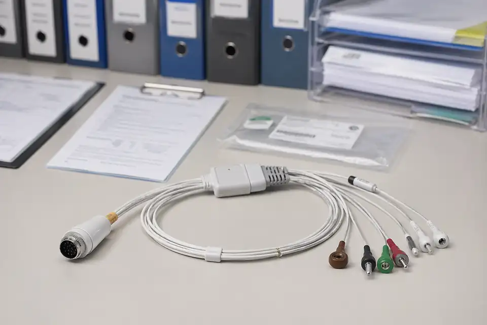
Medical cable assembly compliance and batch-record scene with documents secondary to the harness
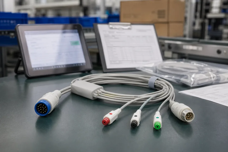
Medical cable compliance record scene with harness sample foreground and controlled documents
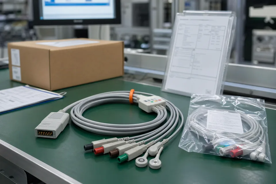
Medical cable batch traceability and sample approval archive in clean workspace
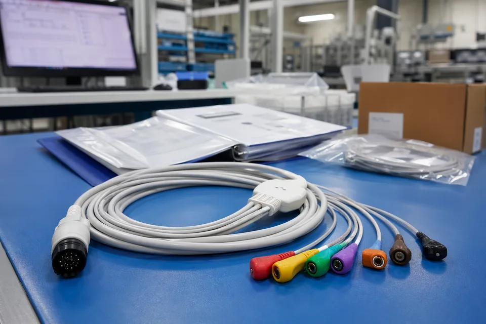
Medical released project folder with connector lot labels and sample cable support context
FAQ
What is the minimum input for an ECG lead-wire quotation?
Send the clinical lead configuration, physical lead-wire and electrode-connection count, monitor channels and interface, termination style, customer-specified identification scheme and revision, shielding, project stage, and expected quantity.
How does ECG lead-wire cabling differ from a device-side monitoring harness?
ECG lead-wire cabling covers the patient-contact trunk and physical lead-wire set, including electrode terminations and identification. Patient-monitoring harnesses cover device-side or host-side interconnects in the monitor equipment.
Which standard do colors and marking follow?
The customer specifies the AAMI, IEC, AHA, or other approved identification scheme and its revision. The selected scheme, mapping, and labels are then fixed in the drawing; schemes are not assumed to be interchangeable.
How are safety, cleaning, and biocompatibility requirements handled?
The customer defines the applicable safety construction, cleaning exposure, skin-contact classification, material evidence, and biocompatibility validation plan. Feasibility and requested records are reviewed against those project documents; no cable-level clinical conclusion is implied.
Do you have a medical quality system?
Yes. EDPcable's ISO 13485 quality management system governs document control, material and lot traceability, process records, inspection, and change handling for ECG cable work within the agreed manufacturing scope.