Technical Reference · SHIELDED-ROUTING
Shielded LVDS Interconnect
LVDS Harnesses with Project-Defined Shield and Ground Paths
Engineer the shield as part of the enclosure return path, not as a generic cable option
Shield material alone cannot predict LVDS system EMC performance. EDPcable reviews the actual aggressors, pair construction, shield coverage, drain or shell termination, circuit and chassis bonds, exposed connector transitions, route separation, fixing, enclosure state, and compliance test plan as one installed configuration.
Quick Links
QUICK ACCESSStart with the sections closest to the project structure, interface requirements, and validation scope.
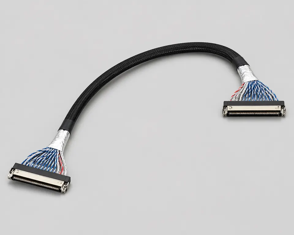
Shield and Return-Path Release Inputs
Use this page when the endpoint map is already controlled and shielding is a release constraint. First identify the noise environment and equipment grounding decision, then define every cable, connector-transition, route, and enclosure boundary.
| NO | Release field | Project definition |
|---|---|---|
| 01 | Typical Use | LVDS display systems with documented switching supplies, motors, radios, external ports, or dense internal routes |
| 02 | Key Inputs | Endpoint connectors and map, aggressor locations, pair construction, shield material, drain or shell path, and grounding architecture |
| 03 | Engineering Focus | Maximum exposed transition, endpoint bonds, keep-out spacing, route crossings, bend stiffness, fixing, and enclosure state |
| 04 | Quality Focus | Construction audit, defined bond measurements, route inspection, functional stress, equipment EMC, and post-test teardown |
| 05 | Release Basis | Controlled BOM and section drawing plus the named enclosure, grounding state, operating mode, method, and compliance limits |
Engineering Inputs
Use these items as first-round review inputs so the discussion does not rely on the page label alone.
Provide both endpoint part numbers, released pin and pair map, shell details, and circuit/chassis grounding architecture.
Identify switching supplies, motors, radios, ports, cable crossings, required spacing, and the production route.
Define shield construction, coverage, drain or shell termination at both ends, transition length, bends, and fixing.
State the enclosure, covers, peripherals, power state, operating mode, sample quantity, and project revisions.
Provide the EMC or functional-stress method, frequency or mode scope, instrument setup, limits, and report requirement.
Customer Pain Points
Shielded LVDS work often sounds like a simple quality upgrade, but the real delays usually appear when shielding thickness, route geometry, local fit, and revision boundaries are still moving after sampling has already started.
| NO | Customer Pain Point | Typical Risk | What Needs Early Confirmation |
|---|---|---|---|
| 01 | Product design issues | The shielding stack or route geometry does not truly fit the structure, so the sample only becomes a temporary reference | Connector path, shielding conditions, route geometry, and installation space |
| 02 | Product quality issues | Shielding execution, route path, or local fit drifts across batches | Structure definition, quality focus, and revision linkage |
| 03 | Lead-time issues | Missing EMI or route inputs force repeated sample loops and slow quotation or release | Connector data, shielding notes, installation limits, project stage, and quantity |
| 04 | After-sales issues | It becomes difficult to tell whether the issue came from EMI conditions, route fit, revision, or installation constraints | Drawing files, sample approval records, batch labels, and shipment records |
| 05 | Complaint-handling issues | Revision boundaries are unclear, so issue tracing stays slow | Revision confirmation, batch correspondence, and inspection records |
| 06 | Pricing issues | A broad “shielded LVDS” request turns into repeated pricing changes once real fit and shielding conditions surface | Structure complexity, material expectations, quantity, and timing |
Product Applications
Shielded LVDS is not only a cable option. It usually appears in display systems where EMI behaviour, route stability, and installation-space judgement all matter. The five scenes below are the most common application contexts.
| NO | Application Scene | Scene Focus | Typical Concerns |
|---|---|---|---|
| 01 | Industrial display control systems | Electrical noise is more complex | Shielding path, route stability, revision management |
| 02 | Display systems near noisier electronics | EMI control is the leading concern | Shielding structure, route geometry, local fit |
| 03 | Medical display routes | Documents and stable execution matter more | Validation records, structure consistency, batch traceability |
| 04 | Embedded display modules | The route is tighter and closer to interference sources | Local shielding, first exit, protective handling |
| 05 | Replacement and upgrade programs | Old platform limits and new revision conditions coexist | Shielding logic, usable scope, after-sales tracing |
Application Scene Visuals
IMAGES · 05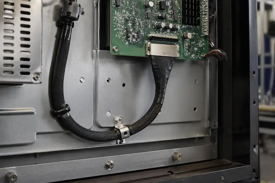
Shielded-routing LVDS harness inside an industrial display control system
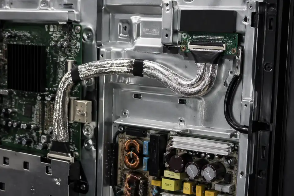
Shielded-routing LVDS harness inside a high-interference display device
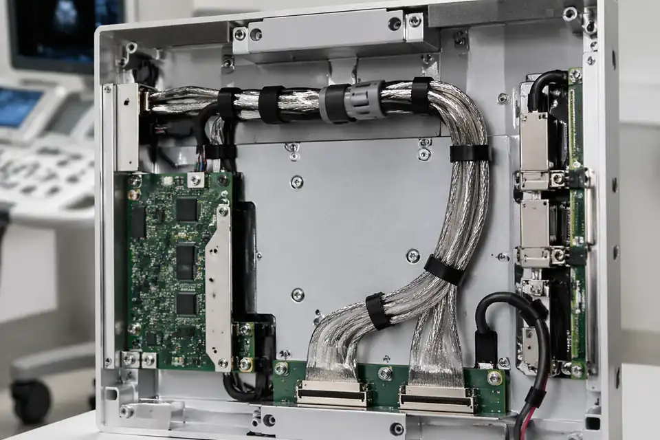
Shielded-routing LVDS harness inside a medical display interconnect module
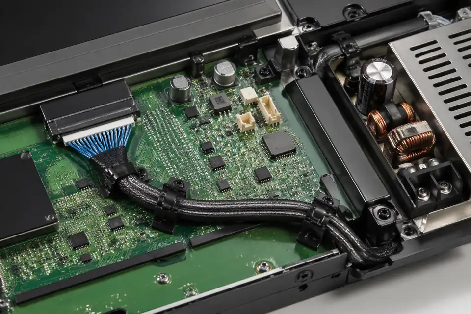
Shielded-routing LVDS harness inside a compact embedded display module near interference sources
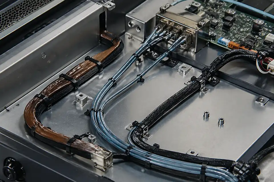
Shielded-routing LVDS upgrade-project hardware comparison context
Engineer Shielding as Part of the Current-return Path
Shield selection only makes sense with the enclosure, aggressor locations, pair construction, and grounding architecture defined. Foil, braid, drains, and connector shells are not interchangeable labels.
| NO | Shielding decision | Project input | Drawing or BOM output |
|---|---|---|---|
| 01 | Noise environment | Switching supplies, motors, radios, and external ports | Aggressor map tied to cable route |
| 02 | Differential construction | Pair count, conductor size, lay, and impedance target | Controlled wire specification and grouping |
| 03 | Overall shield | Required coverage, flexibility, thickness, and handling | Named foil or braid material |
| 04 | Drain implementation | Current path and assembly-access constraints | Drain size, position, and termination method |
| 05 | Endpoint bonding | Circuit ground, chassis ground, and shell strategy | Explicit termination at each end |
| 06 | Route separation | Minimum spacing from documented noise sources | Keep-out dimensions in installation data |
| 07 | Connector transition | Selected shells, clamps, and tail geometry | Drawing states the maximum unshielded length at each connector transition |
First-Party Engineering References
- JAE FI-X series product page
Manufacturer description of FI-X shielded variants and ground features; only the selected FI-X parts inherit those details.
Shield-path Failure Review
A shield can underperform through an undefined termination or can create an unintended current path, making system-level grounding review as important as cable coverage.
| NO | Failure pattern | Physical mechanism | Engineering control |
|---|---|---|---|
| 01 | Noise persists after shielding | Long exposed tails bypass the intended enclosure | Control transition length and connector placement |
| 02 | Mode-dependent display upset | Return path changes with chassis assembly state | Test the final bonds and covers |
| 03 | Shield discontinuity | Drain, foil, or shell connection is damaged | Inspect and electrically verify defined bonds |
| 04 | Cable becomes too stiff | Shield construction conflicts with required bend geometry | Prototype the real route before release |
| 05 | Ground-related interference | Both endpoints were bonded without system analysis | Follow the equipment grounding decision |
Verify the Shield in Its Installed State
Shielding validation should compare controlled configurations in the actual enclosure and retain the termination construction, instrument setup, operating mode, and pass limits.
| NO | Verification | Configuration | Acceptance evidence |
|---|---|---|---|
| 01 | Shield construction audit | Inspect material, overlap, drains, clamps, and shells | First article matches controlled BOM |
| 02 | Bond continuity | Measure designated endpoints using the instrument settings in the grounding test plan | Measured resistance meets the numeric limit for each named point pair |
| 03 | Route inspection | Install beside all intended aggressors and structure | Separation and crossings match CAD |
| 04 | Functional stress | Operate worst display mode with nearby loads active | No image instability or logged interface fault |
| 05 | Equipment EMC | Test the final enclosure, cables, power, and peripherals | Acceptance criteria in the product compliance plan are met |
| 06 | Post-test teardown | Examine shields and transitions after mechanical exposure | No crack, migration, or broken bond |
Engineering Capability
Engineering value in a shielded LVDS page comes from tying shield coverage, connector-shell or drain termination, grounding, route fit, and the system EMC test boundary together before release. Cross-family engineering review, drawing control, and documentation practice are covered in the Related Capability Pages below.
Engineering Capability
Review shield coverage, grounding or drain treatment, connector termination, route path, and local fit as one engineering problem.
Treat fixing points, turn zones, nearby noise sources, and the agreed system-level EMC test conditions as part of the same release definition.
Quality and Verification Highlights
Focus on repeatable route execution and stable shielding behaviour.
Watch connector tails, turn zones, and wrapped sections closely in installed builds.
Evidence Chain
Sample Approval and EMI-Review Records
Use sample confirmation records and EMI-review notes to show whether the approved sample actually matches the route, shielding, and installation conditions being quoted.
Shield and Grounding Release Records
A shielded LVDS route is controlled as a complete return-path structure, so the released record must identify shield construction, grounding points, connector transitions, nearby noise sources, and the agreed validation scope.
Shield termination drawing
Define foil, braid, drain, conductive wrap, chassis bond, or connector-shell termination details only where they apply to the approved cable structure.
Electrical and system review basis
Keep continuity, shield-connectivity, and any agreed signal-integrity or EMC result tied to the route, fixture, endpoints, and acceptance conditions used for the sample.
Grounding-revision identification
Treat changes to drain routing, shield coverage, termination points, connector shells, and chassis contact as controlled revisions rather than informal substitutions.
Termination-area protection
Support shield transitions and connector exits during packing so transport does not disturb the released grounding structure or bend the cable at a sensitive termination.
Certifications / Records Visuals
IMAGES · 04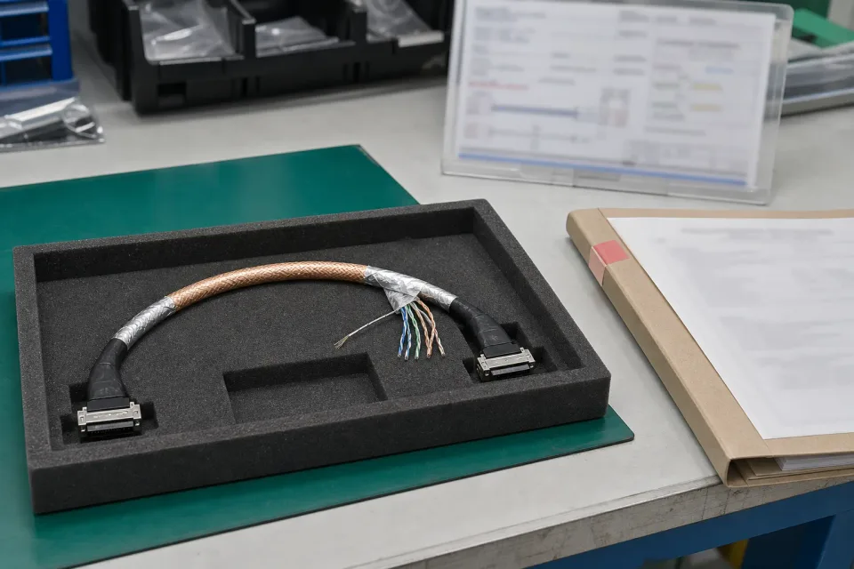
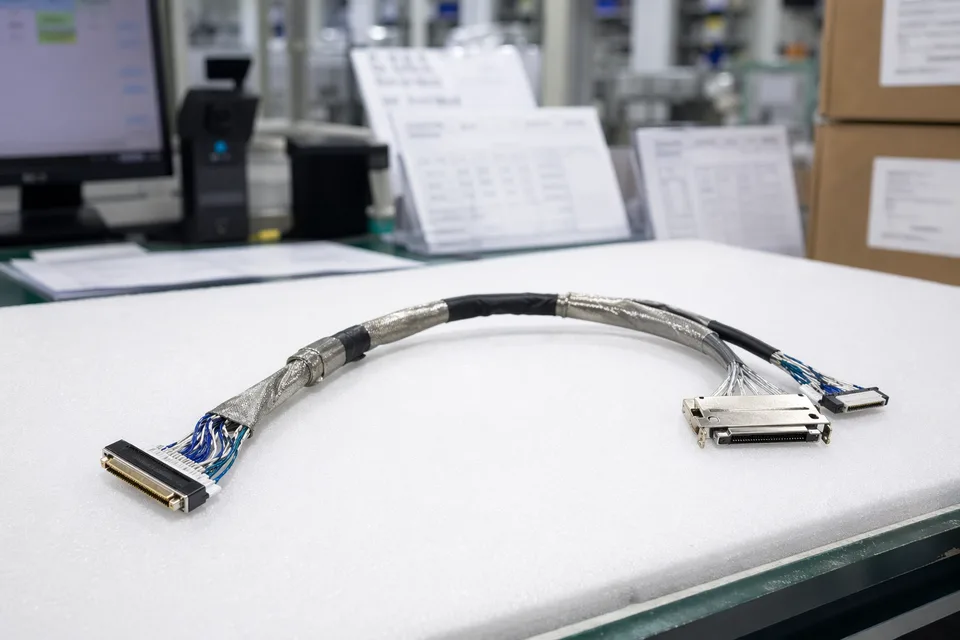
Shielded LVDS sample-approval bench showing foil and braid construction, differential pairs, drain termination, and routing reference
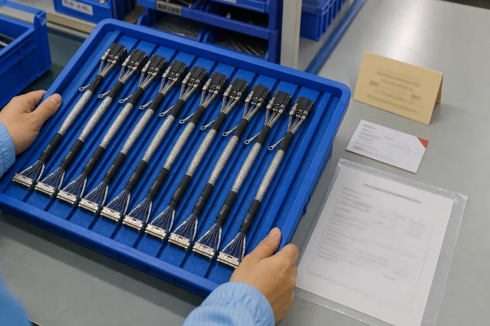
Lot tray of shielded LVDS harnesses with consistent shield treatment, revision identification, and grounding-check records
LVDS batch traceability archive with connector lot cards and harness sample visible
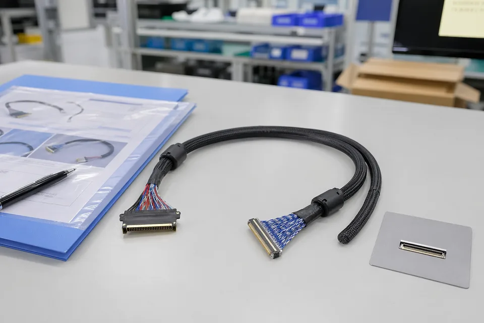
LVDS sample approval folder beside shielded cable assembly and panel connector mockup
FAQ
Can you review a shielded LVDS project from an old sample?
Yes. Old samples help, but the current route path, shielding logic, and platform revision still need to be checked before the sample can represent the released build.
What is the minimum input for a shielded LVDS quotation?
Send connector references, pin mapping, route context, shielding notes, project stage, and expected quantity.
Why do shielded LVDS projects need more than the connector reference?
Because shielding, route fit, and installation space often decide whether the harness can actually be released cleanly.
Can one shielded LVDS harness serve several display versions?
Sometimes, but only if connector fit, route geometry, shielding behaviour, and revision boundaries stay inside the same approved definition.
Can review start before the full drawing package is complete?
Yes. The grounding topology, aggressor map, proposed shield construction, transition exposure, and enclosure route are enough to identify early shield-path risks before the final drawing is complete.