Technical Reference · MEDICAL-MONITORS
Medical Monitor Display Integration
LVDS Harness Integration for Medical Monitor Platforms
Control the controller-to-panel chain, shield path, installed route, and platform revision before harness release
This page covers system integration of an internal LVDS display harness within a medical monitor platform. It does not replace the product page for a specific harness and does not claim medical-device certification for the cable. Release starts from the named controller, panel, connector and enclosure revisions, then ties the net map, shield and ground path, protected route, service access, change control, and complete-device validation to that exact configuration.
Quick Links
QUICK ACCESSStart with the sections closest to the project structure, interface requirements, and validation scope.
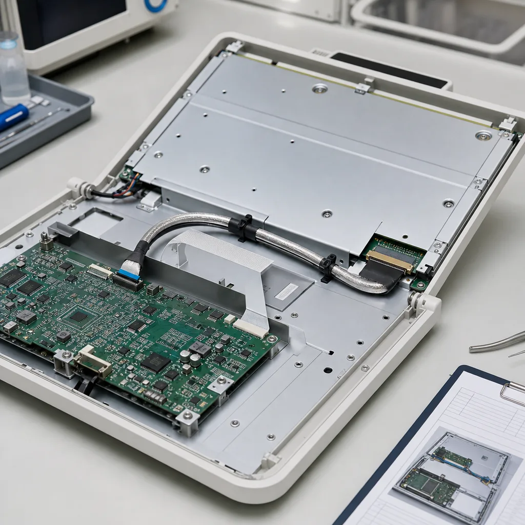
Medical Monitor LVDS Integration Boundary
Use this route when the engineering question is how an LVDS harness fits and remains controlled inside a named monitor platform. Use the product detail when the need is a specific shielded harness configuration, and use the medical cable family for patient-connected or external device cable sets.
| NO | Item | Typical Range or Meaning |
|---|---|---|
| 01 | Integration Scope | Internal controller-to-panel LVDS path within a named medical monitor or diagnostic-display platform |
| 02 | Not Covered | Patient-connected leads, external device cables, complete-device certification, or a universal replacement cable |
| 03 | Configuration Inputs | Controller, panel and enclosure revisions; both connector codes; net map; shield and chassis connections; service route |
| 04 | Engineering Decision | Pair and power allocation, shield return path, bend and fixing zones, aggressor proximity, service access, and change impact |
| 05 | Validation Boundary | Harness continuity and workmanship plus the monitor manufacturer's complete-device electrical, EMC, thermal, and functional validation |
Separate Harness Controls from Device-Level Claims
The harness supplier can control the released materials, workmanship, pin map, shield construction, dimensions, inspection and batch identity. The medical-monitor manufacturer remains responsible for determining the device classification and proving electrical safety, EMC, thermal behaviour, display performance and other complete-device requirements in the installed configuration.
| NO | Control layer | Harness release evidence | System-owner evidence |
|---|---|---|---|
| 01 | Electrical map | Released from-to table, continuity program and result | Controller-panel operation in the named hardware and firmware configuration |
| 02 | Shield and ground path | Shield coverage, drain treatment and termination shown on the harness drawing | Installed chassis connection and complete-device EMC validation |
| 03 | Mechanical route | Finished dimensions, exits, restraints and workmanship against the drawing | Fit, service access, clearance, thermal and motion checks in the released enclosure |
| 04 | Regulatory scope | Material or process documents agreed for the harness | Applicable medical-device standards, risk management and certification for the complete monitor |
| 05 | Revision release | Harness revision, approved sample, inspection and batch records | Impact assessment and revalidation decision for controller, panel, enclosure or firmware changes |
Define the Controller-to-Panel Configuration
Do not release a medical-monitor LVDS harness from a connector photo or legacy sample alone. The review package must identify the active endpoint and enclosure versions and show how the link is installed, grounded, serviced and validated.
Make Service Replacement a Controlled Change
A legacy harness that powers a display is not automatically an approved replacement. Medical-monitor service programs need a documented comparison of the old and current endpoint chain, followed by a proportionate revalidation decision from the system owner.
| NO | Change | Integration risk | Review before release |
|---|---|---|---|
| 01 | Panel or controller revision | Pin population, power, timing or connector suffix may differ | Reconcile endpoint documents and repeat the electrical and operational checks affected |
| 02 | Shield or ground change | Installed return path and EMC behaviour may change | Review termination, chassis connection, route and device-level EMC scope |
| 03 | Length or route change | Pair geometry, connector loading, aggressor exposure or service access may change | Recheck datums, bends, restraints, clearance, fit and affected device tests |
| 04 | Material substitution | Electrical, flammability, environmental or process evidence may no longer apply | Approve the BOM change and its validation boundary before production |
| 05 | Legacy sample only | Wear, undocumented repair or obsolete configuration can be copied into the new build | Derive a controlled drawing, confirm current device revisions, then approve a production-intent sample |
Integration and Change-Control Evidence
IMAGES · 05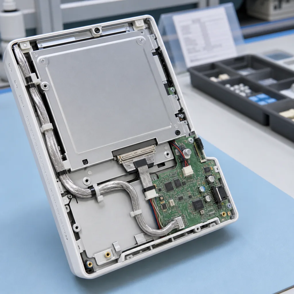
Diagnostic-display LVDS module line-art with stable display-side routing, connector fit, and shield exit
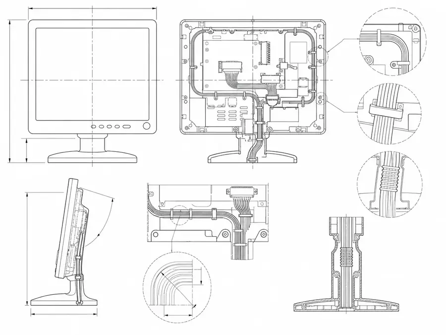
Bedside medical-screen LVDS route line-art with compact internal paths, protected handling, and bend zones
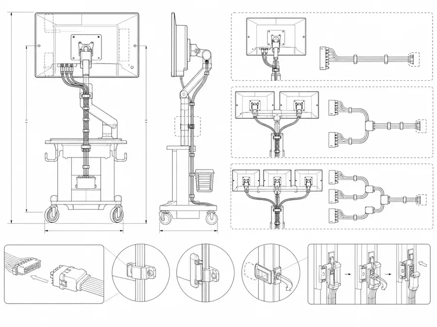
Medical-workstation LVDS layout line-art with repeatable harness release across display configurations
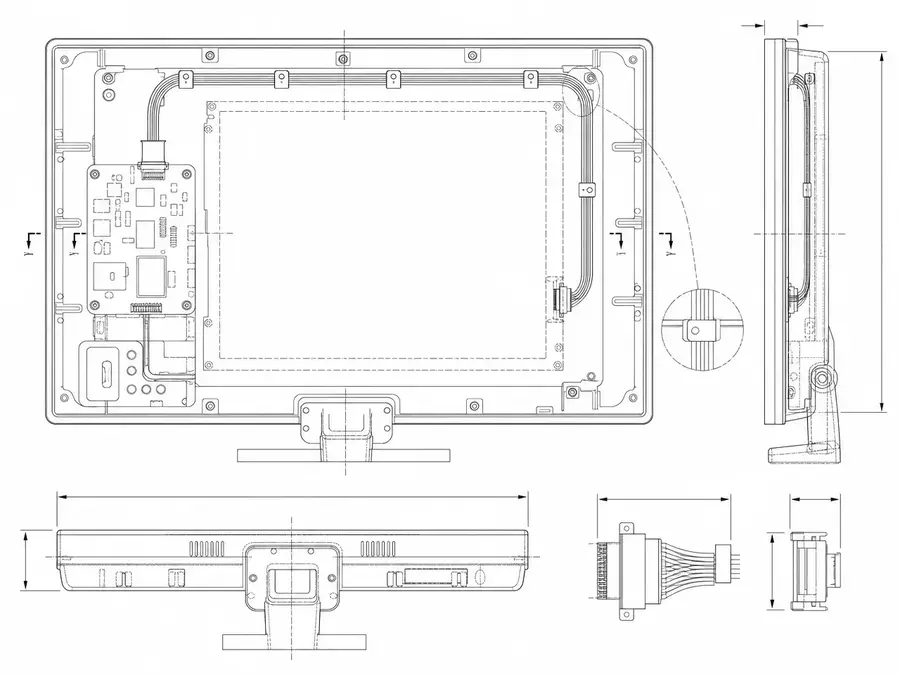
Replacement medical-monitor LVDS route line-art matching legacy paths to active service needs
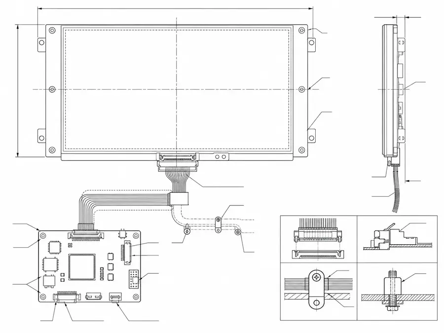
Validated display-platform LVDS layout line-art keeping cable changes under controlled records
Connect LVDS Definition to Medical Monitor Controls
The medical equipment manufacturer defines the harness through device requirements and risk controls. Connector documentation supports part selection, while IEC requirements apply at the equipment level and do not certify the harness alone.
| NO | Controlled input | LVDS design consequence | Required trace |
|---|---|---|---|
| 01 | Approved monitor variant | Fixes panel, controller, and software combination | Device configuration identifier |
| 02 | Display function requirements | Sets modes and faults that require evaluation | Requirement-to-test mapping |
| 03 | Electrical safety design | Defines applicable circuits, grounds, and separation | Reviewed system schematic reference |
| 04 | EMC risk analysis | Controls shield bonds and sensitive routing | Installed configuration drawing |
| 05 | Cleaning and disinfection | Selects compatible exposed materials and protections | Approved chemical and procedure list |
| 06 | Service process | Sets access, replacement, and misconnection safeguards | Service instruction and part label |
| 07 | Supply-chain control | Restricts connectors, wires, and process changes | Qualified BOM with notification rules |
First-Party Engineering References
- IEC 60601-1 consolidated edition listing
Primary device-level safety and essential-performance context; no standalone harness certification is implied.
- JAE FI-X series product page
Connector manufacturer data used only when a medical monitor BOM selects an exact FI-X mating set.
Medical Monitor Failure and Change Review
Each cable failure should be considered with its effect on required display information, device alarms, servicing, and configuration control rather than rated only by cable damage.
| NO | Risk scenario | Possible cause | Documented control |
|---|---|---|---|
| 01 | Required information disappears | Open pair, power fault, or connector disengagement | System fault response is verified |
| 02 | Displayed content is corrupted | Pair mapping or polarity conflicts with the panel | First article runs defined visual patterns |
| 03 | EMC behavior changes | Shield bonding or routing differs from the qualified device configuration | Assembly inspection uses configuration photographs |
| 04 | Wrong service harness fitted | Similar parts share connector appearance | Labels and service checks prevent substitution |
| 05 | Qualification becomes invalid | Material or supplier changed without assessment | Formal review precedes revised BOM release |
Medical Monitor Evidence From Lot to Device
A useful report follows the specific harness from incoming parts through first article and into the identified monitor, preserving test limits and configuration details for later review.
| NO | Evidence stage | Verification work | Traceable result |
|---|---|---|---|
| 01 | Material receipt | Match manufacturer codes and requested declarations to purchase data | Receipt record links each manufacturer lot to the required declaration and purchase-specification revision |
| 02 | Harness inspection | Check identity, dimensions, workmanship, continuity, and isolation | Report references drawing and serial or lot |
| 03 | Monitor integration | Install with qualified restraints and grounding components | Build record names every critical revision |
| 04 | Functional coverage | Exercise required display states, alarms, and recovery behavior | Results map to device requirements |
| 05 | Device EMC | Test final monitor with intended peripherals and software | Acceptance follows the device EMC plan |
| 06 | Change verification | Repeat impacted checks after approved component or process change | Assessment closes before distribution |
Engineering Capability
Engineering value in a medical-monitor LVDS page comes from tying the display-side interface to shielding and grounding, protected routing, service access, active monitor revision, and the agreed validation scope before release. Cross-family engineering review, drawing control, and documentation practice are covered in the Related Capability Pages below.
Engineering Capability
Reconcile the controller, panel and complete connector references before pin-map or mechanical release.
Review shield coverage, drain treatment, chassis connection, aggressor proximity and route fixing as one installed return path.
Dimension exits, bends, restraints, service loops and replacement access against the active enclosure revision.
Separate harness inspection from complete-device operational, EMC and regulatory validation.
Quality and Verification Highlights
Run continuity against the released map and record the tester-program revision with the result.
Inspect shield transitions, connector seating, exits, fixing and protected bends against the controlled drawing.
Tie sample approval, inspection records and batch identity to the exact monitor-platform revision.
Files and Batch Support
Medical-monitor LVDS work has its own document layer around route and fitting boundaries. Cross-family file control, batch traceability, and certification practice are summarised in the Related Capability Pages.
Medical-monitor LVDS route and fitting-boundary records
Capture the route path, local fit, and installation-space limits that are specific to the medical-monitor LVDS build so later structural differences can be traced back to the right layer of change.
Certifications / Records Visuals
IMAGES · 04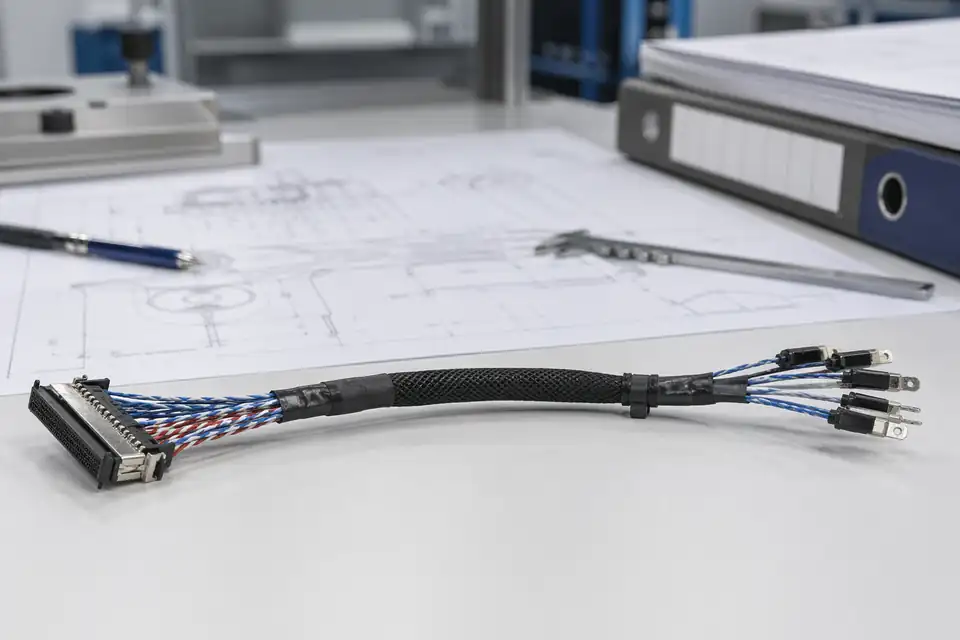
LVDS cable assembly with controlled records and identification labels
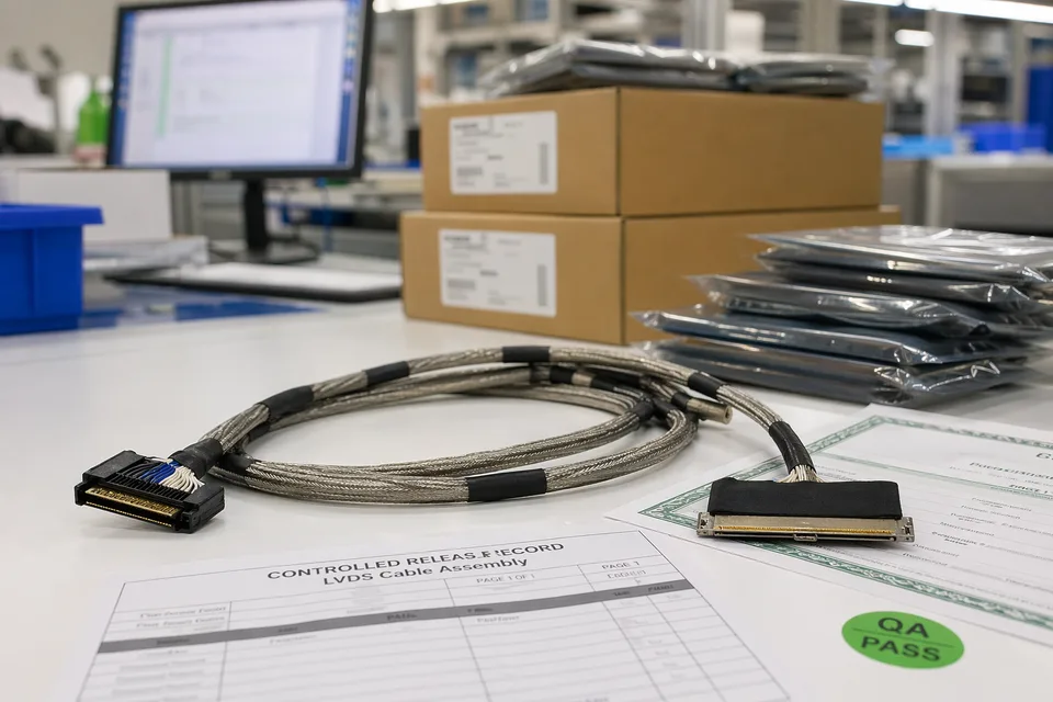
LVDS controlled release records with sample cable foreground and document sleeves
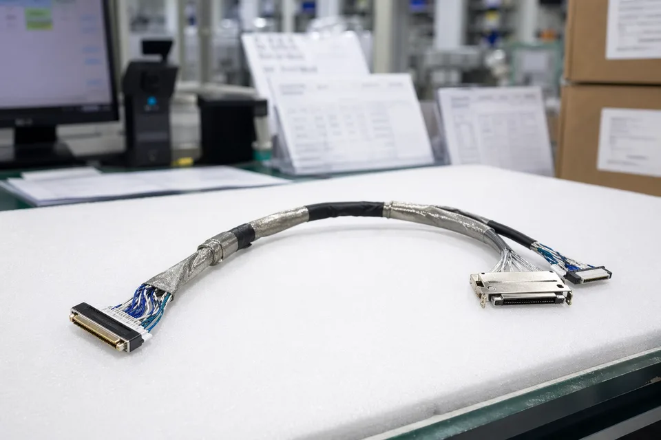
LVDS batch traceability archive with connector lot cards and harness sample visible
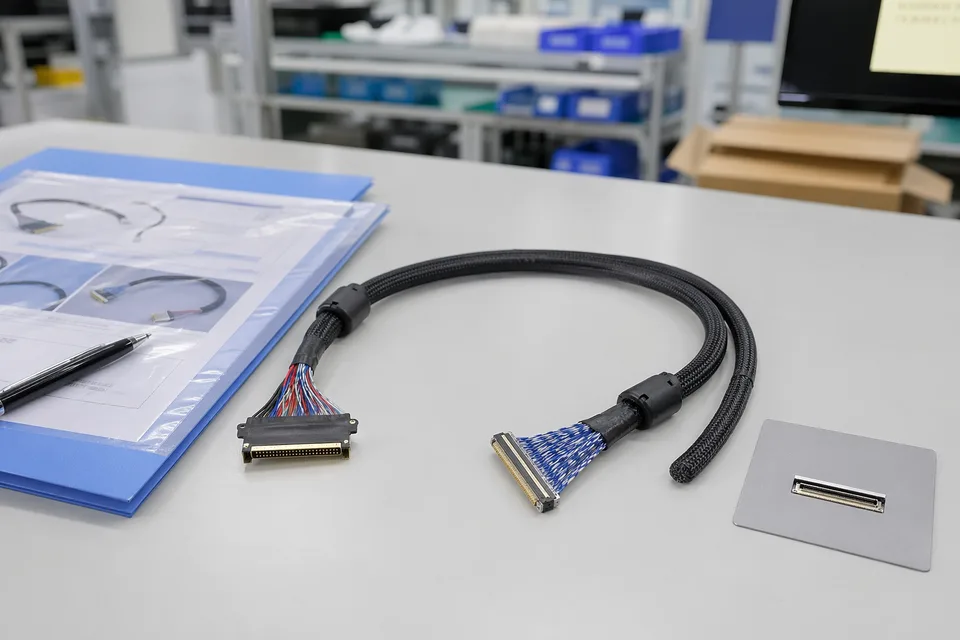
LVDS sample approval folder beside shielded cable assembly and panel connector mockup
FAQ
Is this page for all medical cable assemblies?
No. This direction is for LVDS display harnesses used in medical monitors and diagnostic display systems. Broader patient monitoring or device cable sets belong under the medical cable family.
Can you support replacement LVDS cables for medical monitors?
Yes. Replacement review should include old sample photos, connector references, pin mapping if available, and the active monitor version.
What quality records can be coordinated?
Depending on project scope, sample approval records, inspection output, batch labels, carton marks, and shipment documents can be tied to the released revision.
Why does shielding need early review?
Medical monitor routes often share compact internal spaces with other electronics, so shield coverage, drain treatment, and route fixing should be confirmed before sample release.
What should I send with an RFQ?
Connector references, pin mapping, route path, shield expectations, installed limits, project stage, expected quantity, timing, and record requirements are the most useful first inputs.