Technical Reference · 20-50-PIN
20-50 Pin LVDS Interconnects
Custom 20-50 Pin LVDS Cable Assemblies
For LVDS sourcing reviews in the supported 20-50 pin range where the complete connector and pin map still govern release
EDPcable supports custom LVDS cable assembly reviews across a project-supported 20-50 pin sourcing range. This range is a purchasing entry point, not a universal LVDS connector specification. The complete connector family and part numbers, mating direction, pin mapping, pair grouping, shielding structure, route length, and installed fit must be checked before a sample becomes the release reference.
Quick Links
QUICK ACCESSStart with the sections closest to the project structure, interface requirements, and validation scope.
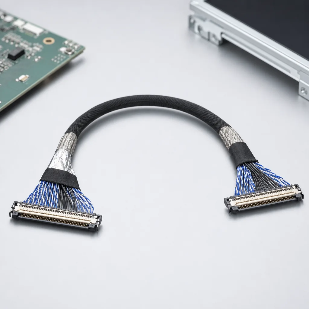
20-50 Pin LVDS Product Overview
This direction is for LVDS RFQs where 20-50 pin is a useful supported-range entry point. The released assembly still depends on complete connector confirmation, pin mapping, pair grouping, shielding execution, route length, and revision scope.
| NO | Item | Typical Range or Meaning |
|---|---|---|
| 01 | Pin-Count Range | Project-supported 20-pin, 30-pin, 40-pin, 50-pin, and adjacent configurations, subject to the selected connector family |
| 02 | Typical Devices | Embedded display modules, industrial monitors, medical monitor displays, replacement LVDS routes |
| 03 | Key Inputs | Connector references, pin mapping, route length, shield notes, active revision |
| 04 | Engineering Focus | Mating fit, differential pair handling, pin-map validity, bend and fixing zones |
| 05 | Quality Focus | Termination consistency, shield execution, continuity, released-file correspondence |
Engineering Inputs
Use these items as first-round review inputs so the discussion does not rely on the page label alone.
Send connector model numbers, mating photos, or old sample photos.
Include pin mapping, route length, and any differential-pair or shield notes.
Add enclosure limits, bend zones, fixing method, and installation context.
State whether the project is new development, replacement, validation, or repeat order.
List expected sample quantity, batch quantity, target timing, and revision boundaries.
Customer Pain Points
20-50 pin LVDS projects often sound straightforward once the product or route category is known. In real RFQ and sample work, delays usually appear in route fit, structure judgement, and revision control rather than in the label alone.
| NO | Customer Pain Point | Typical Risk | What Needs Early Confirmation |
|---|---|---|---|
| 01 | Product design issues | The connector path, structure, or local fit still does not truly match the 20-50 pin LVDS build, so the sample becomes only a temporary reference | Connector references, route path, structure boundaries, and installation space |
| 02 | Product quality issues | Execution, local fit, or batch consistency drifts across repeated 20-50 pin LVDS builds | Structure definition, quality focus, and revision linkage |
| 03 | Lead-time issues | Missing inputs force repeated sample loops and slow quotation, release, and batch timing | Connector data, route notes, project stage, quantity, and timing |
| 04 | After-sales issues | It becomes difficult to tell whether the issue came from structure, revision, or installed conditions | Drawing files, sample approval records, batch labels, and shipment records |
| 05 | Complaint-handling issues | Revision boundaries are unclear, so issue tracing stays slow | Revision confirmation, batch correspondence, and inspection records |
| 06 | Pricing issues | A broad request turns into repeated pricing changes once real fit constraints surface | Structure complexity, material expectations, quantity, and delivery boundaries |
Product Applications
This route is not only a category label. In practice, 20-50 pin LVDS work usually appears in device programs where fit, route logic, and revision scope all matter. The scenes below are the most common application contexts.
| NO | Application Scene | Scene Focus | Typical Concerns |
|---|---|---|---|
| 01 | Embedded display modules | pin-count and connector confirmation before sample release | mating direction, route length, and bend space |
| 02 | Industrial monitor programs | stable LVDS routing with clear shield and revision logic | shield termination, installed fit, and repeat orders |
| 03 | Medical monitor displays | display-side LVDS paths with controlled records | pin-map evidence, release files, and batch traceability |
| 04 | Legacy replacement routes | old sample or photo-based review | connector version, usable scope, and risk of near-match parts |
| 05 | Multi-panel platforms | one harness definition across several display options | variant boundaries, pin-map differences, and file control |
Application Scene Visuals
IMAGES · 05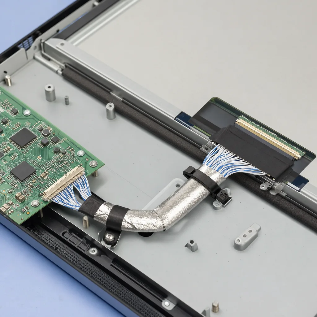
Embedded-display LVDS module line-art with pin-count and connector confirmation and a pin-map sheet
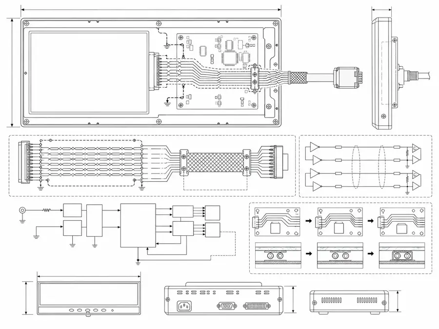
Industrial-monitor LVDS program line-art with stable routing, a clear shield, and revision logic
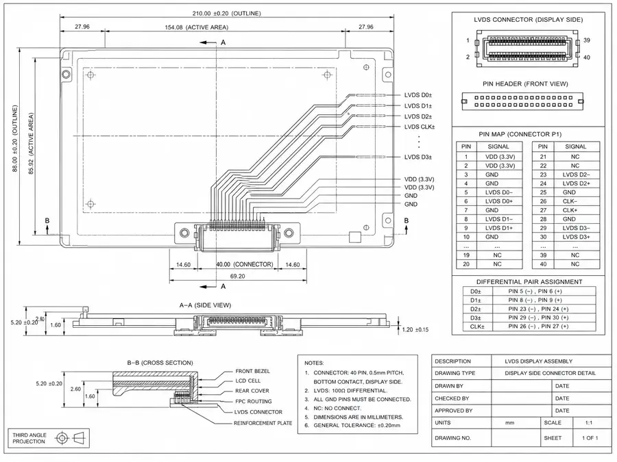
Medical-monitor LVDS display line-art with display-side paths, controlled records, and pin-map evidence
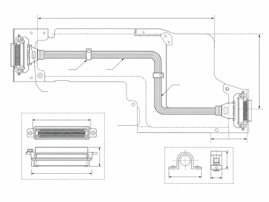
Legacy-replacement LVDS route line-art from an old sample with connector version and usable length
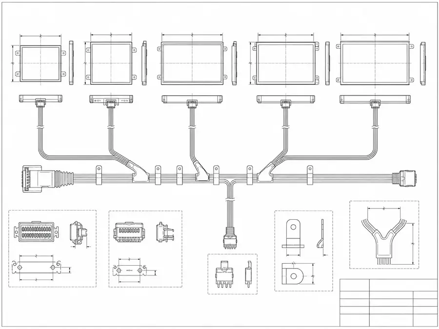
Multi-panel LVDS platform line-art with one harness definition across several display options
Convert a 20-to-50-pin Request Into a Buildable Specification
Pin count helps classify an inquiry, but 20-, 30-, 40-, and 50-position LVDS assemblies remain different designs until connector families, mappings, electrical loads, and routes are frozen.
| NO | Definition field | Input needed | Release rule |
|---|---|---|---|
| 01 | Position count | Exact contacts present and intentionally unused positions | Count agrees at both connector ends |
| 02 | Connector family | Manufacturer, series, pitch, key, and suffix | Current manufacturer drawings identify the selected components as a mating pair |
| 03 | Signal map | Panel table and source schematic for this revision | Pairs, clock, controls, and returns reconcile |
| 04 | Power allocation | Voltage, current, sequencing, and allowed drop | Conductors derive from approved system analysis |
| 05 | Cable topology | Twisted pairs, discrete wires, shields, and drains | BOM defines every construction element |
| 06 | Mechanical length | Connector datums, branches, folds, and tolerances | Dimensions correspond to installed path |
| 07 | Variant separation | Supported board and panel combination matrix | Each incompatible map gets a unique code |
First-Party Engineering References
- I-PEX CABLINE-VS product documentation
Primary example of one connector family offered in 20, 30, 40, and 50 positions; it does not define LVDS pinouts.
Pin-count Assumption Review
Most errors occur when a familiar position count is treated as a standard interface, allowing a visually plausible assembly to proceed before electrical definitions are reconciled.
| NO | Assumption failure | Consequence | Required control |
|---|---|---|---|
| 01 | Same count means same mate | Pitch or key prevents engagement | Full connector codes drive sourcing |
| 02 | Same count means same map | Signals or supplies reach incorrect contacts | Approve an endpoint-to-endpoint net list |
| 03 | Unused means unimportant | Reserved or detect contact is connected incorrectly | State treatment for every position |
| 04 | Old sample remains current | Replacement panel uses a revised assignment | Compare sample to current source documents |
| 05 | More contacts carry more current | Conductor allocation lacks a real load calculation | Use the panel's electrical budget |
Verification Gates for Any Position Count
The same release discipline applies across the range, but fixtures, mate parts, net lists, and acceptance limits must be unique to the selected contact count and platform revision.
| NO | Gate | Execution method | Release evidence |
|---|---|---|---|
| 01 | Connector identity | Verify full labels, drawings, and mating samples | Approved codes match received parts |
| 02 | Position-by-position audit | Compare tester map with both endpoint documents | Every position is mapped, reserved, or marked no-connect in both endpoint records |
| 03 | Loaded power check | Operate the panel at defined maximum demand | Drop and heating meet system limits |
| 04 | Mechanical assembly | Install with target board, panel, and enclosure | Keys, exits, and lengths fit correctly |
| 05 | Display performance | Run the platform timing and content matrix | All named timing and test-pattern cases complete with no listed image defect or interface fault |
| 06 | Variant challenge | Challenge barcode, fixture, and work-instruction controls with an intentionally incorrect near-match harness code | Incorrect options are detected and segregated |
Engineering Capability
Engineering value in a 20-50 pin LVDS review comes from moving beyond the pin count to the exact connector pair, pin map, differential-pair grouping, shield termination, and installed route. Cross-family engineering review, drawing control, and documentation practice are covered in the Related Capability Pages below.
Engineering Capability
Review the complete connector references, pin map, pair grouping, shield termination, route path, and local fit together for the 20-50 pin LVDS build.
Quality and Verification Highlights
Verify wire order and pair grouping against the released pin map, then watch connector exits and route transitions identified as critical in the installed layout.
Files and Batch Support
20-50 pin LVDS work has its own document layer around route and fitting boundaries. Cross-family file control, batch traceability, and certification practice are summarised in the Related Capability Pages.
20-50 pin LVDS route and fitting-boundary records
Capture the route path, local fit, and installation-space limits that are specific to the 20-50 pin LVDS build so later structural differences can be traced back to the right layer of change.
Certifications / Records Visuals
IMAGES · 04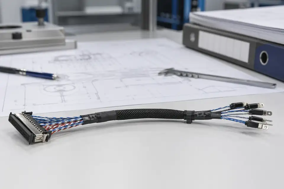
LVDS cable assembly with controlled records and identification labels
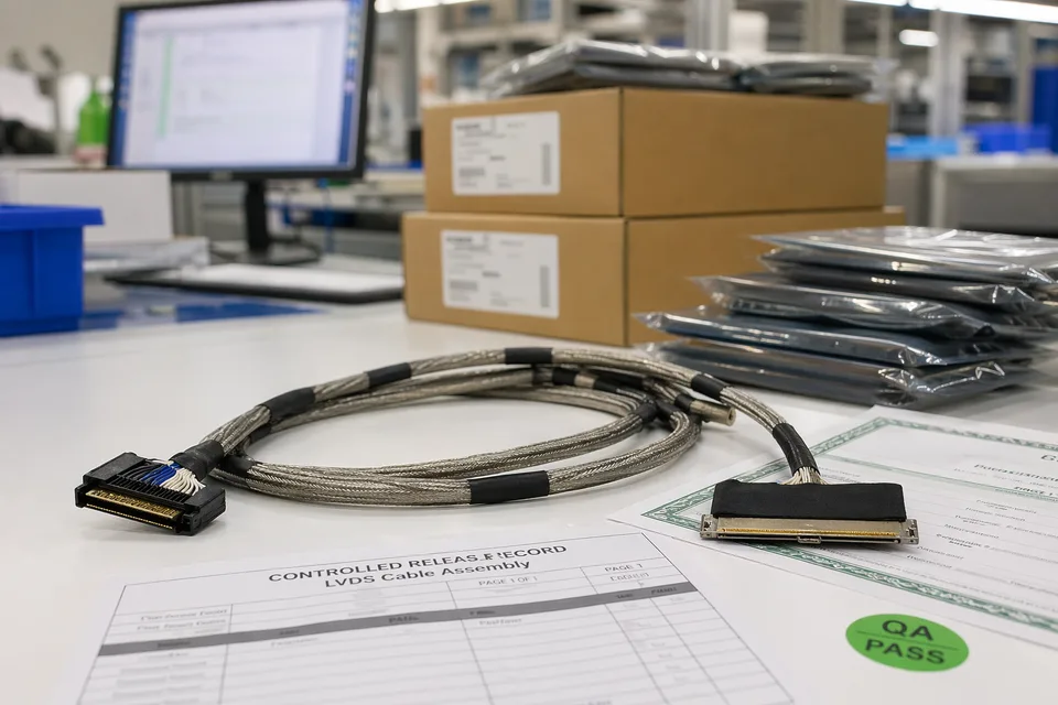
LVDS controlled release records with sample cable foreground and document sleeves
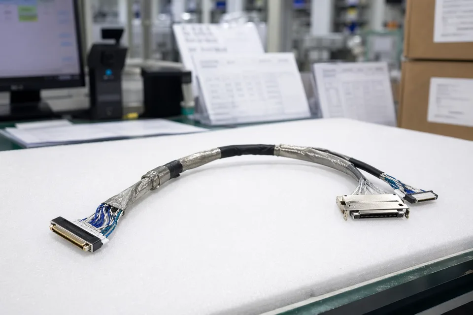
LVDS batch traceability archive with connector lot cards and harness sample visible
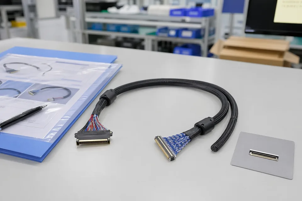
LVDS sample approval folder beside shielded cable assembly and panel connector mockup
FAQ
Can you quote from pin count alone?
Pin count is a starting point, but connector reference, pin mapping, route length, and shielding expectations are needed before a reliable quote or sample scope can be released.
Can you support 30-pin or 40-pin LVDS replacements?
Yes. Replacement review should include connector photos, old sample photos, pin mapping if available, and the device version that the replacement must fit.
Why does shielding matter on a pin-count page?
Two assemblies can share a pin count but behave differently if shield coverage, drain treatment, route length, or fixing method changes.
Can one 20-50 pin LVDS harness fit several display variants?
Sometimes, but only when connector references, pin mapping, route geometry, shield logic, and version scope stay inside one approved definition.
What should I send for the first review?
Connector references, pin mapping, route length, shield notes, installed space, project stage, expected quantity, and timing are the most useful first inputs.