Technical Reference · EMBEDDED-DISPLAY
Embedded Display LVDS
Custom LVDS Cable Assemblies for Embedded Display Systems
For embedded-display routes where connector fit, route space, and revision control matter early
EDPcable supports custom LVDS cable assemblies for embedded-display modules, panel computers, HMI units, and other systems that still depend on a stable internal-display path. The practical challenge is usually not whether the harness can be built, but whether connector matching, route geometry, local fit, and revision scope all align with the real product structure under one released definition.
Quick Links
QUICK ACCESSStart with the sections closest to the project structure, interface requirements, and validation scope.
Embedded-Display LVDS Product Overview
Embedded-display LVDS fits projects where the system context is already clear and the next review needs to judge connector fit, route geometry, local installation space, and revision scope together before sampling.
| NO | Item | Typical Range or Meaning |
|---|---|---|
| 01 | Typical Use | Embedded display modules, panel computers, HMI units, internal display retrofit work |
| 02 | Key Inputs | Connector references, pin mapping, route path, local fit notes, revision scope |
| 03 | Engineering Focus | Route geometry, local clearance, fixing method, version boundaries |
| 04 | Quality Focus | Stable termination, repeatable routing, revision-linked records |
| 05 | Release Basis | Connector path, route notes, installation limits, and file-controlled revision scope |
Customer Pain Points
Embedded-display LVDS projects often begin from a clear system category, but the real delays usually appear when the route path, local fit, and revision boundaries are still moving after the first sample has already started.
| NO | Customer Pain Point | Typical Risk | What Needs Early Confirmation |
|---|---|---|---|
| 01 | Product design issues | The connector pair and route geometry still do not truly fit the enclosure, so the sample becomes only a temporary reference | Connector references, route path, bend areas, and installation space |
| 02 | Product quality issues | Termination, route execution, or local-fit consistency drifts across batches | Structure definition, quality focus, and revision linkage |
| 03 | Lead-time issues | Missing route or fit inputs force repeated sample loops and delay release | Connector data, route path, installation notes, project stage, and quantity |
| 04 | After-sales issues | It becomes difficult to tell whether the issue came from route geometry, revision, or the enclosure itself | Drawing files, sample approval records, batch labels, and shipment records |
| 05 | Complaint-handling issues | Revision boundaries are unclear, so issue tracing stays slow | Revision confirmation, batch correspondence, and inspection records |
| 06 | Pricing issues | A broad embedded-display request turns into repeated pricing changes once real fit constraints surface | Structure complexity, material expectations, quantity, and timing |
Product Applications
Embedded-display LVDS is not only an interface path. It usually appears in systems where route length, local fit, and enclosure-space judgement all matter. The five scenes below are the most common application contexts.
| NO | Application Scene | Scene Focus | Typical Concerns |
|---|---|---|---|
| 01 | Industrial control terminals | The internal route is fixed but the enclosure remains complex | Connector matching, length split, fixing method |
| 02 | Embedded display modules | The board-to-panel distance stays more sensitive | Differential path, bend zones, installation space |
| 03 | Panel computers | Revision changes and replacement work both matter | Revision scope, sample-to-production correspondence |
| 04 | Self-service equipment display modules | Ongoing delivery and maintenance both matter | Batch consistency, records, and after-sales support |
| 05 | HMI systems | The structure stays tighter and more compact | Local route, fixing points, and release logic |
Application Scene Visuals
IMAGES · 05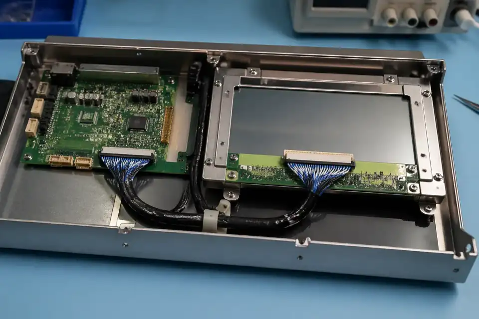
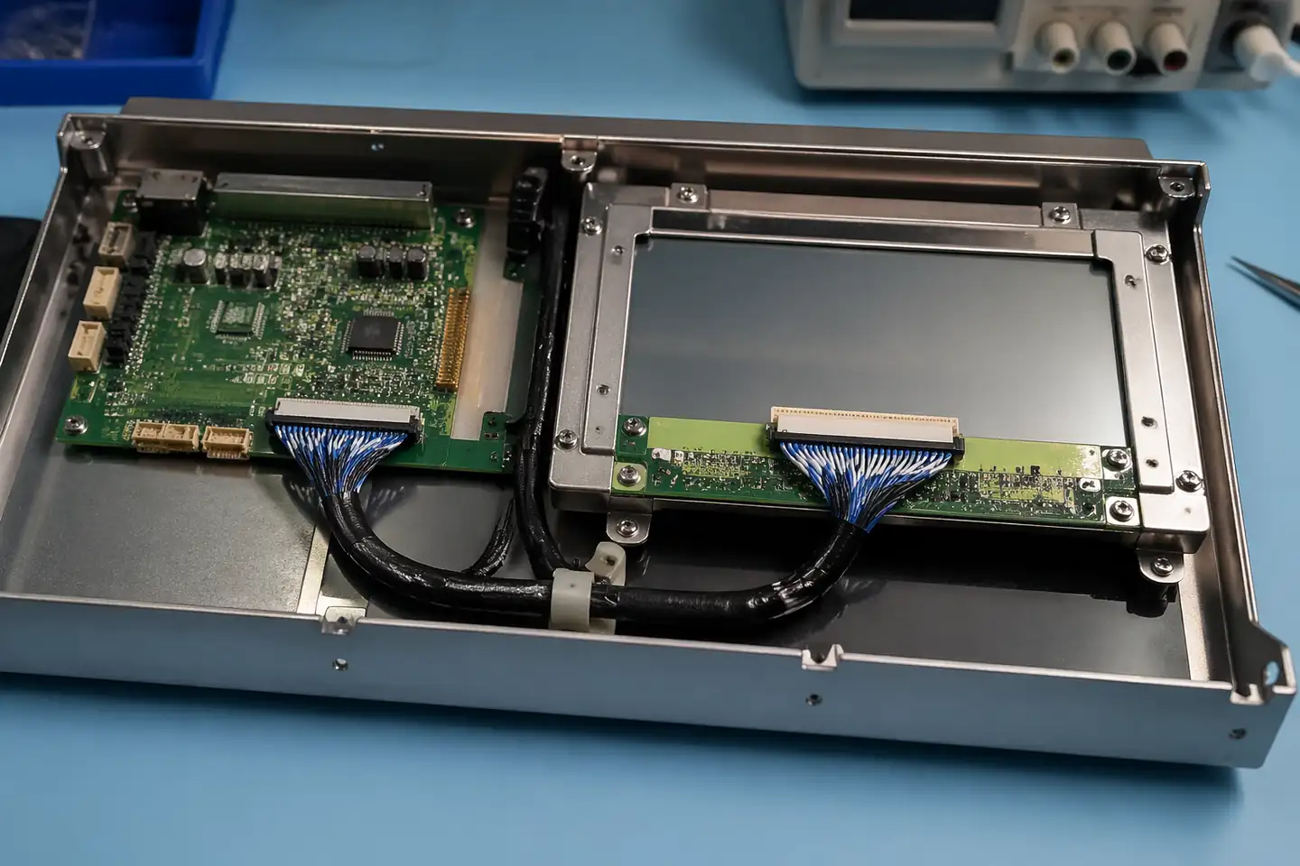
LVDS route inside an industrial control terminal display unit
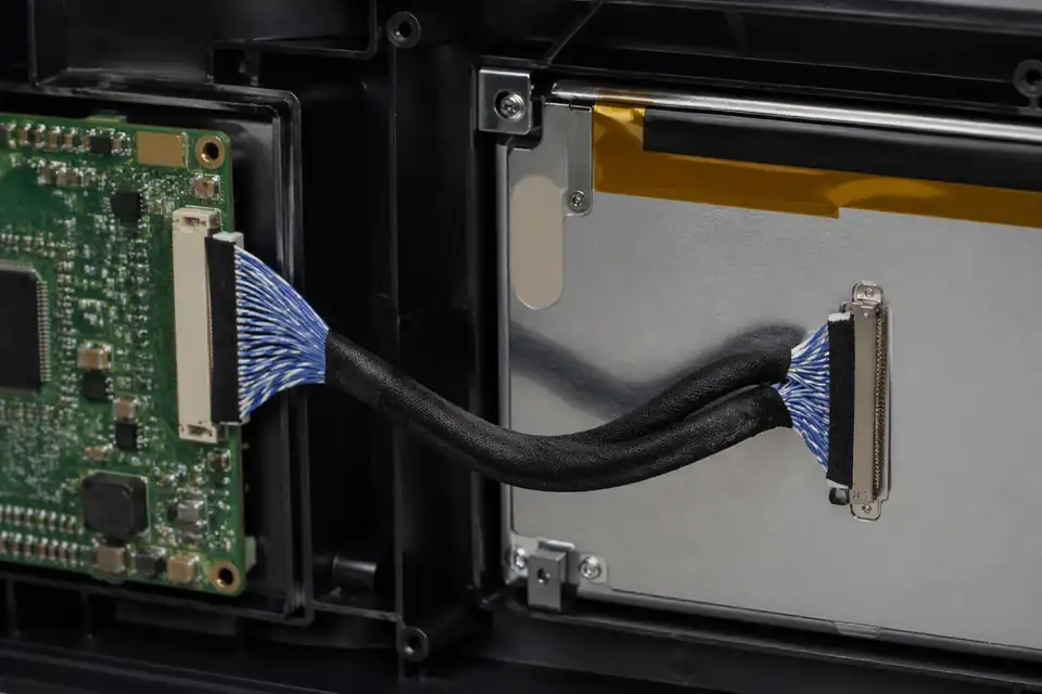
LVDS route inside an embedded display module with compact board-to-panel spacing
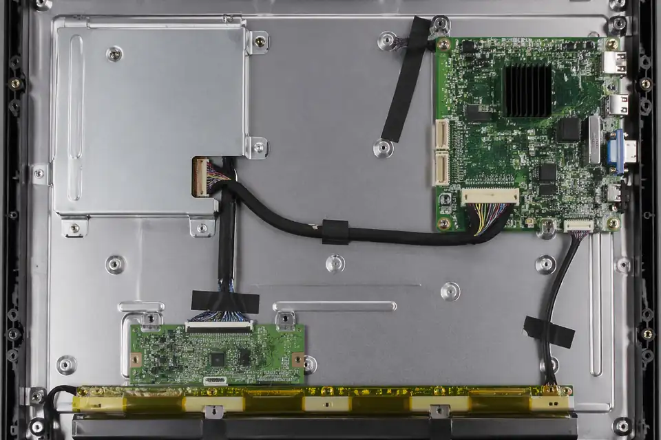
LVDS route inside a panel-PC display module with replacement-aware internal layout
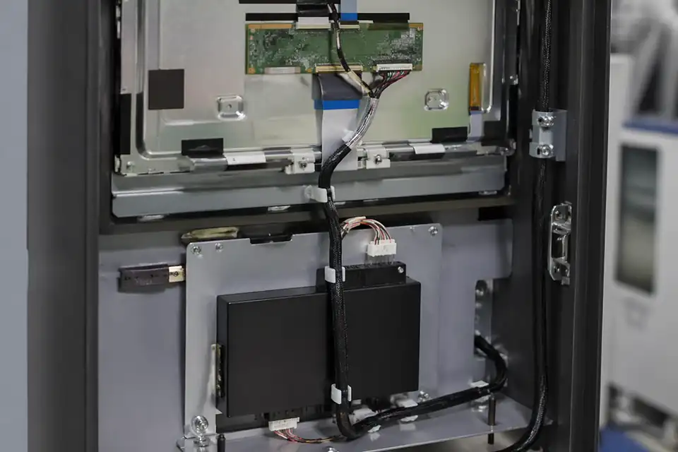
LVDS route inside a self-service display module with serviceable internal layout
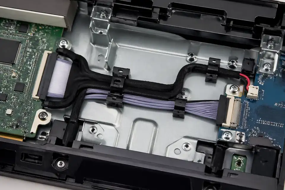
LVDS route inside a compact HMI interface system
Define LVDS Around the Embedded Product Envelope
Embedded-display programs often combine a standard panel with a custom carrier and enclosure. The harness must capture this specific combination, including service loops and installation sequence.
| NO | Definition topic | Embedded-system input | Harness output |
|---|---|---|---|
| 01 | Carrier board | Revision, connector placement, and serializer mapping | Board-end mate and net assignment |
| 02 | Display module | Full panel option and interface table | Panel-end plug and contact map |
| 03 | Enclosure geometry | Three-dimensional route, obstacles, and cover motion | Length, exits, folds, and protection |
| 04 | Power integration | Panel rails, backlight interface, and sequence | Sized conductors and separated returns |
| 05 | Signal construction | Channel format, clock, and electrical target | Specified pairs and termination layout |
| 06 | Assembly method | Technician access, order of operations, and fixtures | Workable mating and restraint features |
| 07 | Product variants | Panel and carrier combinations allowed in production | Distinct identification for incompatible builds |
First-Party Engineering References
- JAE FI-X series product page
First-party LCD connector reference for designs that specify FI-X; exact part drawings control mechanical integration.
Embedded Integration Failure Review
Integration reviews should challenge enclosure assembly, option control, and board-panel mapping because those boundaries are commonly owned by different teams.
| NO | Integration failure | Underlying mismatch | Control action |
|---|---|---|---|
| 01 | Prototype fits but production does not | Temporary routing omitted final covers or clips | Validate a production-intent mechanical build |
| 02 | Panel variant shows wrong image | Mapping mode differs across approved display options | Assign option-specific cable codes where needed |
| 03 | Cable pinched on closure | Length stack ignores cover engagement sequence | Review route during assembly simulation |
| 04 | Unexpected emissions | Carrier grounding and cable shield were designed separately | Approve one system return-path drawing |
| 05 | Service damages connector | Removal access conflicts with latch or pull direction | Demonstrate documented replacement steps |
Embedded Display Integration Gates
The harness is ready only after electrical inspection and product integration agree, including the final carrier, panel, enclosure, grounding parts, and assembly method.
| NO | Integration gate | Evaluation | Release criterion |
|---|---|---|---|
| 01 | Endpoint definition | Reconcile carrier schematic and panel connector table | No unresolved or inferred net |
| 02 | Cable inspection | Measure dimensions and test every electrical path | Drawing requirements are met |
| 03 | Assembly trial | Follow production sequence with all enclosure hardware | No forced mate, pinch, or rework |
| 04 | Functional matrix | Operate each released carrier-panel-software combination | Each test case meets its defined image, control-state, and diagnostic-log criteria |
| 05 | Environmental exposure | Run the named thermal and mechanical profiles for their specified durations | Post-test inspection and electrical checks meet the cited acceptance criteria |
| 06 | Service trial | Replace panel using approved access and tools | Correct reconnection is repeatable |
Engineering Capability
Engineering value in an embedded-display LVDS page comes from tying connector fit, route geometry, and local installation-space limits together before release. Cross-family engineering review, drawing control, and documentation practice are covered in the Related Capability Pages below.
Engineering Capability
Review route path, bend zones, and local clearance together in the real enclosure context.
Treat fixing logic and exit direction as part of the same release decision.
Quality and Verification Highlights
Focus on repeatable route execution and local-fit consistency.
Watch connector tails, bend transitions, and retention points closely in compact builds.
Evidence Chain
Sample Approval and Installed-Fit Records
For an embedded-display release, retain the carrier-panel configuration, firmware, enclosure revision, service-loop dimensions, fixing features, and closed-housing fit evidence for the approved sample.
Embedded-Display Configuration Records
Embedded-display programs need configuration records that tie the board revision, panel revision, pin map, pair grouping, auxiliary circuits, connector orientation, and constrained internal route together.
Platform-specific interface drawing
Freeze both endpoint part numbers, viewing directions, pair assignments, power or backlight conductors, shield details, and route-critical dimensions for the target platform.
Board-panel sample confirmation
Retain mapping verification and installed-fit approval for the exact board, panel, enclosure, and fixing arrangement used during sample release.
Configuration-level identification
Use a released assembly number and revision that distinguish board spins, panel alternatives, pin-map changes, and mechanical-route updates.
Install-ready packing and marking
Protect low-profile connector exits and use clear end or orientation marks where multiple embedded-display configurations could otherwise be confused at assembly.
Certifications / Records Visuals
IMAGES · 04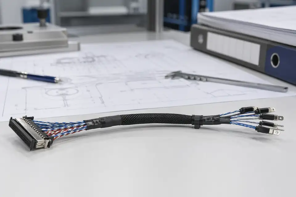
LVDS cable assembly with controlled records and identification labels
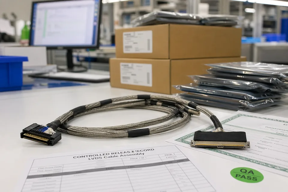
LVDS controlled release records with sample cable foreground and document sleeves
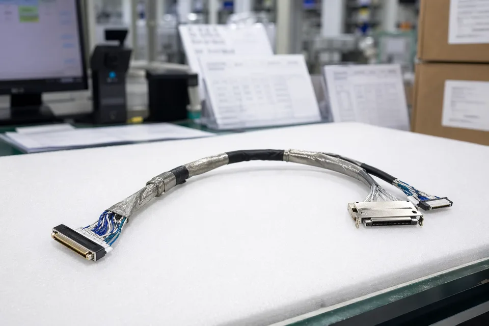
LVDS batch traceability archive with connector lot cards and harness sample visible
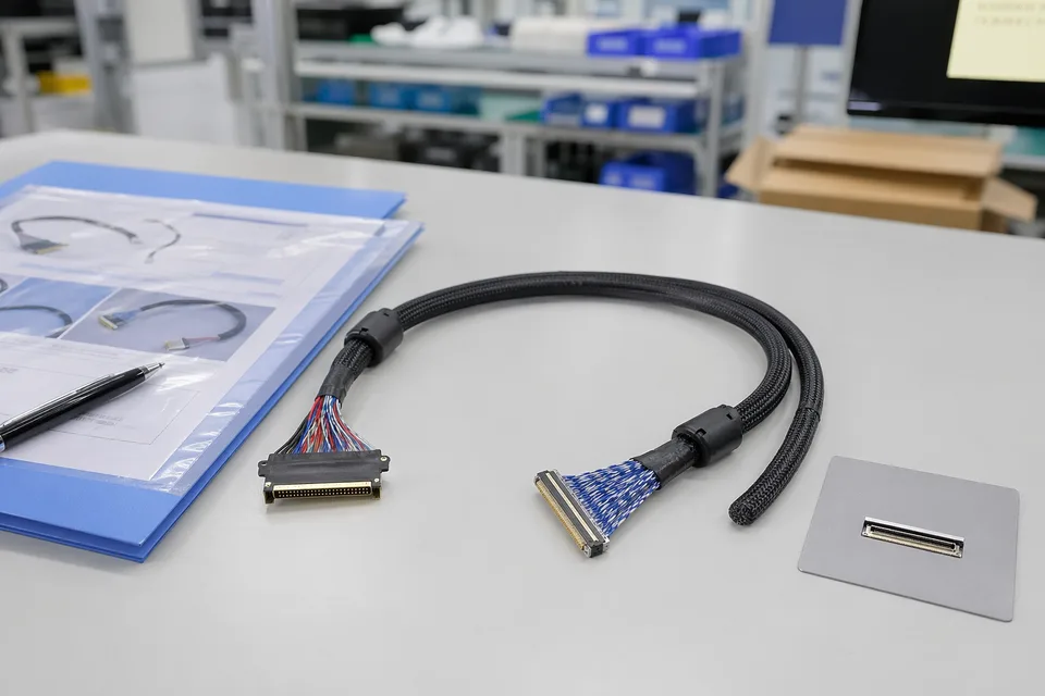
LVDS sample approval folder beside shielded cable assembly and panel connector mockup
FAQ
Can you review an embedded-display project from an old sample?
Yes. Old parts help, but the current route path, local-fit conditions, and platform revision still need to be checked before the sample can represent the released build.
What is the minimum input for an embedded-display LVDS quotation?
Send connector references, pin mapping, route context, local-fit notes, project stage, and expected quantity.
Why do embedded-display LVDS builds need more than a connector reference?
Because route geometry, local clearance, and fixing logic often decide whether the harness truly fits the product.
Can one LVDS cable serve several display versions?
Sometimes, but only if connector fit, route geometry, and revision scope stay inside the same approved definition.
Can review start before the full drawing package is complete?
Yes. The carrier and panel references, enclosure CAD, preliminary pin table, grounding parts, and installation sequence support an integration review before every production dimension is frozen.