Technical Reference · BOARD-TO-PANEL
Board-to-Panel LVDS Interconnect
LVDS Harnesses Defined from Controller Board to Panel
Reconcile both endpoints, every signal and power contact, and the production-intent installed route
This page covers a complete controller-board-to-panel LVDS chain, not a generic cable style. EDPcable releases the harness against one board revision, one panel option, both connector ordering codes, endpoint contact views, differential-pair grouping, power and control mapping, route datums, restraint, and device configuration.
Quick Links
QUICK ACCESSStart with the sections closest to the project structure, interface requirements, and validation scope.
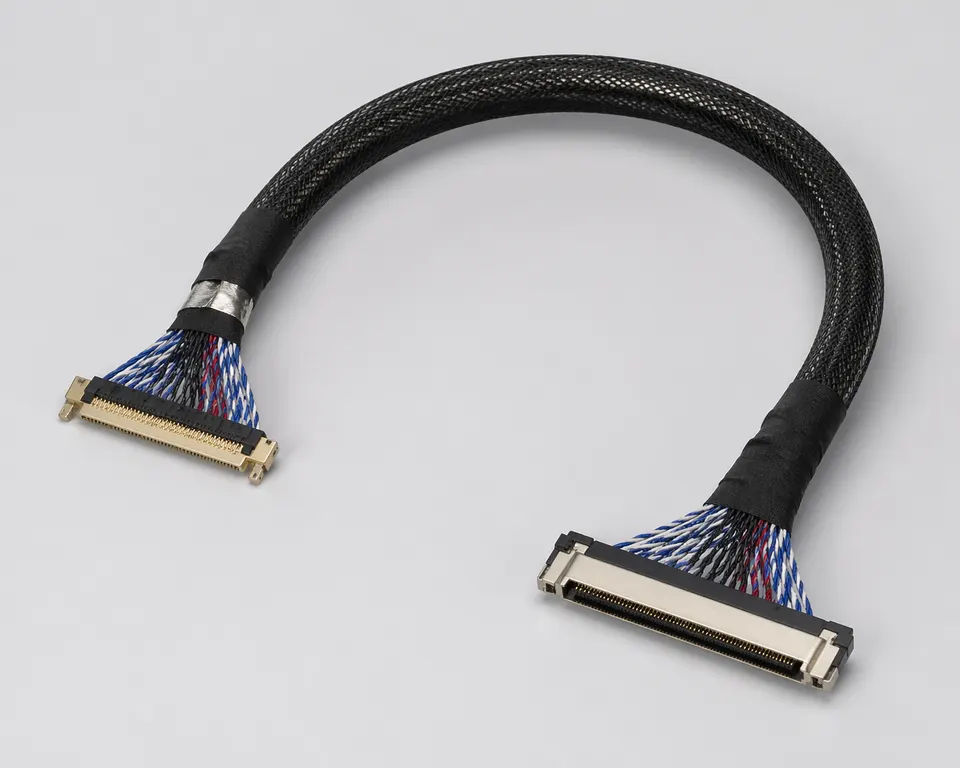
Endpoint-to-Endpoint Release Inputs
Use this path after the interface is confirmed as LVDS. The RFQ must independently identify the controller and panel endpoints, then reconcile their mating parts, contact views, channel map, power allocation, and installed geometry.
| NO | Release field | Project definition |
|---|---|---|
| 01 | Typical Use | A named controller board revision connected to a named panel or TCON option |
| 02 | Key Inputs | Complete endpoint part numbers, contact views, pair identities and polarity, power, controls, grounds, and reserved contacts |
| 03 | Engineering Focus | Route datums, connector exits, pair grouping, bend zones, retention, service motion, and enclosure clearance |
| 04 | Quality Focus | Netlist test, loaded supply-path checks where required, workmanship, installed fit, image operation, and configuration trace |
| 05 | Release Basis | Approved schematics and panel data, controlled drawing, production-intent sample, and named device test setup |
Engineering Inputs
Use these items as first-round review inputs so the discussion does not rely on the page label alone.
Provide board schematic and revision, exact panel option data, both connector codes, and unambiguous contact views.
Provide pair identities and polarity, power and controls, grounds, reserved contacts, and the released net map.
Provide datum-to-datum lengths, exits, bends, clips, service motion, fixing, strain relief, and enclosure clearance.
State sample, pilot, and production quantities, target dates, and the supported board-panel combination matrix.
Define netlist, supply-path, installed-fit, image-operation, and any SI or EMC test method and limits.
Customer Pain Points
Board-to-panel LVDS projects often begin from a clear schematic view, but delays usually appear once the cable has to live inside the actual enclosure. The six problems below are the ones that most often slow the project down.
| NO | Customer Pain Point | Typical Risk | What Needs Early Confirmation |
|---|---|---|---|
| 01 | Product design issues | The connector pair and route geometry look fine on paper but still do not fit the enclosure | Board-side and panel-side references, route path, bend areas, and installation space |
| 02 | Product quality issues | Termination, path execution, or local fixing consistency drifts across batches | Structure definition, quality focus, and revision linkage |
| 03 | Lead-time issues | Missing route or fit inputs force repeated sample loops and delay release | Connector data, route length, installation notes, project stage, and quantity |
| 04 | After-sales issues | It becomes difficult to tell whether the issue came from the route, the revision, or the enclosure itself | Drawing files, sample approval records, batch labels, and shipment records |
| 05 | Complaint-handling issues | Revision boundaries are unclear, so issue tracing stays slow | Revision confirmation, batch correspondence, and inspection records |
| 06 | Pricing issues | A broad LVDS request turns into repeated pricing changes once real fit constraints surface | Structure complexity, material expectations, quantity, and timing |
Product Applications
Board-to-panel LVDS is not only an interface path. It usually appears in display programs where route length, local fit, and installation boundaries all matter. The five scenes below are the most common application contexts.
| NO | Application Scene | Scene Focus | Typical Concerns |
|---|---|---|---|
| 01 | Control-board to display-panel links | The relationship is fixed but the structure still stays sensitive | Differential path, length split, installation space |
| 02 | Internal display modules | The space is tighter and the route turns are more constrained | Board-side / panel-side fit, route stability, fixing points |
| 03 | Embedded display systems | The route has to be judged together with the enclosure | Connector matching, bend zones, revision boundaries |
| 04 | Industrial display terminals | The environment is more demanding and batch rhythm is longer | Structure protection, file correspondence, and delivery stability |
| 05 | Replacement programs | The old route may not still match the live product version | Release conditions, record traceability, and usable scope |
Application Scene Visuals
IMAGES · 05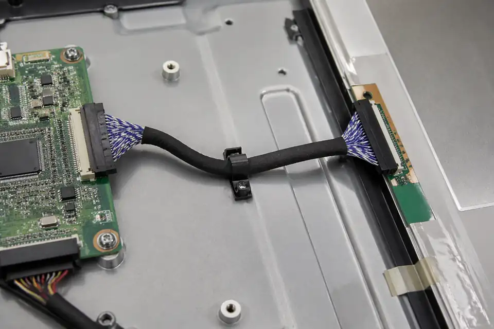
Board-to-panel LVDS route between controller board and display panel
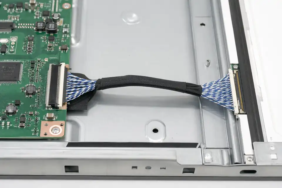
Board-to-panel LVDS connection inside a compact display module
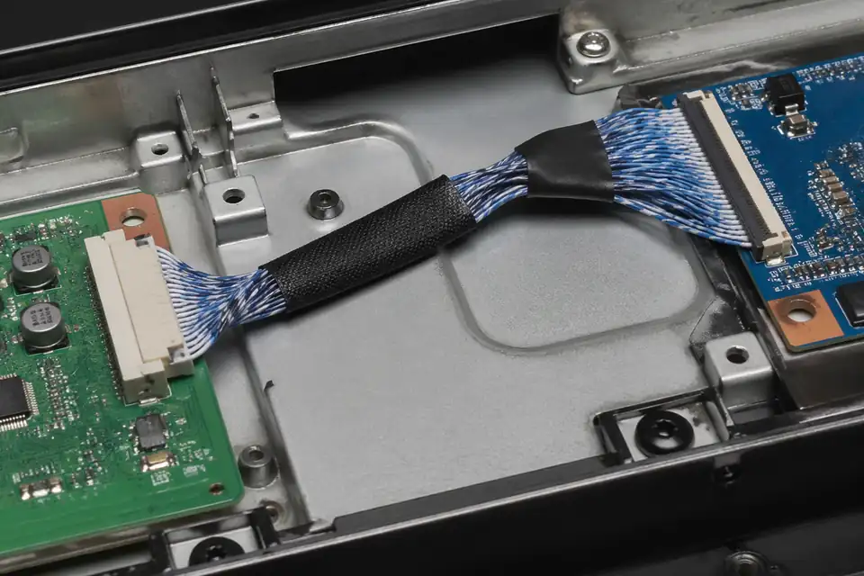
Board-to-panel LVDS route inside an embedded display system housing
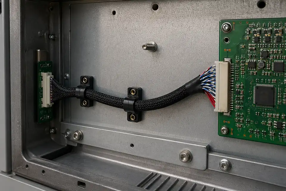
Board-to-panel LVDS route inside an industrial display terminal
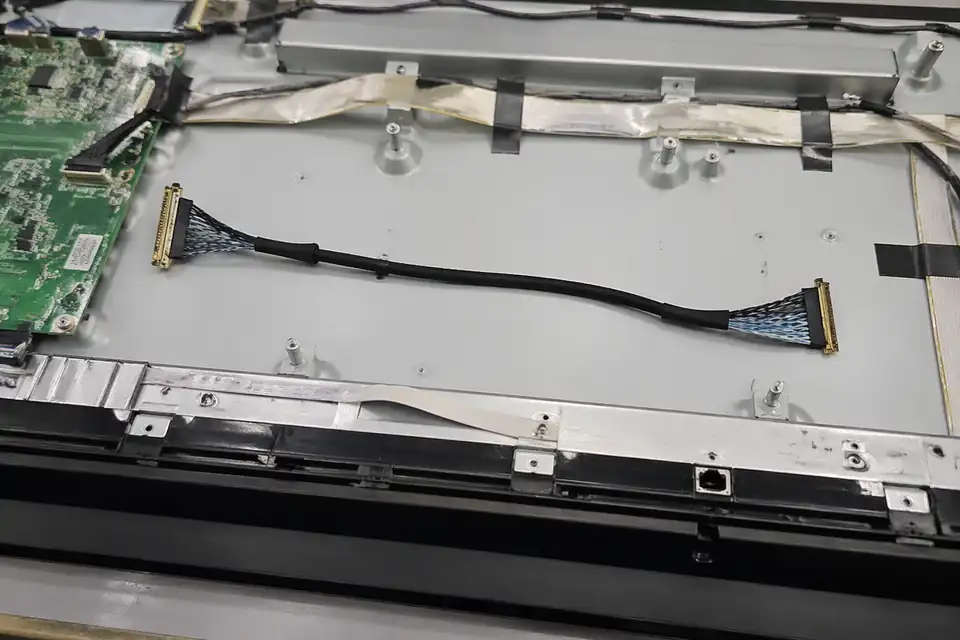
Board-to-panel LVDS replacement-project hardware comparison context
Define the Actual LVDS Board-to-panel Chain
A board-to-panel assembly must be released against one transmitter board, one panel or TCON option, their exact connectors, and the installed route. The label LVDS does not determine pin order or power distribution.
| NO | Interface decision | Required source | Released definition |
|---|---|---|---|
| 01 | Controller endpoint | Board revision, schematic, and connector BOM | Pin-one datum and source net names |
| 02 | Panel endpoint | Exact panel datasheet and option code | Mating part and panel-side assignment |
| 03 | Differential channels | Serializer format, mapping mode, and clock topology | Pair identities, polarity, and grouping |
| 04 | Power and control | Rail, backlight, enable, and return requirements | Conductor allocation from approved calculations |
| 05 | Connector set | Complete board-side and panel-side ordering codes | Compatible mates named on the drawing |
| 06 | Installed length | Board and panel datums along the real route | Finished dimensions with stated tolerances |
| 07 | Mechanical support | Clips, bends, edge crossings, and service motion | Strain relief and protected routing zones |
First-Party Engineering References
- JAE FI-X series product page
First-party example of an LCD board-to-cable connector family; applicability requires exact FI-X part selection.
Board-to-panel Definition Failures
Endpoint errors can damage hardware or create misleading intermittent symptoms, so review begins with independent board and panel evidence rather than an old harness alone.
| NO | Failure mode | Likely definition error | Preventive evidence |
|---|---|---|---|
| 01 | No image at power-up | Board and panel maps use different contact views | Net list includes connector datum views |
| 02 | Corrupted colors or columns | Channel mapping or pair polarity is incorrect | Serializer mode matches panel requirements |
| 03 | Panel electrical damage | Power contact allocation or rail value was assumed | Released schematic controls every supply net |
| 04 | Connector cannot seat | Series, key, pitch, or orientation differs | Both complete mating codes are approved |
| 05 | Intermittence after assembly | Route leaves axial or side load at a tail | Installed sample shows neutral connector exits |
Board-to-panel Release Evidence
The test unit should preserve the same board, panel, firmware, grounding, and physical installation that the report identifies, otherwise a passing result has limited reuse.
| NO | Verification step | Method | Acceptance artifact |
|---|---|---|---|
| 01 | Document reconciliation | Compare board schematic, panel table, BOM, and cable print | Every contact has one approved function |
| 02 | Harness net test | Measure continuity and isolation against released mapping | Serialized tester output |
| 03 | Supply path | Measure loaded voltage and temperature at defined conditions | Loaded voltage, voltage drop, and conductor temperature meet the numeric limits in the released specification |
| 04 | Installed fit | Build into production-intent board and panel mounts | No interference or connector preload |
| 05 | Image operation | Exercise all specified panel timing and content modes | No persistent visual or link fault |
| 06 | Configuration capture | Record hardware, firmware, panel, and harness revisions | Approval identifies one reproducible build |
Engineering Capability
Engineering value comes from tying connector fit, route length, and installation-space judgement together before release. Cross-family engineering review, drawing control, and documentation practice are covered in the Related Capability Pages below.
Engineering Capability
Review board-side and panel-side matching before treating the route as sample-ready.
Treat route length, bend areas, and local fit as one structure problem.
Quality and Verification Highlights
Focus on repeatable routing and stable connector fit.
Watch turn zones, clamp points, and local-fit conditions carefully in compact enclosures.
Evidence Chain
Sample Approval and Installed-Fit Records
For a board-to-panel release, retain the approved endpoint pair, pin map, loaded supply results, cable datums, bend clearances, clamp locations, and photographs of the tested panel installation.
Board-to-Panel Interface Release Records
Board-to-panel LVDS traceability begins with the exact source and panel revisions, then holds the pin map, pair grouping, auxiliary circuits, shielding, and installed route to that interface pair.
Endpoint and pin-map drawing
List complete board and panel connector part numbers, viewing directions, pin assignments, differential-pair grouping, power, backlight, and control circuits where present.
Sample continuity and route approval
Keep mapping verification and the installed-fit result with the approved board-panel combination, route length, bend zones, and fixing points.
Board-panel revision pairing
Use released part and revision identifiers that distinguish panel variants, board spins, connector suffixes, and mapping changes across repeat orders.
Orientation-aware delivery
Protect both connector exits and preserve orientation or end labels so the assembly reaches installation without an avoidable reverse-fit risk.
Certifications / Records Visuals
IMAGES · 04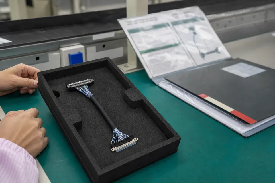
Board-to-panel LVDS sample-approval bench with board-side and panel-side connectors, pin map, and routing reference
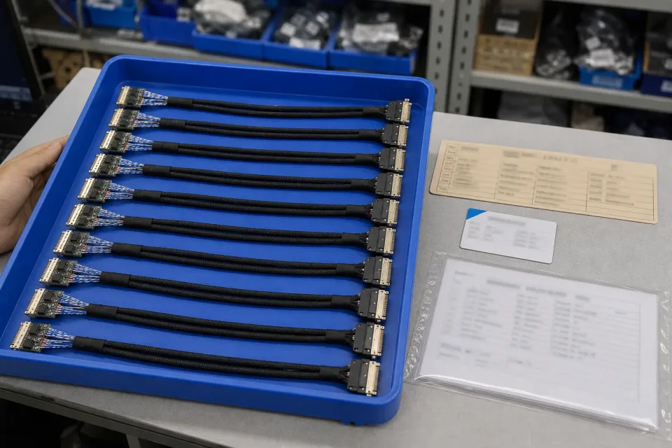
Lot tray of finished board-to-panel LVDS harnesses with revision identification and pre-shipment records
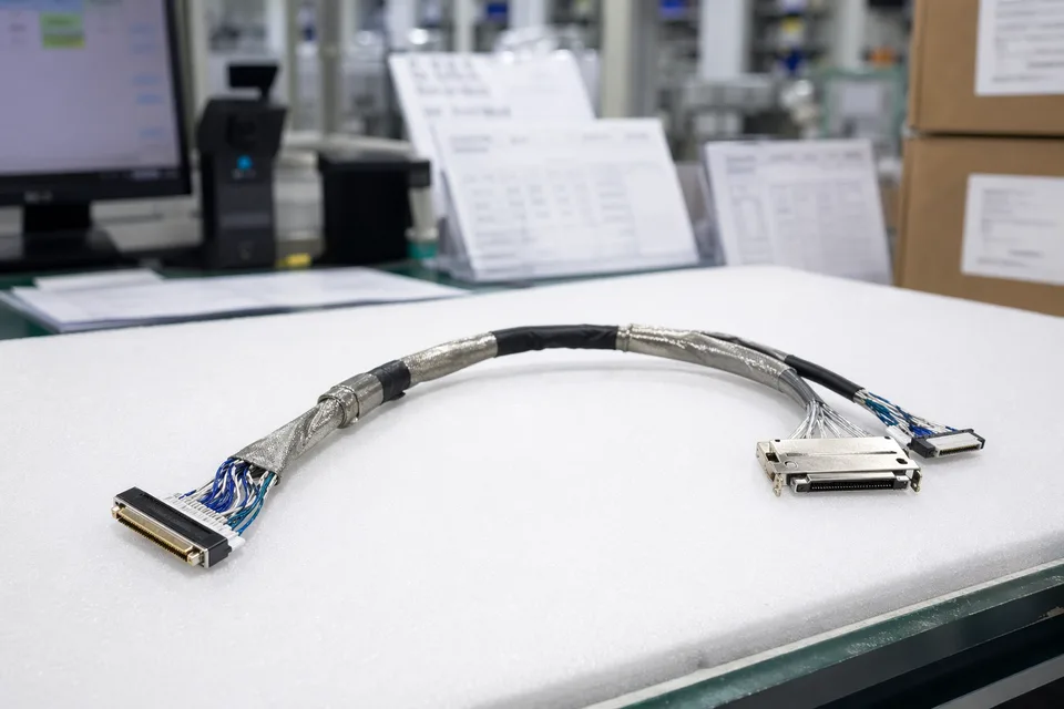
LVDS batch traceability archive with connector lot cards and harness sample visible
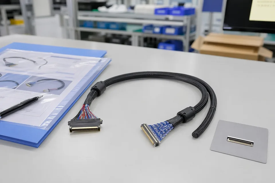
LVDS sample approval folder beside shielded cable assembly and panel connector mockup
FAQ
Can you work from an old sample or existing LVDS harness?
Yes. Old parts and legacy samples are useful starting points, but the connector pair, route length, and installation space still need to be checked against the current platform.
What is the minimum input for a board-to-panel LVDS quotation?
At minimum, send board-side and panel-side connector references, pin mapping, route length or target path, project stage, and expected quantity.
Does a matching connector pair guarantee the harness will fit?
No. Mechanical direction, local clearance, and the first turn often decide whether the assembly truly fits inside the enclosure.
Can one LVDS cable be shared across several panel versions?
Sometimes, but only if pin mapping, connector family, route geometry, and fixing points all stay within the same approved revision boundary.
Can you review the project before we finish the full drawing package?
Yes. A practical early review can start from connector photos, routing references, length targets, and structure context, then tighten once the drawing set is clearer.