Technical Reference · FOLDED-ROUTING
Folded Flexible Routing
Custom Folded-Routing FFC / FPC Assemblies
For flexible routes formed during assembly and held in one installed position
EDPcable supports statically folded FFC and FPC assemblies for fixed display paths, chassis turns, and compact internal layouts. Confirm fold lines, keep-out zones, connector exits, reinforcement, installed clearance, and assembly sequence against the approved drawing. Routes that move repeatedly with a hinge require a dynamic motion and cycle-life review and belong to the display-hinge direction.
Quick Links
QUICK ACCESSStart with the sections closest to the project structure, interface requirements, and validation scope.
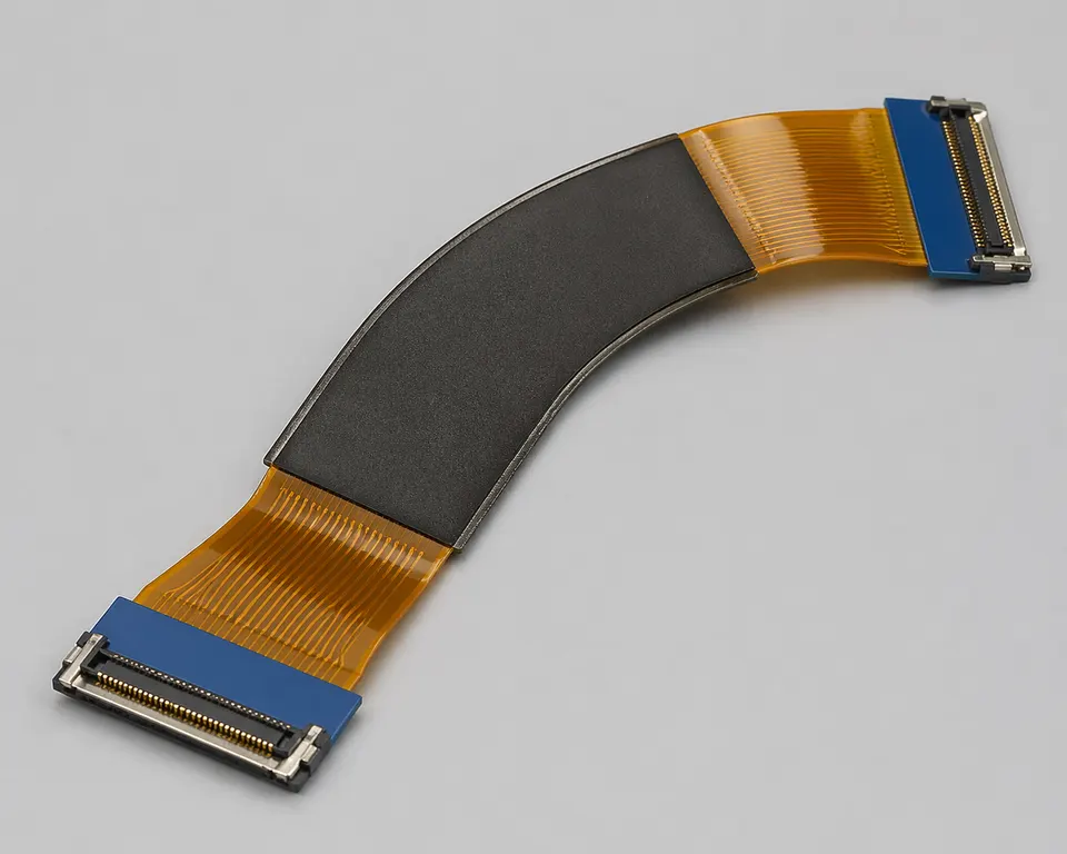
Folded-Routing Product Overview
This direction covers a cable formed during installation and then held in a defined position. Review the installed three-dimensional path, fold locations, protected areas, and post-install inspection without treating a static fit check as dynamic-flex validation.
| NO | Item | Typical Range or Meaning |
|---|---|---|
| 01 | Typical Use | Fixed display routes, formed chassis turns, folded internal links, compact-device assemblies |
| 02 | Key Inputs | Route path, bend zones, reinforcement notes, local-fit limits, revision scope |
| 03 | Engineering Focus | Fold-line location, first turn, reinforcement positions, installed clearance |
| 04 | Quality Focus | Installed-shape consistency, surface condition after forming, revision-linked records |
| 05 | Release Basis | Route geometry, bend notes, reinforcement details, and file-controlled revision scope |
Engineering Inputs
Use these items as first-round review inputs so the discussion does not rely on the page label alone.
Send connector references or clear mating photos when available.
Include route path, bend zones, and the key reinforcement positions.
Add local-fit notes and enclosure limits.
Describe project stage, expected quantity, and timing target.
Explain any variant boundaries that affect the route.
Customer Pain Points
Folded-routing flexible-interconnect projects often look straightforward because the path already exists on paper. In real RFQ and sample work, the bigger delays usually appear in bend behaviour, reinforcement, route geometry, and revision control rather than in the cable type alone.
| NO | Customer Pain Point | Typical Risk | What Needs Early Confirmation |
|---|---|---|---|
| 01 | Product design issues | The folded path or bend zones still do not truly fit the product structure, so the sample becomes only a temporary reference | Route path, bend zones, reinforcement, and installation space |
| 02 | Product quality issues | Folded-route execution or local-fit consistency drifts across batches | Structure definition, quality focus, and revision linkage |
| 03 | Lead-time issues | Missing fold and fit inputs force repeated sample loops and delay release | Route notes, reinforcement details, project stage, and quantity |
| 04 | After-sales issues | It becomes difficult to tell whether the issue came from bend behaviour, revision, or installation conditions | Drawing files, sample approval records, batch labels, and shipment records |
| 05 | Complaint-handling issues | Revision boundaries are unclear, so issue tracing stays slow | Revision confirmation, batch correspondence, and inspection records |
| 06 | Pricing issues | A broad “flexible route” request turns into repeated pricing changes once real bend and fit constraints surface | Structure complexity, material expectations, quantity, and timing |
Product Applications
Folded-routing FFC and FPC is not only a layout style. It usually appears in device programs where bend behaviour, reinforcement, and local-fit judgement all matter. The five scenes below are the most common application contexts.
| NO | Application Scene | Scene Focus | Typical Concerns |
|---|---|---|---|
| 01 | Folded display paths | Multiple turn zones stay sensitive | Bend radius, route allowance, reinforcement positions |
| 02 | Fixed chassis turns | The cable is formed once and retained after installation | Fold line, fixing points, protected areas, post-install fit |
| 03 | Compact consumer devices | The enclosure is smaller and assembly rhythm is faster | Route organisation, assembly efficiency, revision boundaries |
| 04 | Portable terminals | Structure changes more often | Release conditions, sample fit, batch consistency |
| 05 | Small-module interconnect work | Flexible routing and fixing both matter | Reinforcement, bend zones, shipping protection |
Application Scene Visuals
IMAGES · 05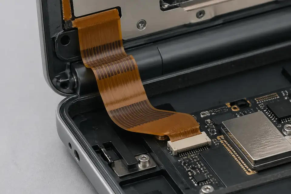
Folded-routing FFC and FPC assembly in a compact folding display path
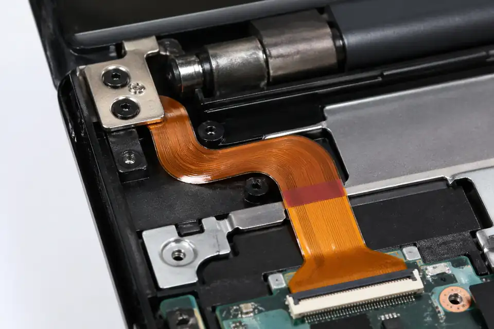
Folded-routing FFC and FPC assembly near a hinge-adjacent route
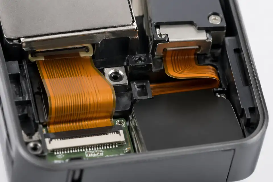
Folded-routing FFC and FPC assembly inside compact consumer electronics
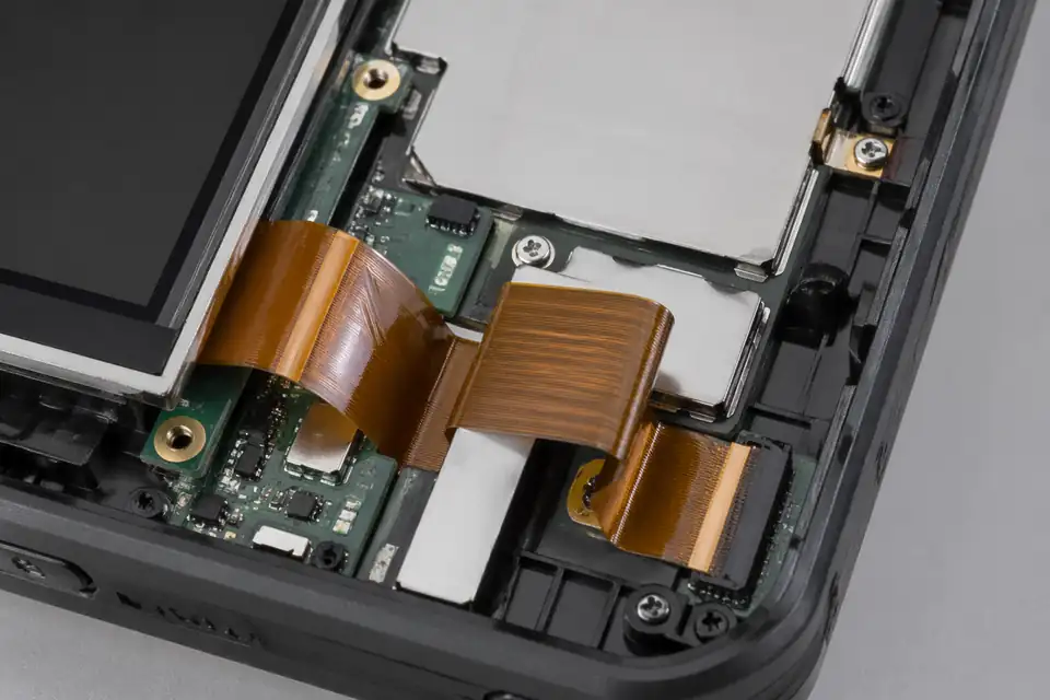
Folded-routing FFC and FPC assembly inside a portable terminal
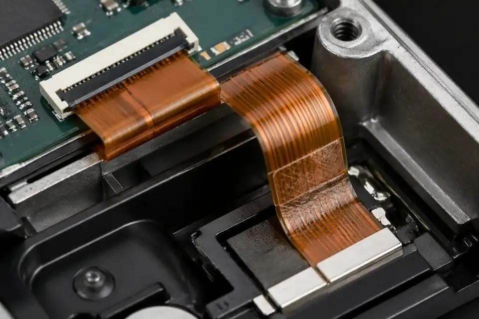
Folded-routing FFC and FPC assembly inside a small module interconnect
Static Fold Route Definition
A folded route is released as installed geometry rather than as a flat cable outline. Each fold line needs a datum, forming direction, protected transition, and tolerance that can be reproduced without converting a static route into an uncontrolled flex zone.
| NO | Route item | Engineering decision | Drawing output |
|---|---|---|---|
| 01 | Motion classification | Confirm that the formed route remains static after installation | Static-use statement and exclusions |
| 02 | Installed path | Define connector exits, turns, supports, and final envelope | Assembly view with route datums |
| 03 | Fold locations | Dimension each fold from a stable feature rather than a trimmed edge alone | Fold-line coordinates |
| 04 | Forming direction | State which face is inside each bend and the intended sequence | Numbered forming diagram |
| 05 | Bend allowance | Set project-approved radius or formed geometry for the selected construction | Bend note tied to material stack |
| 06 | Protected zones | Keep folds away from exposed contacts, stiffener edges, pads, and terminations | No-fold and keep-out dimensions |
| 07 | Retention strategy | Locate tape, clips, guides, or clamps without crushing conductors | Fixing-point and pressure note |
| 08 | Tolerance stack | Budget formed position, cable length, and enclosure variation together | Installed-envelope tolerance |
First-Party Engineering References
- IPC board design standards
Use IPC-2223 as the design-scope reference for flexible and rigid-flex structures, including bend, shielding, and stiffener considerations; obtain detailed requirements from the controlled standard.
- Hirose FH12 series
Use for FH12 connector orientation, pitch, and FPC interface fields only when that series is selected; the page does not establish a universal fold radius.
Formed-Route Failure Review
The dominant risks come from where the formed shape transfers load, not simply from the number of turns. Review the installed part for crease concentration, edge contact, spring-back, and assembly operations that can shift the designed fold.
| NO | Failure mode | Route cause | Design response |
|---|---|---|---|
| 01 | Conductor cracking at a fold | A sharp crease concentrates strain in one line | Use approved forming geometry and inspect the finished bend |
| 02 | Fold migration | Spring-back or installation force moves the formed datum | Add a controlled support outside active conductor areas |
| 03 | Stiffener-edge damage | The first turn begins at the reinforcement transition | Extend the straight protected zone before the fold |
| 04 | Enclosure pinch | The routed envelope intersects a cover, boss, or fastener | Validate the complete tolerance stack in the installed state |
| 05 | Surface abrasion | Cable edges rub against an unfinished guide or chassis wall | Specify edge clearance and protective contact surfaces |
| 06 | Incorrect forming sequence | Operators reverse one fold or trap the route | Provide numbered work instructions and an orientation fixture |
Folded-Route Qualification Plan
Release evidence must show that the flat part can be formed, installed, and retained without damage. The qualification uses representative material and the actual assembly sequence because a flat dimensional report alone cannot validate the final route.
| NO | Check | Execution | Pass condition |
|---|---|---|---|
| 01 | Flat-pattern inspection | Measure cable outline, fold datums, and protected zones before forming | Conforms to released flat drawing |
| 02 | Formed-shape inspection | Compare the finished route with a fixture or controlled overlay | All turns remain inside the installed envelope |
| 03 | Bend-area visual | Inspect both faces and edges under suitable magnification | No crease damage, delamination, or exposed conductor |
| 04 | Electrical test | Run continuity before forming and after installation | No net change or intermittent result |
| 05 | Assembly trial | Install samples using the documented sequence and production tools | No forced fit, trapping, or connector preload |
| 06 | Retention review | Check clips, tape, or guides in the final enclosure | The route remains in position without crushing the cable |
| 07 | Revision package | Archive formed images, fixture identity, material lot, and results | Traceable approval for the active design |
Engineering Capability
Static folded-routing review ties the installed three-dimensional path, fold lines, keep-out zones, connector exits, reinforcement, and assembly sequence to one released definition. Cross-family drawing control is covered in the Related Capability Pages below.
Engineering Capability
Review route path, bend zones, and reinforcement details as one engineering problem.
Treat the first turn and local-fit limits as part of the same release definition.
Quality and Verification Highlights
Focus on repeatable bend behaviour and route execution.
Watch turn zones, reinforcement areas, and local-fit transitions closely in compact builds.
Evidence Chain
Sample Approval and Bend-Review Records
Record the approved fold coordinates, enclosure fit, reinforcement position, formed-surface inspection, and post-install electrical result for the stationary route.
Fold-Pattern Release and Production Records
A folded FFC/FPC route is controlled by its flat pattern, fold geometry, installation sequence, and final orientation; the release package should make each of those conditions unambiguous.
Flat-pattern and fold definition
Record the flat length, fold line, fold direction, angle or formed condition, keep-out area, and connector orientation on the controlled drawing.
First-article route confirmation
Retain the approved sample or installation record showing that the formed cable reaches both connectors without reversing the contact side or loading the fold.
Forming setup and acceptance record
Tie the forming sequence, fixture or reference method, and visual acceptance points to the current part revision when the folded shape is supplied pre-formed.
Shape-preserving packaging
Specify trays, separators, or other support where needed so packing does not flatten the released form, create an extra crease, or change connector orientation.
Certifications / Records Visuals
IMAGES · 04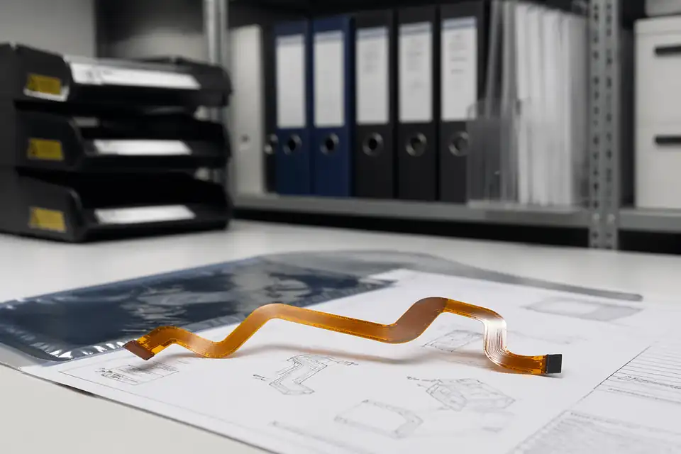
FFC and FPC document-control scene with release files secondary to the flexible assembly
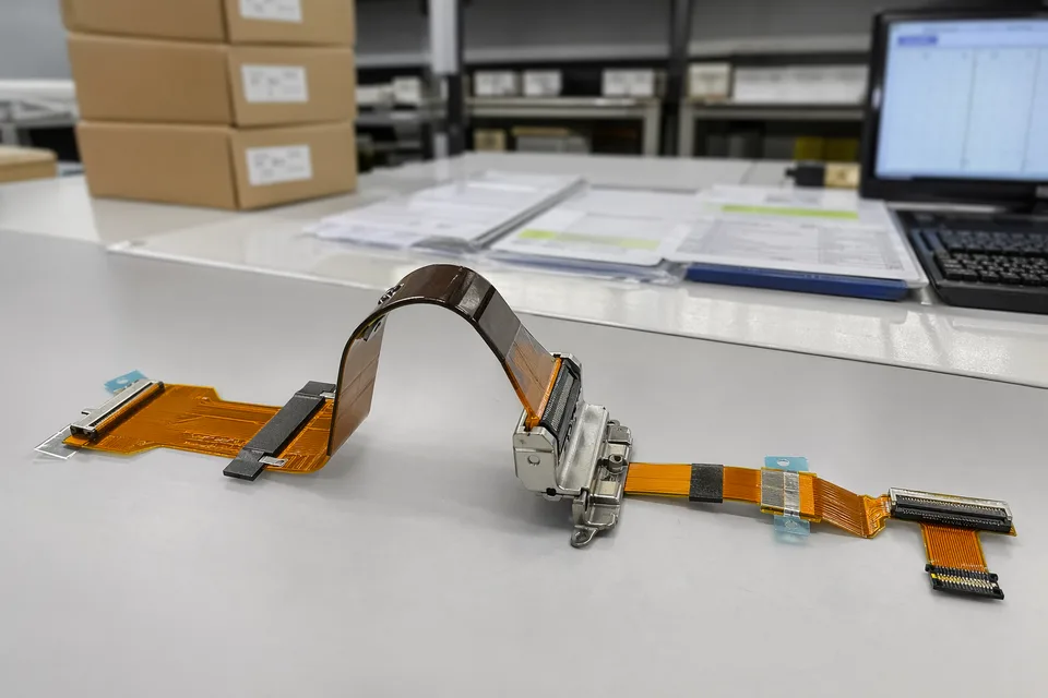
FFC and FPC controlled release record scene with flexible assembly sample foreground
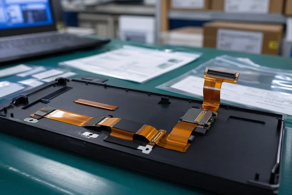
FFC and FPC sample approval archive with protected FPC sample and label props
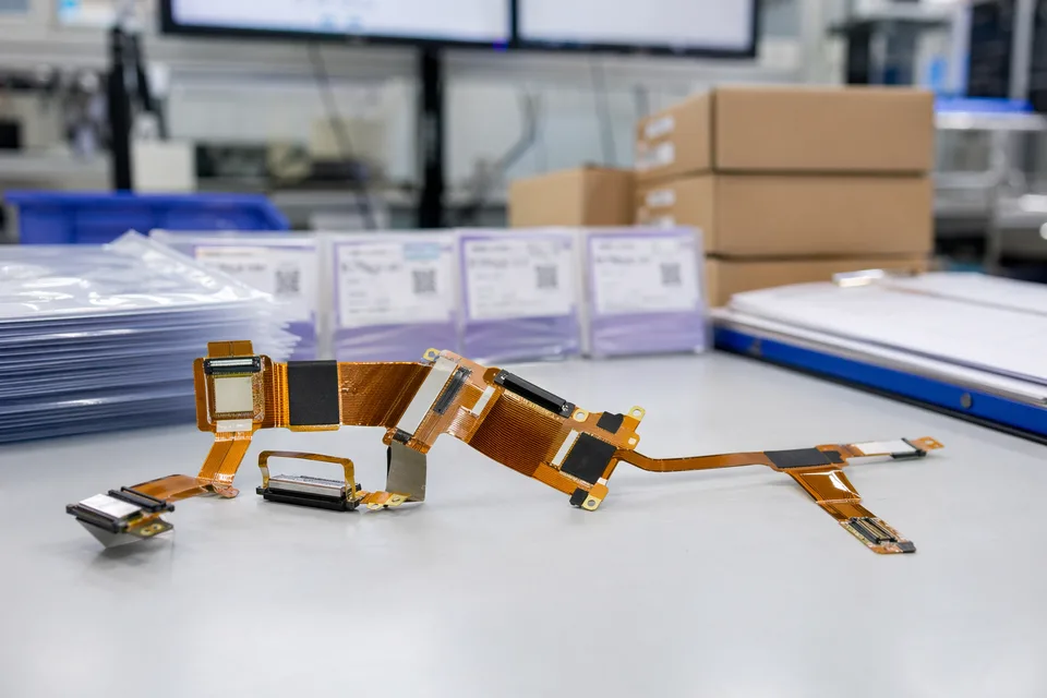
FFC and FPC revision traceability record with cable set, connector lot cards, and folder sleeves
FAQ
Can you review a folded-routing project from an old sample?
Yes. An old sample can show the formed shape, but it does not define the approved fold line, keep-out zone, or installation sequence. Reconstruct those details against the current enclosure and connector drawings before release.
What is the minimum input for a folded-routing quotation?
Send both connector drawings, the installed three-dimensional route, fold coordinates, keep-out zones, reinforcement details, enclosure clearance, project stage, and expected quantity.
How is a static folded route different from a display-hinge route?
A static folded route is formed during assembly and remains in one installed position. A display-hinge route moves repeatedly and needs a defined motion envelope, cycle target, fixture, and monitored failure criteria.
Can one folded route serve several product variants?
Only when fold coordinates, connector exits, enclosure stack-up, reinforcement, and installation sequence remain inside one approved drawing boundary. A shared nominal length alone is not enough.
How should a static folded sample be validated?
Compare the sample with the approved fold drawing and installed enclosure, inspect the formed surface and reinforcement areas, and run the project-defined post-install electrical check. Cyclic flex testing is not implied for a stationary route.