Technical Reference · DISPLAY-HINGE
Display-Hinge Flexible Routing
Custom FFC / FPC Assemblies for Display-Hinge Routes
For hinge-adjacent routes evaluated against a defined motion envelope and cycle plan
EDPcable supports custom FFC and FPC assemblies for display hinges, foldable structures, flip devices, and other routes that move repeatedly in service. Define the motion envelope, minimum allowed bend radius, fixing points, reinforcement, cycle target, test speed, fixture, temperature, monitoring method, and failure criteria as project inputs. A one-time formed route without repeated motion belongs to the static folded-routing direction.
Quick Links
QUICK ACCESSStart with the sections closest to the project structure, interface requirements, and validation scope.
Display-Hinge Product Overview
This direction covers dynamic hinge motion. Bend-life statements are meaningful only when the project defines the installed motion path, cycle target, fixture, environmental conditions, monitored circuit, and failure criteria.
| NO | Item | Typical Range or Meaning |
|---|---|---|
| 01 | Typical Use | Foldable displays, flip devices, hinge-adjacent routes, dynamic flexible paths |
| 02 | Key Inputs | Pitch, connector references, bend zones, reinforcement notes, revision scope |
| 03 | Engineering Focus | Motion envelope, bend radius, first turn, fixing points, reinforcement positions |
| 04 | Quality Focus | Project-defined cycle test, monitored continuity, post-test visual and fit checks |
| 05 | Release Basis | Route geometry, bend notes, reinforcement details, and file-controlled revision scope |
Customer Pain Points
Display-hinge FFC and FPC programs often sound simple because the path is already visible in the product concept. In real RFQ and sample work, the bigger delays usually appear in bend behaviour, reinforcement, route allowance, and revision control rather than in the cable type alone.
| NO | Customer Pain Point | Typical Risk | What Needs Early Confirmation |
|---|---|---|---|
| 01 | Product design issues | The hinge path, bend zones, or reinforcement still do not truly fit the product structure, so the sample becomes only a temporary reference | Route path, bend zones, reinforcement, and installation space |
| 02 | Product quality issues | Repeated-bend execution or local-fit consistency drifts across batches | Structure definition, quality focus, and revision linkage |
| 03 | Lead-time issues | Missing hinge and fit inputs force repeated sample loops and delay release | Route notes, reinforcement details, project stage, and quantity |
| 04 | After-sales issues | It becomes difficult to tell whether the issue came from bend behaviour, revision, or installation conditions | Drawing files, sample approval records, batch labels, and shipment records |
| 05 | Complaint-handling issues | Revision boundaries are unclear, so issue tracing stays slow | Revision confirmation, batch correspondence, and inspection records |
| 06 | Pricing issues | A broad “display-hinge route” request turns into repeated pricing changes once real bend and fit constraints surface | Structure complexity, material expectations, quantity, and timing |
Product Applications
Display-hinge FFC and FPC is not only a layout style. It usually appears in device programs where bend life, route allowance, reinforcement, and local-fit judgement all matter. The five scenes below are the most common application contexts.
| NO | Application Scene | Scene Focus | Typical Concerns |
|---|---|---|---|
| 01 | Laptop hinge routes | Open-close movement stays most sensitive | Bend radius, first turn, fixing points |
| 02 | 2-in-1 hinge links | Route allowance is more complex | Route stability, revision boundaries, structure protection |
| 03 | Foldable-display devices | Flexibility and repeated movement both matter | Bend zones, reinforcement positions, release logic |
| 04 | Tablet stand structures | The enclosure is thinner | Route length, fixing method, assembly efficiency |
| 05 | Compact display terminals | Hinge-adjacent routes depend more on long-term stability | Batch consistency, test rhythm, after-sales traceability |
Application Scene Visuals
IMAGES · 05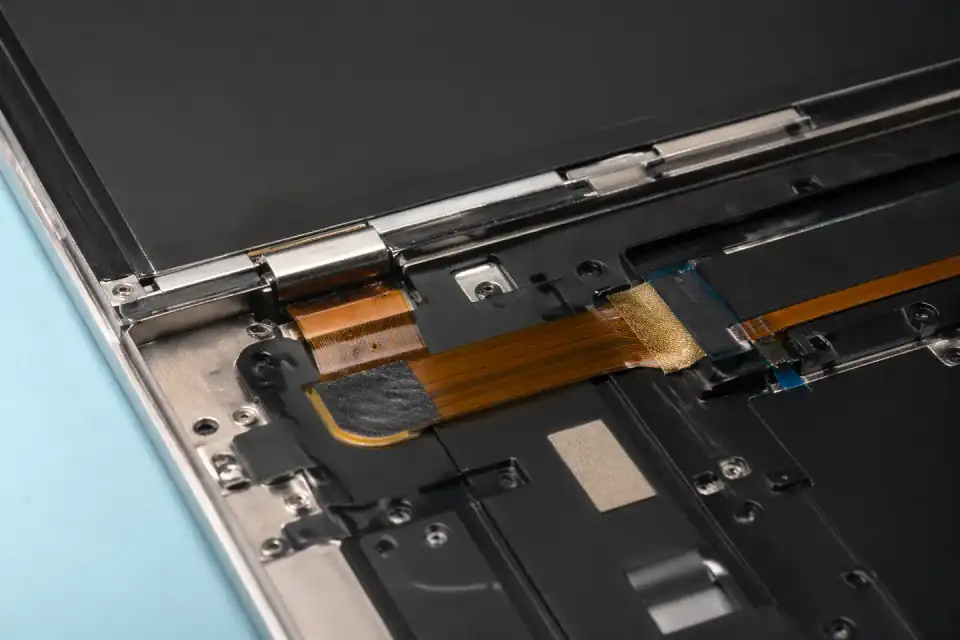
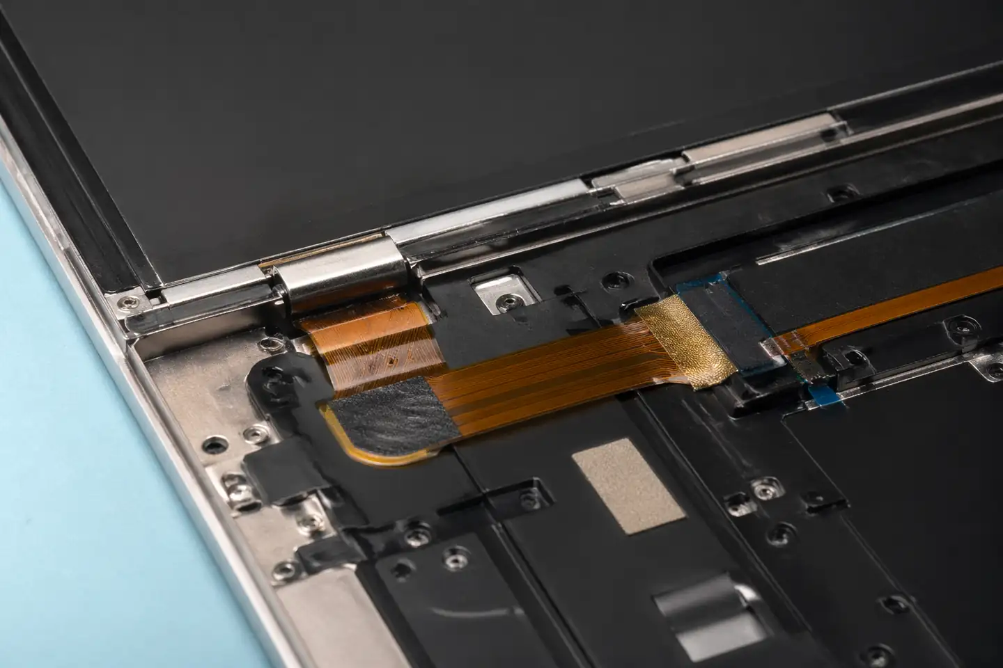
FFC and FPC assembly routed through a laptop hinge path
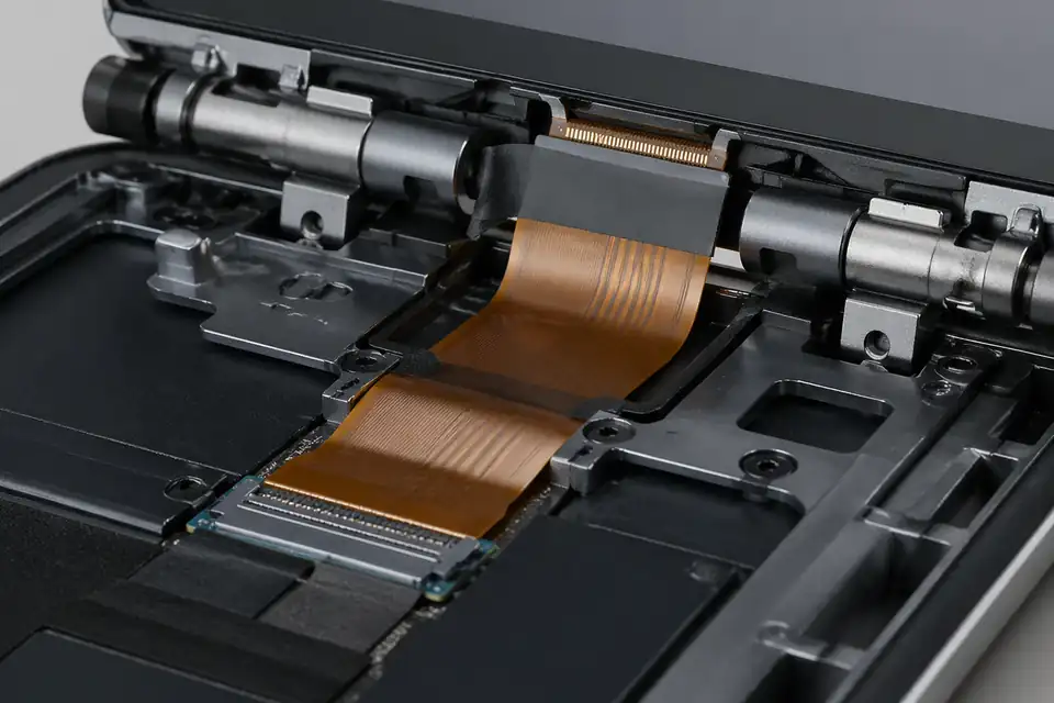
FFC and FPC assembly inside a 2-in-1 hinge interconnect
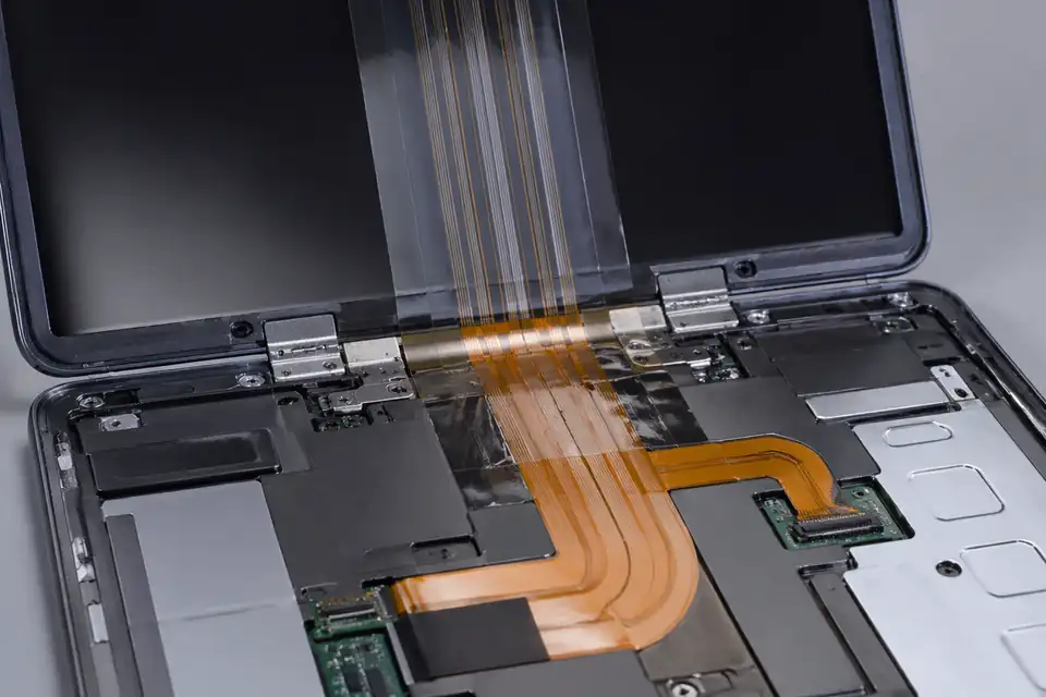
FFC and FPC assembly inside a foldable display device
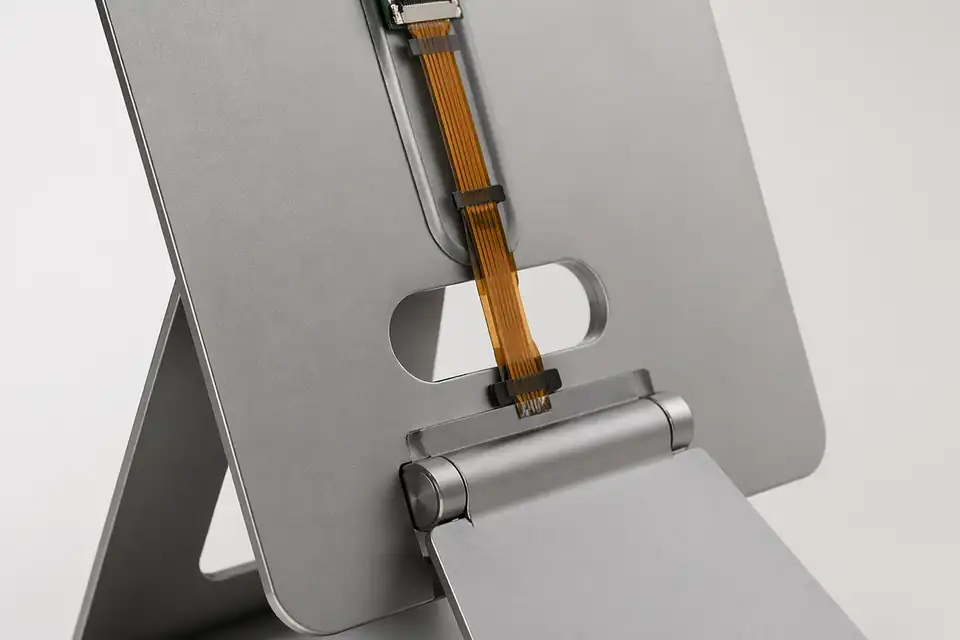
FFC and FPC assembly inside a thin tablet support structure
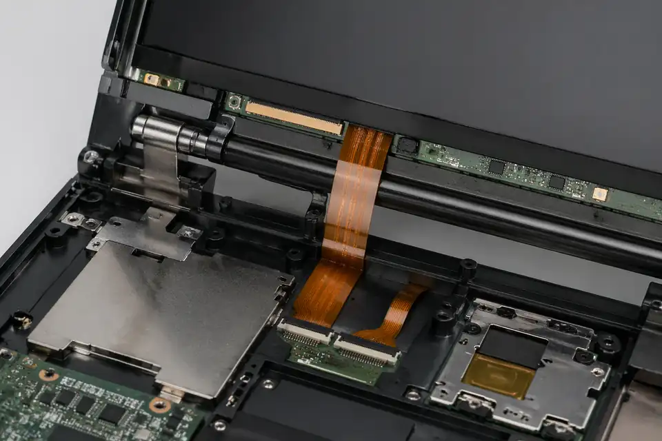
FFC and FPC assembly near a compact display terminal hinge zone
Display-Hinge Motion Definition
A hinge cable cannot be specified by flex-cycle count alone. The motion path, axis, active length, bend direction, twist, connector anchoring, and end positions define the strain history that the assembly must survive.
| NO | Motion parameter | Definition required | Qualification input |
|---|---|---|---|
| 01 | Hinge kinematics | Document axis location, travel range, and intermediate path | Representative mechanism or motion model |
| 02 | Active flex length | Identify the portion intended to move repeatedly | Dimensioned dynamic zone |
| 03 | Bend geometry | Set project-approved radius and curvature for each position | Position-specific route sections |
| 04 | Neutral position | Choose the assembly state with minimal cable preload | Installation datum and fixture setup |
| 05 | Twist allowance | Quantify torsion separately from planar bending | Three-dimensional route definition |
| 06 | Connector anchoring | Keep motion-induced loads away from cable tails, stiffeners, and contacts | Clamp and strain-relief drawing |
| 07 | Abrasion control | Define guides, edge finishes, and clearances through full travel | Contact-surface specification |
| 08 | Life target | Set cycles, rate, dwell, powered state, and failure criteria | Approved qualification protocol |
| 09 | Environment | Select temperature or humidity conditions relevant to actual use | Program-specific test sequence |
First-Party Engineering References
- IPC board design standards
Use IPC-2223 for flexible-board design categories and controlled terminology; a hinge-specific radius and cycle target must come from the selected construction and project qualification.
- Molex FFC/FPC connector portfolio
Use for connector selection fields only. The portfolio page does not establish dynamic-flex endurance for a display-hinge cable.
Hinge-Life Failure Review
Dynamic damage accumulates where the real mechanism departs from the idealized bend. Inspection focuses on changing curvature, tension at travel limits, rubbing surfaces, and torsion that moves the fatigue point toward a connector transition.
| NO | Failure mode | Motion mechanism | Design control |
|---|---|---|---|
| 01 | Progressive conductor fatigue | Repeated curvature concentrates in a short active zone | Increase usable flex length and stabilize the intended motion path |
| 02 | Reverse-bend crease | The cable forms an S-bend or snaps through during travel | Guide the route through every intermediate position |
| 03 | End-of-travel tension | Cable length or anchoring pulls at the fully open or closed state | Set the cable length and neutral position, then verify both travel limits without tensile preload |
| 04 | Edge abrasion | The moving cable rubs a guide, hinge barrel, or enclosure edge | Control clearance, surface finish, and guide geometry |
| 05 | Torsional delamination | Twist combines with bending beyond the qualified path | Separate or limit torsion in the mechanism definition |
| 06 | Connector-transition failure | Dynamic load reaches the stiffener edge or mating tail | Anchor the moving section before the connector transition |
Dynamic Hinge Qualification Plan
Cycle testing is meaningful only when the fixture reproduces the production mechanism. The protocol records route position, speed, dwell, electrical monitoring, environment, and teardown criteria so results remain tied to one construction and motion profile.
| NO | Qualification step | Execution | Acceptance evidence |
|---|---|---|---|
| 01 | Fixture correlation | Compare fixture axis, guides, anchors, and travel with production hardware | Documented kinematic equivalence |
| 02 | Initial electrical baseline | Measure continuity and specified resistance before cycling | Values within project baseline limits |
| 03 | Dynamic monitoring | Monitor assigned circuits during repeated motion where practical | No intermittent opens or shorts |
| 04 | Position inspections | Observe route at closed, mid-travel, and open positions | No unintended crease, tension, twist, or contact |
| 05 | Periodic visual checks | Inspect surfaces and transitions at planned intervals | No progressive abrasion or delamination beyond criteria |
| 06 | Post-cycle electrical test | Repeat the complete net test after the target sequence | Meets released electrical limits |
| 07 | Teardown examination | Inspect active zone, anchor points, and connector transitions | No disqualifying structural damage |
| 08 | Qualification report | Record fixture revision, sample build, environment, cycles, and findings | Approval applies only to the tested configuration |
Engineering Capability
Dynamic hinge engineering ties the motion envelope, bend radius, first turn, fixing points, reinforcement, and connector exits to a project-defined cycle test. Cross-family drawing control is covered in the Related Capability Pages below.
Engineering Capability
Review route geometry, bend zones, and reinforcement details as one engineering problem.
Treat hinge allowance and local-fit limits as part of the same release definition.
Quality and Verification Highlights
Focus on repeatable bend behaviour and route execution.
Watch turn zones, reinforcement areas, and local-fit transitions closely in compact builds.
Evidence Chain
Sample Approval and Bend-Review Records
Record the approved hinge geometry, fixture, cycle conditions, monitored result, reinforcement position, and post-test inspection against the released revision.
Dynamic-Route Release and Validation Records
A display-hinge route needs records that separate the moving zone from fixed sections and connect the approved material stack, anchor points, bend condition, and cycle evaluation to one revision.
Moving-zone route definition
Mark fixed points, the active bend zone, first-exit directions, available hinge space, and connector orientation on the controlled route drawing.
Installed cycle-evaluation record
Retain the fixture condition, bend angle, cycle target, monitoring method, and post-test inspection result used to approve the project-specific route.
Material and route revision control
Distinguish changes to conductor stack, reinforcement, overall length, adhesive or fixing features, because each can alter hinge behavior even when the connectors stay unchanged.
Pre-form and handling protection
Define shipment support and handling notes where a pre-formed route must arrive without a new crease, reversed bend, or load at the connector exit.
Certifications / Records Visuals
IMAGES · 04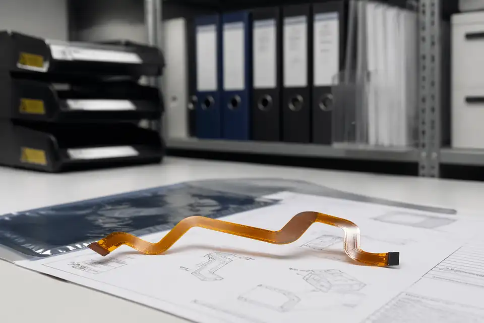
FFC and FPC document-control scene with release files secondary to the flexible assembly
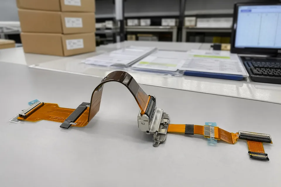
FFC and FPC controlled release record scene with flexible assembly sample foreground
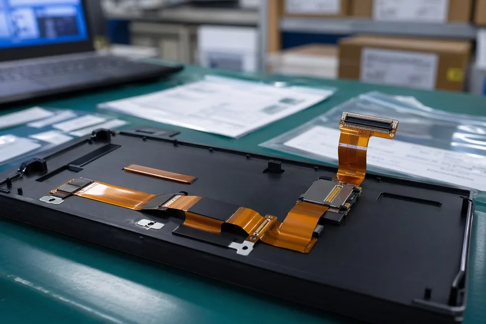
FFC and FPC sample approval archive with protected FPC sample and label props
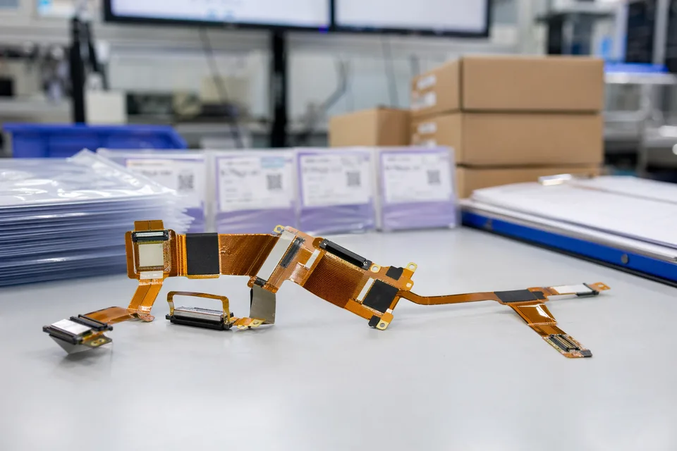
FFC and FPC revision traceability record with cable set, connector lot cards, and folder sleeves
FAQ
Can you review a display-hinge project from an old sample?
An old sample can show connector and envelope clues, but it cannot establish dynamic life. The current hinge motion, fixing points, bend radius, cycle target, fixture, and monitored failure criteria still need to be defined.
What is the minimum input for a display-hinge quotation?
Send both connector drawings, hinge geometry, motion angle, fixing points, bend-radius limit, cycle target, test conditions, project stage, and expected quantity.
How is a display-hinge route different from a static folded route?
A display-hinge route moves repeatedly and is evaluated against defined cycle conditions. A static folded route is formed during installation and validated in its final stationary position without implying dynamic life.
Can one display-hinge route serve several product variants?
Only when the hinge geometry, motion envelope, fixing points, connector exits, and cycle conditions remain inside one approved validation boundary. Shared length or pitch alone is not enough.
What makes a hinge cycle result comparable?
Record the test fixture, motion angle, speed, bend radius, temperature, cycle count, monitored circuit, interruption threshold, and post-test inspection. Results from different conditions should not be treated as equivalent.