Technical Reference · 0-5MM-1-0MM-PITCH
FFC / FPC Pitch Selection
Custom 0.5mm and 1.0mm Pitch FFC / FPC Assemblies
For flexible interconnect RFQs where pitch choice, connector fit, stiffener design, and route release need one review
EDPcable supports custom 0.5mm and 1.0mm pitch FFC / FPC assemblies for display modules, compact devices, control panels, and routed flexible links. Pitch-specific RFQs need a sharper review than broad fine-pitch discussions: pitch, conductor count, contact direction, stiffener thickness, plating expectations, bend area, and installed clearance should be checked together before sample release.
Quick Links
QUICK ACCESSStart with the sections closest to the project structure, interface requirements, and validation scope.
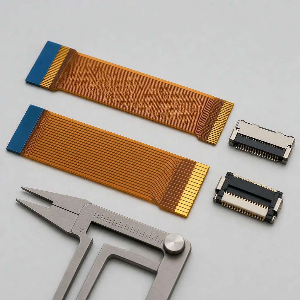
0.5mm / 1.0mm Pitch Product Overview
Use this direction when the nominal 0.5mm or 1.0mm pitch is already fixed. The review connects that pitch to the mating-connector drawing, conductor count, contact side, exposed-contact geometry, stiffener, bend path, and release evidence.
| NO | Item | Typical Range or Meaning |
|---|---|---|
| 01 | Pitch Focus | 0.5mm and 1.0mm FFC / FPC, with adjacent fine-pitch options handled by project review |
| 02 | Common Inputs | Pitch, conductor count, contact direction, connector family, length, stiffener notes |
| 03 | Engineering Focus | Connector fit, exposed conductor direction, stiffener thickness, bend zone, installed clearance |
| 04 | Quality Focus | Dimension checks, contact exposure, stiffener placement, visual inspection, continuity |
| 05 | Release Basis | Drawing, sample approval, inspection criteria, and revision-controlled pitch definition |
Engineering Inputs
Use these items as first-round review inputs so the discussion does not rely on the page label alone.
Send pitch, conductor count, total length, and contact direction.
Include connector references, mating photos, or old sample photos when available.
Add stiffener thickness, exposed conductor, plating, bend-zone, and route-space notes.
State project stage, sample quantity, batch quantity, and target timing.
Explain any variant or replacement boundaries that affect the pitch definition.
Customer Pain Points
0.5mm and 1.0mm pitch FFC / FPC projects often sound straightforward once the product or route category is known. In real RFQ and sample work, delays usually appear in route fit, structure judgement, and revision control rather than in the label alone.
| NO | Customer Pain Point | Typical Risk | What Needs Early Confirmation |
|---|---|---|---|
| 01 | Product design issues | The connector path, structure, or local fit still does not truly match the 0.5mm and 1.0mm pitch FFC / FPC build, so the sample becomes only a temporary reference | Connector references, route path, structure boundaries, and installation space |
| 02 | Product quality issues | Execution, local fit, or batch consistency drifts across repeated 0.5mm and 1.0mm pitch FFC / FPC builds | Structure definition, quality focus, and revision linkage |
| 03 | Lead-time issues | Missing inputs force repeated sample loops and slow quotation, release, and batch timing | Connector data, route notes, project stage, quantity, and timing |
| 04 | After-sales issues | It becomes difficult to tell whether the issue came from structure, revision, or installed conditions | Drawing files, sample approval records, batch labels, and shipment records |
| 05 | Complaint-handling issues | Revision boundaries are unclear, so issue tracing stays slow | Revision confirmation, batch correspondence, and inspection records |
| 06 | Pricing issues | A broad request turns into repeated pricing changes once real fit constraints surface | Structure complexity, material expectations, quantity, and delivery boundaries |
Product Applications
0.5mm and 1.0mm pitch FFC / FPC assemblies appear in device programs where connector fit, contact direction, stiffener geometry, route clearance, and revision scope must be confirmed together.
| NO | Application Scene | Scene Focus | Typical Concerns |
|---|---|---|---|
| 01 | Display module links | pitch and contact direction matched to panel connector requirements | connector fit, exposed conductor side, and route clearance |
| 02 | Compact control panels | short flexible routes with clean stiffener positioning | stiffener thickness, insertion depth, and local bend space |
| 03 | Handheld electronics | lighter flexible interconnects inside constrained housings | handling protection, bend radius, and revision control |
| 04 | Replacement FFC / FPC routes | matching old pitch and conductor count to current connector options | near-match pitch risk and sample ambiguity |
| 05 | Multi-revision products | keeping one pitch definition stable across device versions | connector substitutions, route changes, and file linkage |
Application Scene Visuals
IMAGES · 05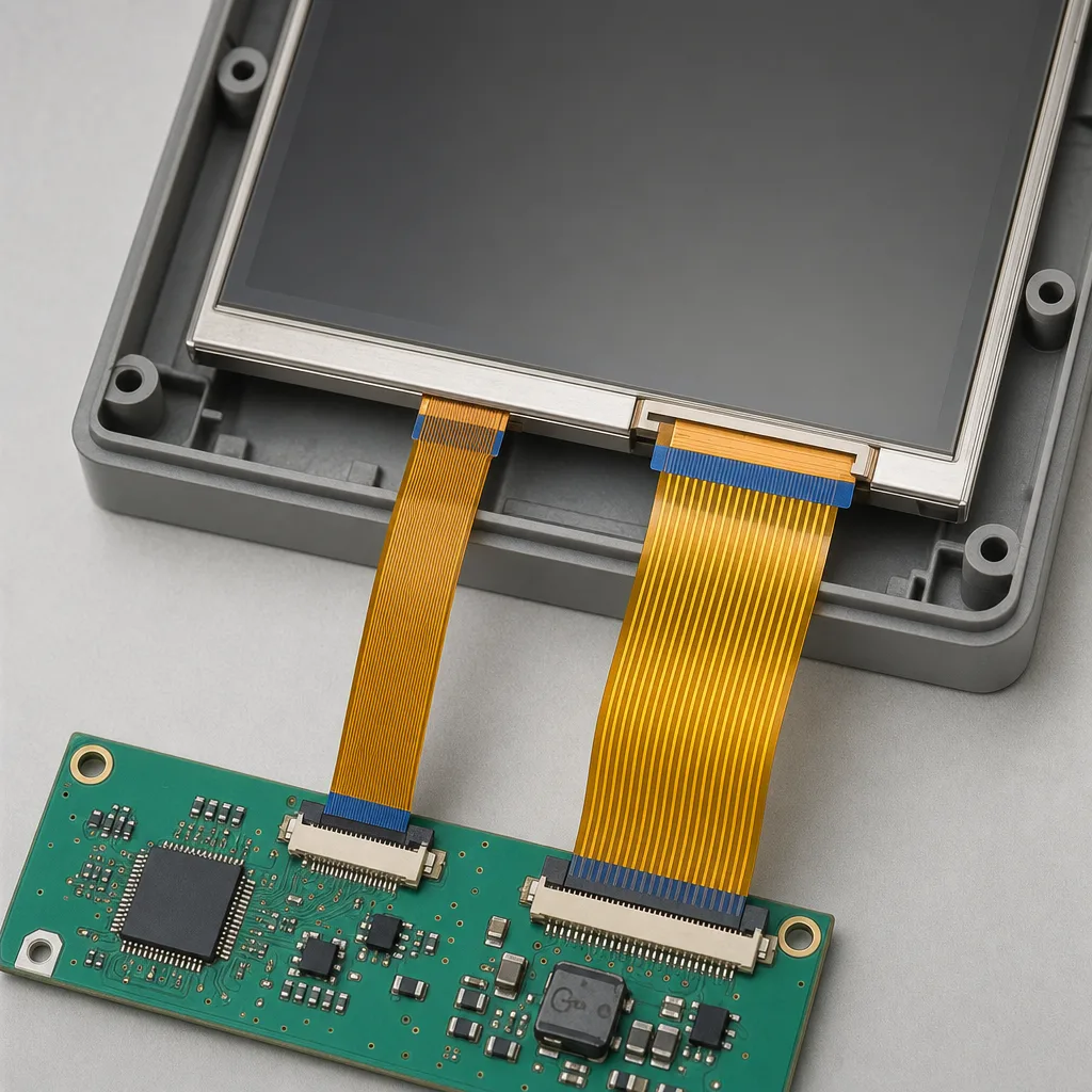
FFC and FPC display-module link line-art with 0.5mm and 1.0mm pitch and contact direction matched to a panel connector
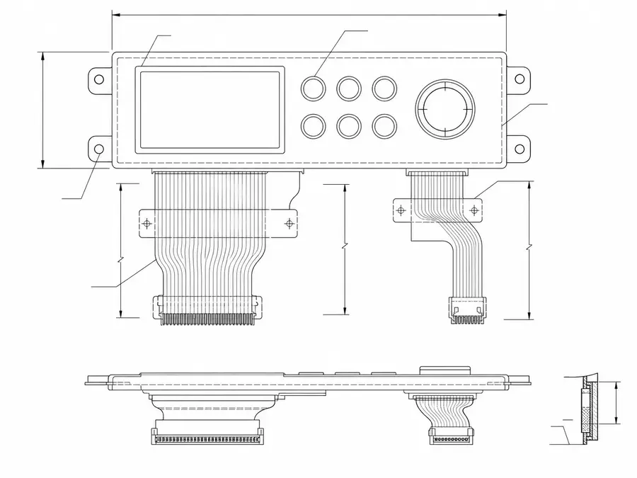
Compact control-panel FFC and FPC route line-art with short flexible paths and clean stiffener positioning
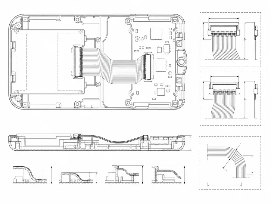
Handheld-electronics FFC and FPC interconnect line-art inside a constrained housing with light flexible routing
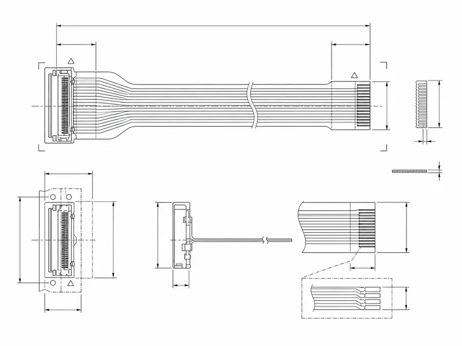
Replacement FFC and FPC route line-art matching old pitch and conductor count to a current connector
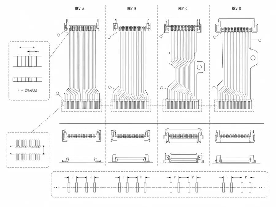
Multi-revision FFC and FPC layout line-art keeping one pitch definition stable across device versions
0.5 mm / 1.0 mm Interface Matrix
The 0.5 mm and 1.0 mm labels identify candidate connector centerlines, not interchangeable cable recipes. The released assembly must inherit its pitch, contact count, tail thickness, contact side, and insertion geometry from one exact mating-connector definition.
| NO | Selection field | 0.5 mm / 1.0 mm decision | Required source |
|---|---|---|---|
| 01 | Connector family | Select the exact series before freezing the cable tail | Manufacturer part drawing |
| 02 | Nominal pitch | Use the centerline specified by the selected mating part | Connector specification |
| 03 | Contact count | Match populated conductors to the exact position count | Released pin assignment |
| 04 | Contact side | Define the exposed-contact face at each cable end from a named viewing direction | Cable end-view detail |
| 05 | Tail thickness | Set the complete mating stack, including stiffener and adhesive | Connector and cable tolerance stack |
| 06 | Insertion geometry | Dimension exposed length, shoulder, and insertion datum | Controlled tail drawing |
| 07 | Electrical use | Assign signal, ground, and power according to project limits | Netlist and current budget |
| 08 | Route allowance | Reserve straight entry and project-approved bend clearance | Installed assembly drawing |
First-Party Engineering References
- Molex FFC/FPC connector portfolio
Use for comparing portfolio-level pitch, circuit, orientation, and actuator options; product-level ratings require the exact Molex part documentation.
- Hirose FH12 series
The page publishes FH12 0.5 mm and 1.0 mm series options and related fields; those values apply only within the listed FH12 variants.
Pitch-Selection Failure Review
Near-match parts can appear compatible during visual inspection while failing at the contact line or tail stack. This review treats pitch, position count, contact exposure, and stiffener geometry as one mating system.
| NO | Failure mode | Selection error | Containment |
|---|---|---|---|
| 01 | Near-match pitch substitution | A visually similar cable is specified for a different connector | Lock exact connector and cable part references together |
| 02 | Wrong contact face | End views use inconsistent orientation conventions | Add connector-facing and cable-facing views with Pin 1 |
| 03 | Tail too thick or thin | Stiffener and adhesive were excluded from stack review | Measure the completed mating area, not base film alone |
| 04 | Insufficient contact overlap | Exposure or insertion shoulder does not reach the spring zone | Dimension insertion datum from the connector drawing |
| 05 | Conductor overload | Power allocation is copied from another pitch or construction | Set loading from the chosen parts and project derating |
| 06 | Entry-angle damage | The route turns before the cable has cleared the connector | Provide a straight lead-in and installation guidance |
Pitch-Specific Verification Plan
The sample is verified as a matched connector-and-cable pair. Inspection records identify the exact mating part so a passing result cannot be reused for a different 0.5 mm or 1.0 mm series without review.
| NO | Verification | Evidence | Release criterion |
|---|---|---|---|
| 01 | Source-document check | Connector specification, cable drawing, and BOM comparison | Same family, pitch, position count, and active revision |
| 02 | Optical pitch measurement | Calibrated measurement across the contact pattern | Within released tail tolerance |
| 03 | Completed-tail thickness | Measure stiffener and adhesive stack at defined locations | Fits specified connector window |
| 04 | Contact orientation check | Compare both cable ends with the approved end views | Exposure and Pin 1 match the drawing |
| 05 | Mating demonstration | Seat and latch samples in the intended connector | Full engagement without buckling or scoring |
| 06 | Point-to-point continuity | Test all populated conductors | Matches released map |
| 07 | First-article documentation | Capture measurements, photographs, connector P/N, and test record | Customer or internal approval before production release |
Engineering Capability
Pitch-specific engineering ties the mating-connector drawing, conductor count, contact orientation, exposed-contact geometry, stiffener, and installed route to one released definition. Cross-family drawing control is covered in the Related Capability Pages below.
Engineering Capability
Review route path, connector references, and local fit together for the 0.5mm and 1.0mm pitch FFC / FPC build.
Quality and Verification Highlights
Watch local-fit zones, connector exits, and route transitions specific to 0.5mm and 1.0mm pitch FFC / FPC installs.
Files and Batch Support
0.5mm and 1.0mm pitch FFC / FPC work has its own document layer around route and fitting boundaries. Cross-family file control, batch traceability, and certification practice are summarised in the Related Capability Pages.
0.5mm and 1.0mm pitch FFC / FPC route and fitting-boundary records
Capture the route path, local fit, and installation-space limits that are specific to the 0.5mm and 1.0mm pitch FFC / FPC build so later structural differences can be traced back to the right layer of change.
Certifications / Records Visuals
IMAGES · 04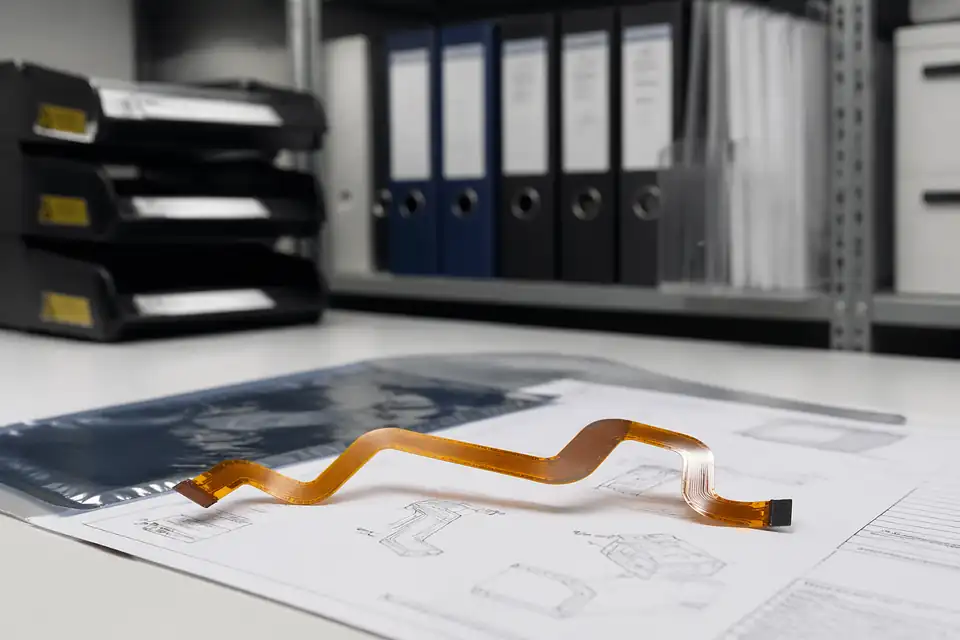
FFC and FPC document-control scene with release files secondary to the flexible assembly
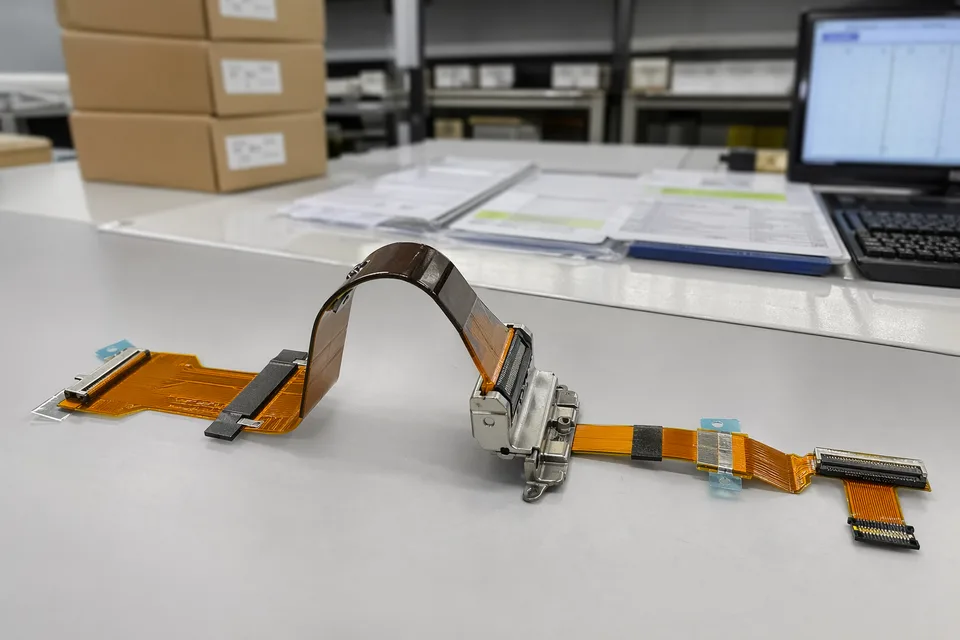
FFC and FPC controlled release record scene with flexible assembly sample foreground
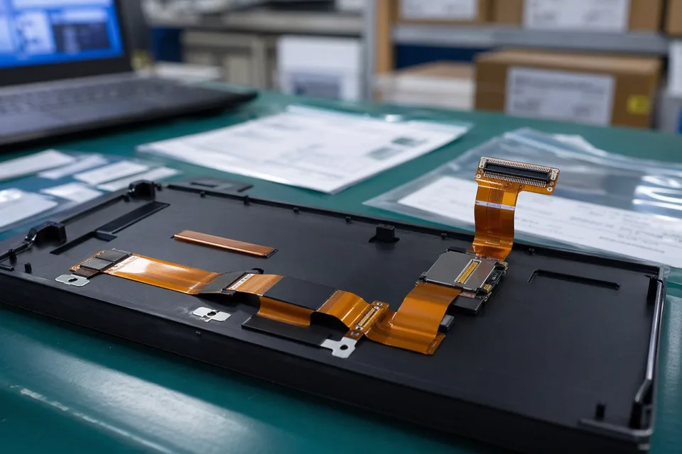
FFC and FPC sample approval archive with protected FPC sample and label props
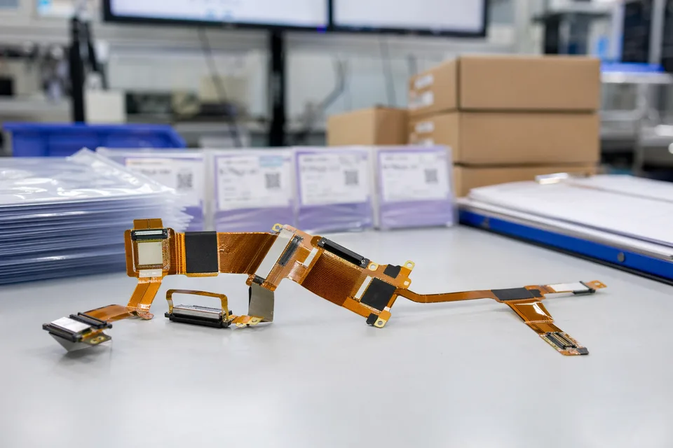
FFC and FPC revision traceability record with cable set, connector lot cards, and folder sleeves
FAQ
Should I choose 0.5mm or 1.0mm pitch first?
The choice depends on connector availability, conductor count, local space, insertion handling, and bend geometry. 0.5mm saves space but usually needs tighter handling and tolerance review.
When should the broader fine-pitch direction be used?
Use the broader fine-pitch direction while density, connector family, or nominal pitch is still being selected. The 0.5mm / 1.0mm checklist applies once either pitch is fixed in the interface definition.
What details are needed for a quote?
Pitch, conductor count, length, contact direction, connector reference, stiffener notes, bend path, quantity, and timing are the most useful first inputs.
Can you match an old FFC or FPC sample?
Yes. Send photos, measurements, conductor count, contact-side details, and device context. Old samples still need connector and revision confirmation.
Can one pitch definition cover several product versions?
Sometimes, but only when connector references, contact direction, stiffener, length, and route boundaries stay inside one approved definition.