Technical Reference · FPC-TO-WIRE-HYBRID
FPC-to-Wire Hybrid Capability
Custom FPC-to-Wire Hybrid Interconnects
For projects that need a controlled transition from FPC pads to discrete wires
EDPcable supports custom FPC-to-wire hybrid interconnects where the flexible circuit side cannot be treated as a normal FFC / FPC strip and the wire side cannot be treated as a separate harness. The transition area, pad layout, solder or termination method, reinforcement, strain relief, inspection criteria, and release records should be defined together before the assembly is quoted or sampled.
Quick Links
QUICK ACCESSStart with the sections closest to the project structure, interface requirements, and validation scope.
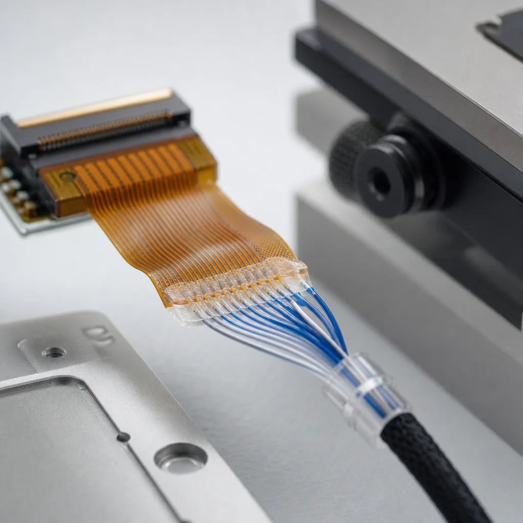
FPC-to-Wire Hybrid Product Overview
FPC-to-wire hybrid work is a capability-led direction. The review should prove that the transition zone can be built, protected, inspected, and repeated, not only that the FPC and wire materials are available.
| NO | Item | Typical Range or Meaning |
|---|---|---|
| 01 | Typical Structure | FPC pad area connected to discrete wires, micro harnesses, or local connector leads |
| 02 | Key Inputs | FPC drawing, pad geometry, wire gauge, termination method, reinforcement notes, route path |
| 03 | Engineering Focus | Transition-zone design, solder or termination consistency, strain relief, bend protection |
| 04 | Quality Focus | Visual inspection, pull or handling checks where applicable, continuity, sample approval records |
| 05 | Release Basis | Drawing, process notes, inspection criteria, sample approval, and batch-linked records |
Capability Review Inputs
Use these items as first-round review inputs so the discussion does not rely on the page label alone.
Send FPC drawing, pad layout, wire gauge, and route path.
Include termination method expectations, reinforcement notes, and strain-relief limits.
Add old sample photos or device context when drawings are incomplete.
State inspection, record, packaging, or traceability needs.
List sample quantity, batch quantity, timing target, and revision boundaries.
Customer Pain Points
FPC-to-wire hybrid projects often fail to move quickly because the transition area is not defined early enough. A quote based only on FPC material and wire gauge misses the real manufacturing risk.
| NO | Customer Pain Point | Typical Risk | What Needs Early Confirmation |
|---|---|---|---|
| 01 | Transition-zone uncertainty | Pad layout, wire exit, or reinforcement leaves the joint exposed to handling stress | Pad geometry, wire gauge, route direction, reinforcement method, and keep-out area |
| 02 | Process repeatability risk | A sample can be made, but solder or termination execution is difficult to repeat | Process window, operator fixture, inspection criteria, and sample approval basis |
| 03 | Route and strain-relief conflict | The hybrid joint sits too close to a bend, clamp, or moving area | Bend zone, fixing point, strain-relief direction, and installed clearance |
| 04 | Inspection ambiguity | The customer and factory inspect different features, so sample approval does not protect batch release | Visual criteria, continuity scope, handling checks, and record format |
| 05 | Revision and complaint risk | Later failures are hard to trace because the process basis was not tied to the active revision | Drawing revision, process notes, batch labels, and shipment records |
| 06 | Pricing instability | The RFQ changes after the transition method, reinforcement, or inspection plan becomes clear | Joint complexity, material selection, quantity, sample timing, and batch rhythm |
Transition Zone and Process Control
The hybrid transition needs to be treated as its own controlled area. A practical review connects electrical continuity with mechanical support, inspection visibility, and repeatable operator execution.
| NO | Review Area | What We Check | Why It Matters |
|---|---|---|---|
| 01 | FPC pad and land pattern | Pad size, spacing, coverlay opening, solderable area, and orientation | The pad geometry decides whether the wire transition can be made cleanly and inspected later |
| 02 | Wire and termination method | Wire gauge, insulation, strip length, solder or termination approach, and exit direction | The wire side controls handling force, bend direction, and repeatability |
| 03 | Reinforcement and strain relief | Stiffener, adhesive, encapsulation, tube, tape, or fixture concept where applicable | The joint needs protection from pull, bend, and assembly handling |
| 04 | Inspection criteria | Visual acceptance, continuity, dimensional checks, and sample approval output | Shared criteria reduce disagreement between one approved sample and later batches |
| 05 | Release records | Drawing revision, process notes, sample record, inspection output, and batch labels | Traceable records make repeat orders and issue handling more practical |
Product Applications
FPC-to-wire hybrid assemblies usually appear when a compact flexible section must connect to a more serviceable or routeable wire harness. The scenes below are common starting points for RFQ review.
| NO | Application Scene | Scene Focus | Typical Concerns |
|---|---|---|---|
| 01 | Compact sensor modules | Small FPC pads transition into discrete leads | Joint protection, pad size, and handling during assembly |
| 02 | Display-adjacent subassemblies | Flexible section exits a panel area before joining wire routing | Bend distance, strain relief, and local clearance |
| 03 | Medical and diagnostic modules | Hybrid route needs clear release records and careful handling | Inspection evidence, batch labels, and revision scope |
| 04 | Wearable or handheld devices | Thin FPC section needs a protected wire transition | Bend zone, adhesive support, and enclosure fit |
| 05 | Replacement or repair programs | Legacy hybrid part must be matched without complete drawings | Old sample ambiguity, near-match risk, and sample approval |
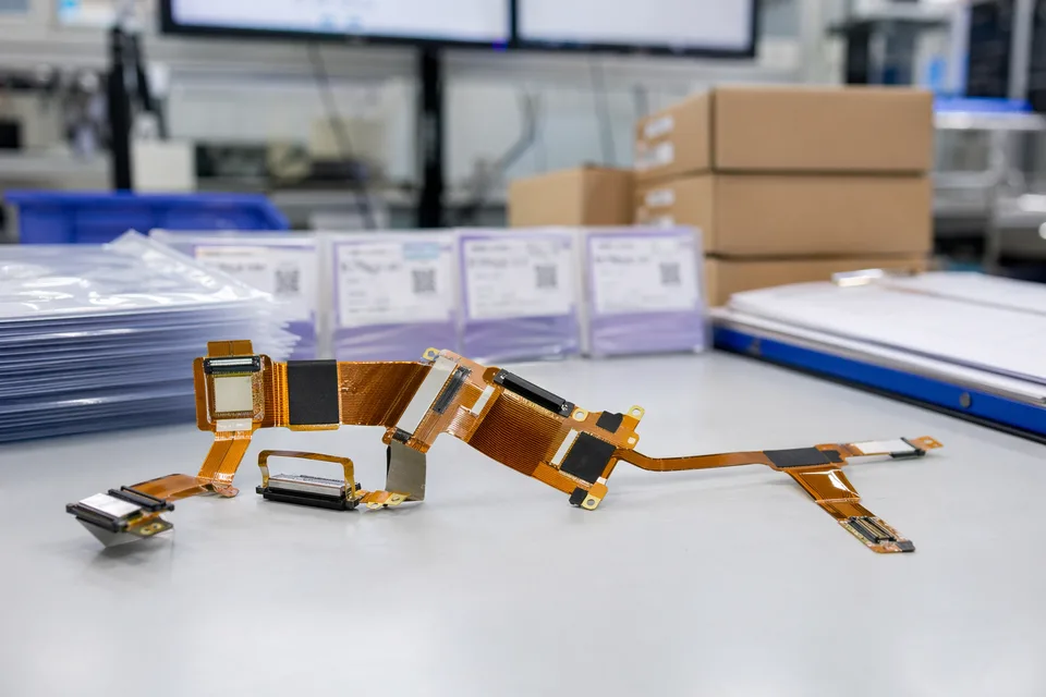
Hybrid Transition Visuals
IMAGES · 04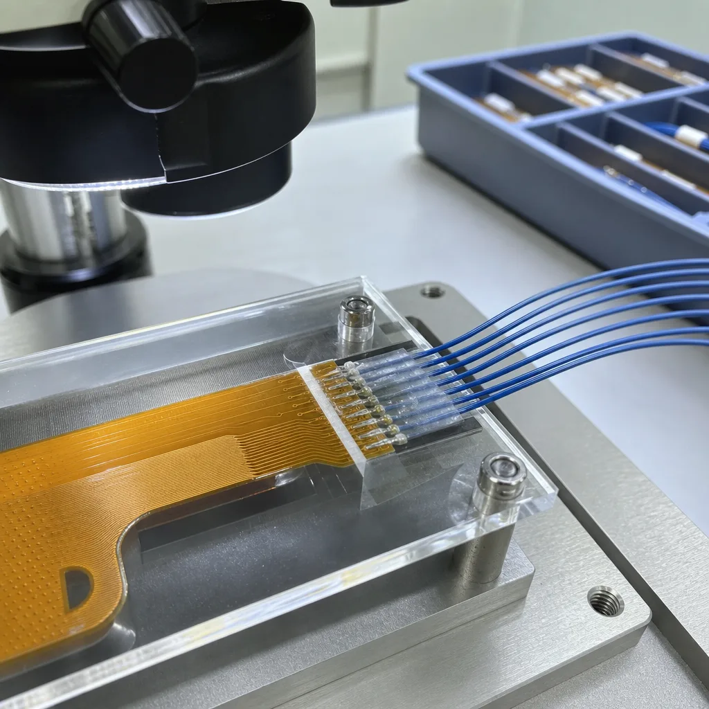
Close-up line-art of an FPC pad-to-wire transition with a reinforced joint and inspection visibility
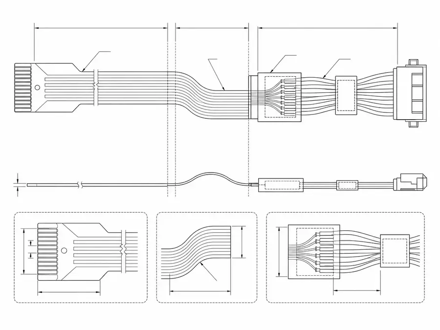
FPC-to-wire hybrid assembly route line-art with the bend zone separated from the transition area
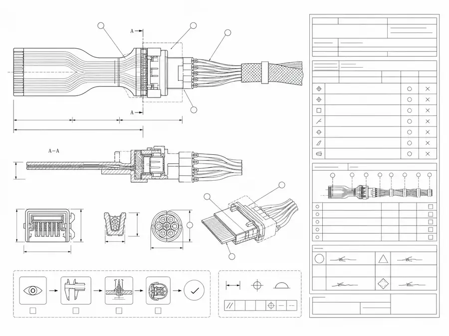
FPC-to-wire hybrid joint with inspection and sample-approval records
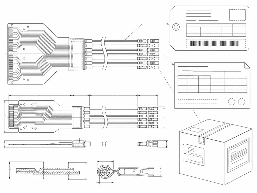
Batch-label and shipment-record line-art connected to a released FPC-to-wire hybrid revision
Hybrid Transition Definition Matrix
An FPC-to-wire assembly is governed by its transition zone. The FPC land pattern, wire preparation, joining process, reinforcement, and load path must be defined together at a common mechanical and electrical interface so electrical acceptance does not conceal a mechanically fragile joint.
| NO | Transition element | Definition needed | Controlled record |
|---|---|---|---|
| 01 | FPC land pattern | Set pad size, spacing, finish, and allowable keep-out | FPC fabrication drawing |
| 02 | Wire construction | Specify conductor size, insulation, color, and preparation length | Wire and cut-strip specification |
| 03 | Joining method | Define soldering, mechanical termination, or another approved process | Process instruction and materials list |
| 04 | Wire exit | Set conductor order, exit direction, separation, and bend start | Transition-zone assembly view |
| 05 | Reinforcement | Select support material, coverage, adhesion, and cure controls | Reinforcement detail |
| 06 | Strain relief | Transfer handling load away from pads without trapping a bend | Load-path and fixing note |
| 07 | Inspection access | Keep joint features visible or define alternative evidence | Inspection drawing and criteria |
| 08 | Electrical mapping | Tie every wire to an FPC pad and endpoint | Released point-to-point netlist |
| 09 | Process traceability | Identify critical material and operation records | Traveler or batch record requirement |
First-Party Engineering References
- IPC board design standards
Use IPC-2223 for flexible-board design scope and terminology; the public page does not provide a process recipe for a project-specific wire transition.
- TE FFC, FPC and ribbon connectors
Use for TE portfolio categories and interface context only; hybrid joint construction and completed-assembly limits remain project-defined.
Hybrid Joint Failure Review
The transition can pass continuity while already containing damage that reduces service life under handling loads. Failure review therefore considers heat input, solder spread or termination geometry, pad adhesion, wire stiffness, and the direction in which external force reaches the joint.
| NO | Failure mode | Joint mechanism | Process or design control |
|---|---|---|---|
| 01 | Pad lift | Thermal or mechanical load exceeds the supported land area | Control heat exposure and reinforce outside the inspected joint |
| 02 | Solder wick stiffening | Solder travels along stranded wire beyond the supported zone | Limit preparation and wetting length with a validated process |
| 03 | Wire breakout | The exit path focuses pull or flex at one conductor | Use ordered exits and strain relief aligned with applied load |
| 04 | Bridge or open circuit | Spacing, wire placement, or process variation changes the joint | Fixture conductors and inspect every termination |
| 05 | Insulation recession | Heat or stripping leaves exposed conductor outside the intended area | Define preparation tolerance and visual limits |
| 06 | Hidden contamination | Flux or debris remains beneath reinforcement | Clean and inspect before the joint is covered |
Hybrid Transition Validation Plan
Qualification combines non-destructive production checks with destructive evidence chosen for the program risk. Sample size, pull direction, environmental exposure, and sectioning are specified by the approved plan rather than implied as universal tests.
| NO | Validation item | Method | Acceptance basis |
|---|---|---|---|
| 01 | Joint visual inspection | Inspect wetting or termination form, spacing, insulation position, and residue | Approved workmanship criteria |
| 02 | Complete net test | Verify all FPC-pad-to-wire endpoints | Released netlist with no opens or shorts |
| 03 | Mechanical load sample | Apply the specified pull or handling load in the actual exit direction | Project qualification limit and failure-location rule |
| 04 | Bend-transfer check | Manipulate the adjacent route while observing the reinforced joint | No visible load concentration at the pads and no wire breakout |
| 05 | Cross-section or teardown | Examine representative joints when required by the risk plan | Documented internal condition criteria |
| 06 | Environmental sequence | Run project-selected thermal or humidity exposure, then retest | Electrical and visual limits after conditioning |
| 07 | Production trace review | Link operators, materials, process revision, and test results | Complete batch record for released units |
Engineering Capability
Engineering value comes from treating the FPC pad, wire termination, reinforcement, and installed route as one controlled transition system. Cross-family engineering review, drawing control, and documentation practice are covered in the Related Capability Pages below.
Engineering Capability
Review FPC pad geometry, wire gauge, strip length, exit direction, and reinforcement together.
Keep the transition zone away from unsupported bend or clamp areas where possible.
Quality and Verification Highlights
Focus on transition-zone workmanship, reinforcement placement, continuity, and handling-sensitive areas.
Evidence Chain
Transition-Zone Review Notes
Pad geometry, wire exit direction, reinforcement, and bend boundaries should be captured before sample production starts.
Hybrid Transition Records
The hybrid-specific document layer captures pad, transition, and reinforcement choices that are unique to FPC-to-wire work. Cross-family file control, batch traceability, and certification practice are summarised in the Related Capability Pages.
Hybrid transition process notes
Use controlled drawings and process-critical notes to make the active FPC-to-wire transition definition (pad, termination, reinforcement) clear before sampling.
Certifications / Records Visuals
IMAGES · 04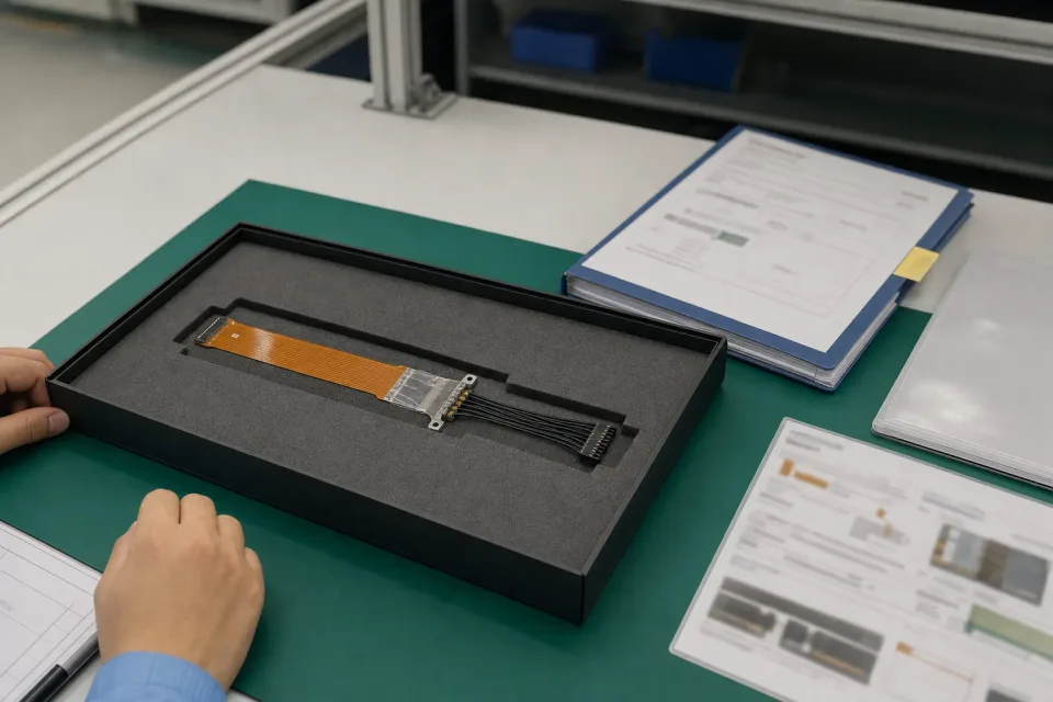
Controlled-document and transition-zone sample-approval bench for an FPC-to-wire hybrid program, hybrid sample in foam tray with FPC end, wire end, and reinforced transition visible
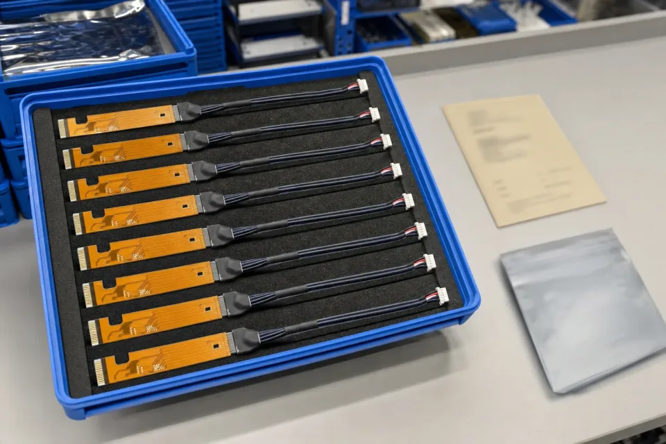
Lot tray of finished FPC-to-wire hybrid harnesses with batch identification and protective packaging
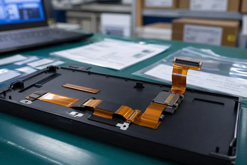
FFC and FPC sample approval archive with protected FPC sample and label props
FFC and FPC revision traceability record with cable set, connector lot cards, and folder sleeves
FAQ
What makes FPC-to-wire hybrid work different from normal FFC / FPC?
The risk is concentrated in the transition from FPC pad to discrete wire, so pad design, termination method, reinforcement, strain relief, and inspection criteria need a combined review.
Can you start from an old hybrid sample?
Yes. Old samples help, but pad geometry, wire gauge, transition method, and active device version still need to be confirmed before release.
What information is needed for a quote?
Send the FPC drawing, pad details, wire gauge, route path, reinforcement expectations, old sample photos if available, quantity, and timing.
Can the joint be reinforced?
Often yes, but the reinforcement method depends on pad layout, wire exit, bend zone, material compatibility, and installed space.
What records can support repeat orders?
Drawing revision, process notes, sample approval, inspection records, batch labels, and shipment documents can be linked to the released scope.