Technical Reference · COMPACT-DEVICES
Compact-Device Flexible Interconnect
Custom FFC / FPC Assemblies for Compact Devices
For small electronics, dense internal layouts, and tighter connector-fit judgement
EDPcable supports custom FFC and FPC assemblies for compact devices, display modules, and other products where connector fit, route geometry, reinforcement, and local space matter more than a simple flexible connection. The practical challenge is rarely whether one sample can be made. It is whether pitch, connector direction, reinforcement, and revision scope all match the current product under one released definition.
Quick Links
QUICK ACCESSStart with the sections closest to the project structure, interface requirements, and validation scope.
Compact-Device FFC / FPC Product Overview
Compact-device FFC and FPC programs work best when the product context is already clear and the next review can focus on connector fit, route path, reinforcement, local space, and revision control before sampling.
| NO | Item | Typical Range or Meaning |
|---|---|---|
| 01 | Typical Use | Small electronics, display modules, dense internal links, compact consumer hardware |
| 02 | Key Inputs | Pitch, connector references, route path, reinforcement details, revision scope |
| 03 | Engineering Focus | Connector fit, compact-route validity, reinforcement positions, local enclosure limits |
| 04 | Quality Focus | Stable route execution, repeatable connector fit, revision-linked records |
| 05 | Release Basis | Connector path, route notes, reinforcement details, and file-controlled revision scope |
Customer Pain Points
Compact-device FFC and FPC projects often sound simple because the product is small. In real RFQ and sample work, the bigger delays usually come from connector fit, route geometry, reinforcement, and local enclosure limits rather than from the flexible-cable label alone.
| NO | Customer Pain Point | Typical Risk | What Needs Early Confirmation |
|---|---|---|---|
| 01 | Product design issues | The connector set, route path, or reinforcement still does not truly fit the device structure, so the sample becomes only a temporary reference | Connector references, route path, reinforcement, and local enclosure space |
| 02 | Product quality issues | Route execution, connector fit, or reinforcement consistency drifts across batches | Structure definition, quality focus, and revision linkage |
| 03 | Lead-time issues | Missing compact-layout inputs force repeated sample loops and delay release | Connector data, route notes, project stage, and quantity |
| 04 | After-sales issues | It becomes difficult to tell whether the issue came from route fit, revision, or local assembly conditions | Drawing files, sample approval records, batch labels, and shipment records |
| 05 | Complaint-handling issues | Revision boundaries are unclear, so issue tracing stays slow | Revision confirmation, batch correspondence, and inspection records |
| 06 | Pricing issues | A broad flexible-interconnect request turns into repeated pricing changes once real fit constraints surface | Structure complexity, material expectations, quantity, and timing |
Product Applications
Compact-device FFC and FPC is not only a cable type. It usually appears in products where route density, connector fit, reinforcement, and enclosure-space judgement all matter. The five scenes below are the most common application contexts.
| NO | Application Scene | Scene Focus | Typical Concerns |
|---|---|---|---|
| 01 | Handheld terminals | The enclosure is tighter and the route is shorter | Connector direction, reinforcement, assembly efficiency |
| 02 | Portable consumer devices | Revision rhythm is faster and delivery timing matters more | Structure boundaries, lead time, batch consistency |
| 03 | Small display modules | Connector space stays more sensitive | Route path, fixing points, pitch fit |
| 04 | Wearable devices | The structure is more flexible and more constrained | Bend zones, reinforcement, stability |
| 05 | Miniature control modules | Batch rhythm stays more flexible | Sample speed, file correspondence, after-sales traceability |
Application Scene Visuals
IMAGES · 05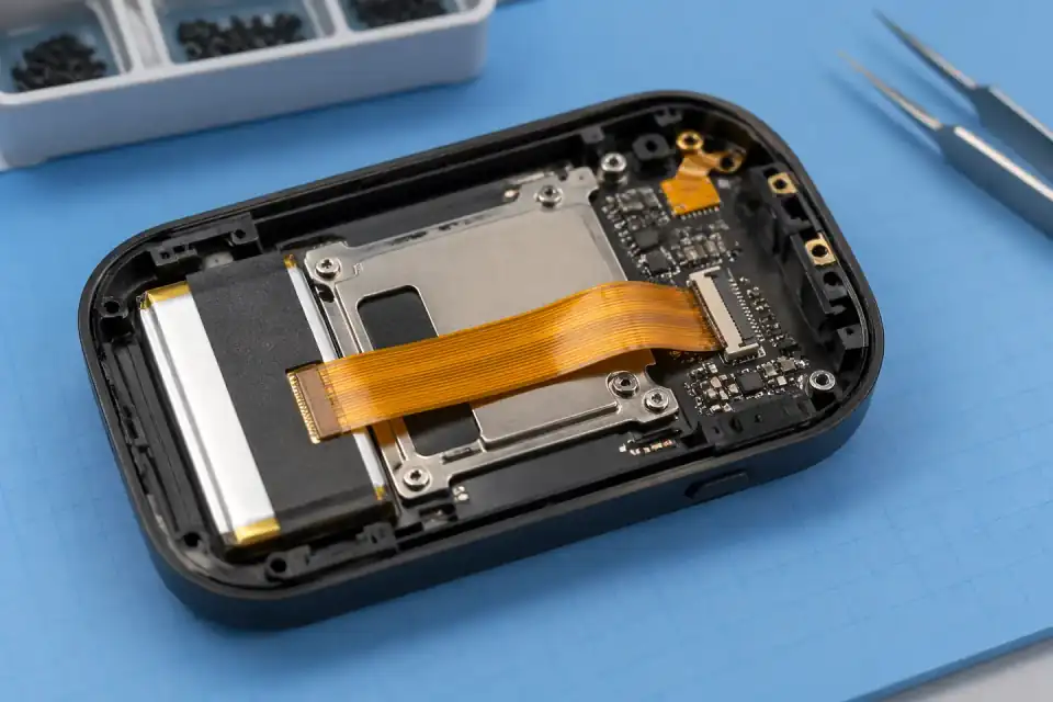
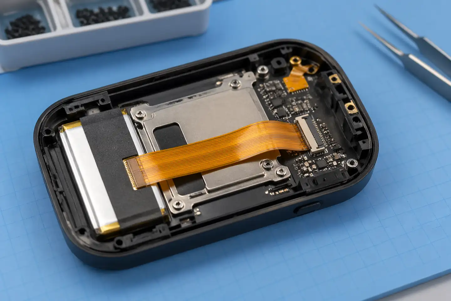
FFC and FPC assembly inside a handheld terminal device
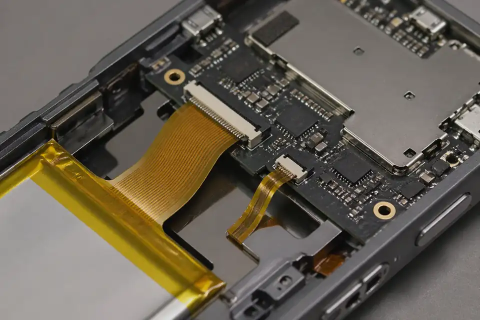
FFC and FPC assembly inside a portable consumer device
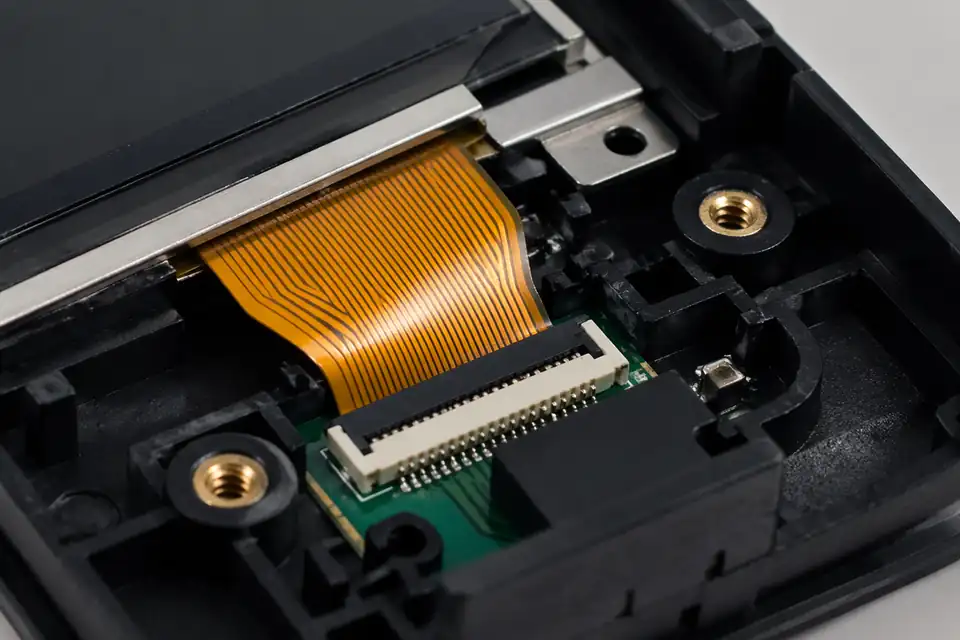
FFC and FPC assembly inside a small display module
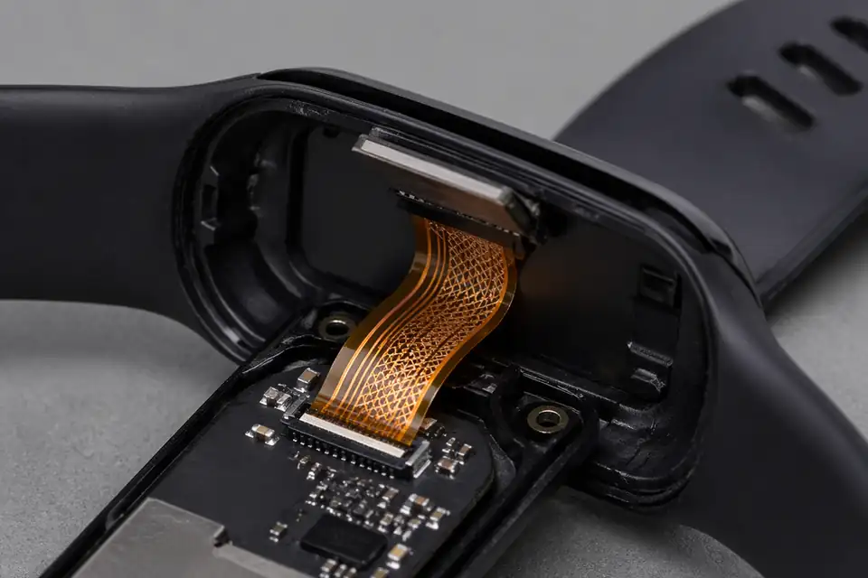
FFC and FPC assembly inside a wearable device
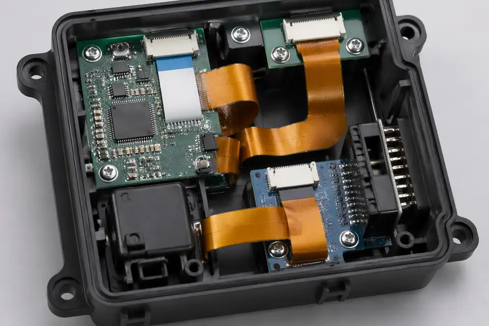
FFC and FPC assembly inside a mini control module
Compact Device Packaging Matrix
Compact-device routing is a packaging problem shared by the cable, connectors, enclosure, and assembly sequence. The release must show where the flexible link sits at every installation step, including temporary handling positions before the housing is closed.
| NO | Packaging factor | Definition question | Release artifact |
|---|---|---|---|
| 01 | Available envelope | What volume is available in open and closed assembly states? | Section views and keep-out model |
| 02 | Connector access | Can the tail be inserted, locked, and inspected with production tools? | Assembly-access study |
| 03 | Cable construction | Does FFC or FPC better fit the route, shielding, and reinforcement needs? | Approved construction and BOM |
| 04 | First bend | Where may the route turn after leaving each connector? | Straight-entry and bend-zone dimensions |
| 05 | Assembly sequence | Which components are fitted before and after the cable? | Numbered work sequence |
| 06 | Fixing method | How is the route retained without pressure on conductors or contacts? | Tape, guide, or clip detail |
| 07 | Electrical loading | Which conductors carry signal, ground, or power and at what project limit? | Netlist and load allocation |
| 08 | Service boundary | Is the cable replaceable, and what handling is allowed? | Service instruction or non-serviceable note |
First-Party Engineering References
- Molex FFC/FPC connector portfolio
Use to compare available connector form factors and selection fields at portfolio level; enclosure fit and exact ratings require the selected product data.
- TE FFC, FPC and ribbon connectors
Use for TE connector categories and intended interconnect contexts, not as evidence for a completed compact-device assembly.
Compact Packaging Failure Review
Most compact-device failures are introduced during assembly or housing closure. The review follows the cable through insertion, temporary folding, fastening, and final compression to find loads that are absent in the free-state drawing.
| NO | Failure mode | Packaging trigger | Mitigation |
|---|---|---|---|
| 01 | Housing pinch | The route crosses a seam, boss, screw, or snap feature | Add verified clearance and route retention |
| 02 | Incomplete connector lock | Tool or finger access is blocked after nearby parts are installed | Sequence assembly to preserve insertion and inspection access |
| 03 | Tail buckling | The first bend pushes the cable back toward the connector | Increase straight lead-in and remove compressive preload |
| 04 | Abrasion during closure | A cover drags the cable across a sharp or rough feature | Control surfaces and observe the actual closing motion |
| 05 | Localized heating | Power allocation and restricted airflow raise conductor temperature | Validate loading in the installed thermal condition |
| 06 | Service damage | Disassembly pulls the route before the connector is released | Provide access order and handling points |
Compact Assembly Verification Plan
A golden sample in the open state is useful, but verification must also inspect concealed areas after the housing is closed. Representative hardware, fasteners, adhesives, and production tools are included so the trial reflects the actual load path.
| NO | Verification | Test approach | Required result |
|---|---|---|---|
| 01 | Digital clearance review | Overlay route and tolerances against enclosure features | No predicted collision or cable entrapment |
| 02 | Production-sequence trial | Build representative units in the intended order | Operators can insert, lock, and inspect each end |
| 03 | Closed-housing teardown | Open completed samples and inspect hidden contact areas | No pinch marks, scoring, or displaced retention |
| 04 | Electrical continuity | Test before installation and after housing closure | Unchanged point-to-point result |
| 05 | Loaded temperature check | Operate specified power circuits in representative packaging | Project-defined temperature-rise limit |
| 06 | Handling simulation | Apply approved assembly and service manipulations | No connector release or route damage |
| 07 | First-article record | Capture route images, component revisions, and test outcomes | Traceable approval for production configuration |
Engineering Capability
Engineering value in a compact-device page comes from tying pitch, connector fit, route geometry, and reinforcement together before release. Cross-family engineering review, drawing control, and documentation practice are covered in the Related Capability Pages below.
Engineering Capability
Review pitch, connector references, route path, and reinforcement details as one engineering problem.
Treat compact-space limits and first-turn behaviour as part of the same release definition.
Quality and Verification Highlights
Focus on repeatable route execution and stable connector fit.
Watch bend transitions, reinforcement areas, and local-fit zones closely in compact builds.
Evidence Chain
Sample Approval and Fit-Review Records
Use sample confirmation records and route-review notes to show whether the approved sample actually matches the route, reinforcement, and local-fit conditions being quoted.
Compact-Device Fit and Release Records
For a compact enclosure, traceability is useful only when connector revisions, stack limits, insertion direction, and the approved installed route remain tied to the same build definition.
Enclosure-interface release drawing
Freeze connector suffixes, contact orientation, cable outline, stiffener details, first-exit direction, and local keep-outs against the intended enclosure revision.
Installed-fit sample record
Use the approved sample, fit photos, or customer fixture result to confirm insertion access, housing clearance, and strain-free routing before release.
Variant identification
Keep labels and order records specific to connector revision, contact side, stiffener, and route length so visually similar compact-device variants stay separated.
Thin-tail shipment protection
Choose packaging that supports the flexible tail and connector ends without adding unintended bends or pressure at the exposed-contact region.
Certifications / Records Visuals
IMAGES · 04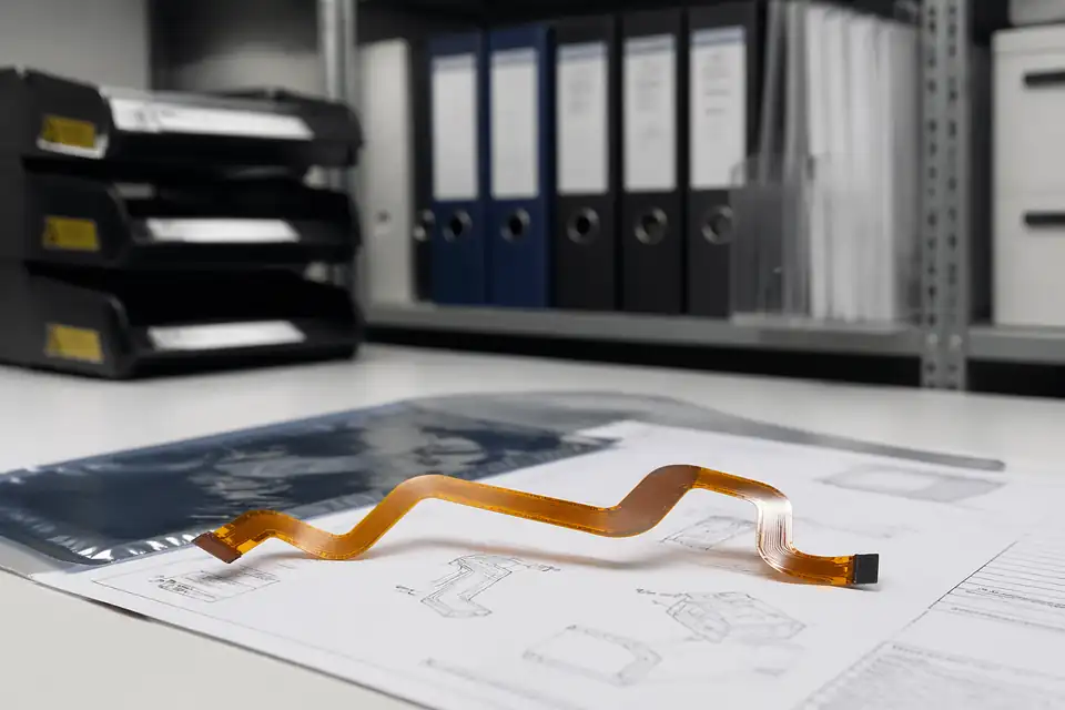
FFC and FPC document-control scene with release files secondary to the flexible assembly
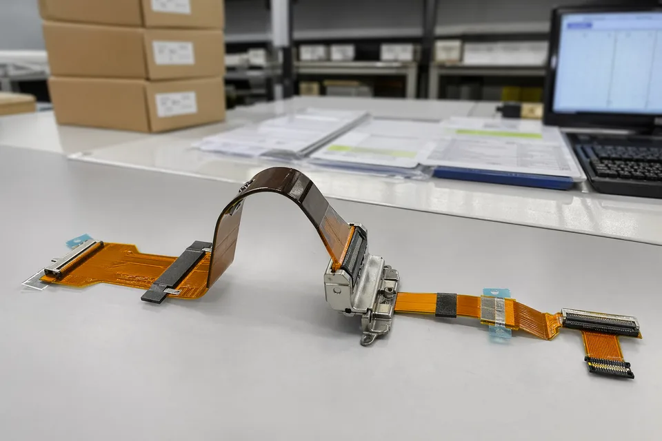
FFC and FPC controlled release record scene with flexible assembly sample foreground
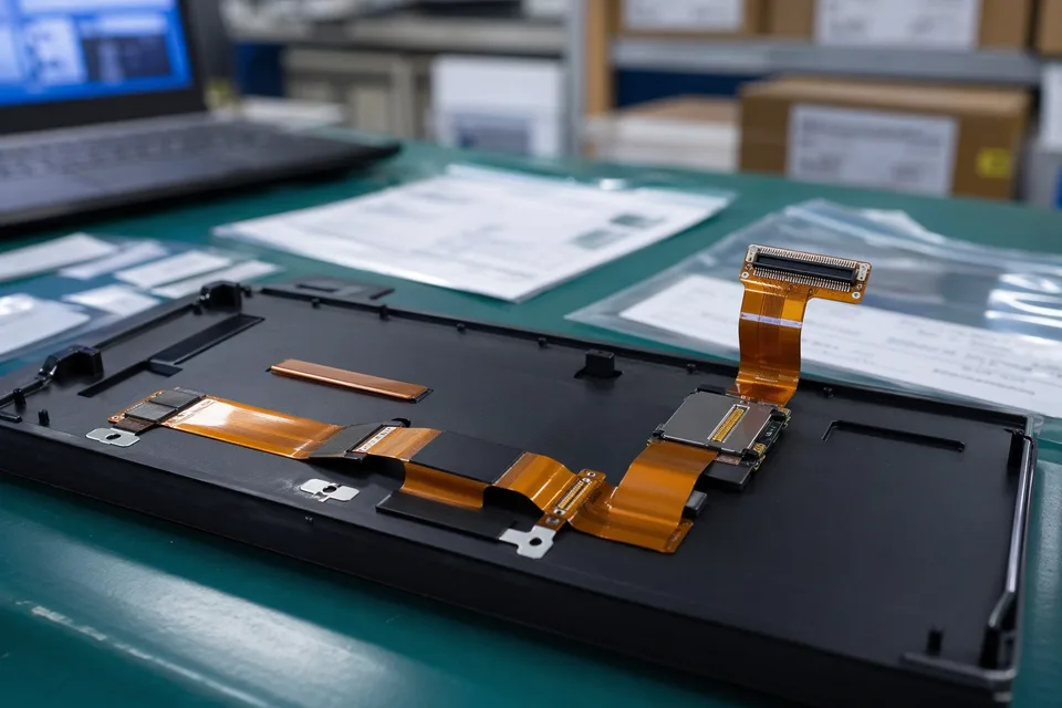
FFC and FPC sample approval archive with protected FPC sample and label props
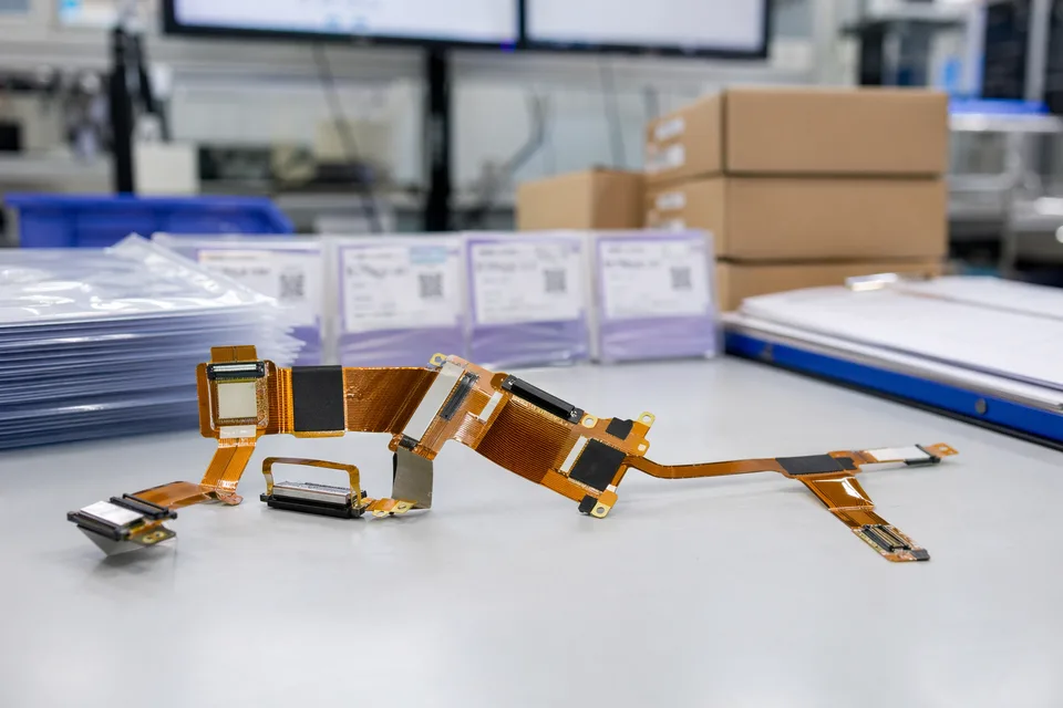
FFC and FPC revision traceability record with cable set, connector lot cards, and folder sleeves
FAQ
Can you review a compact-device project from an old sample?
Yes. Old samples help, but the current route path, connector fit, reinforcement, and revision scope still need to be checked before the sample can represent the released build.
What is the minimum input for a compact-device quotation?
Send connector references, route notes, reinforcement details, project stage, and expected quantity together with any pitch information.
Why do compact-device flexible routes need more than the connector reference?
Because route geometry, local enclosure fit, reinforcement, and release boundaries often decide whether the assembly can actually be released cleanly.
Can one compact-device route serve several product variants?
Sometimes, but only if route geometry, connector fit, reinforcement, and revision boundaries stay inside the same approved definition.
Can review start before the full drawing package is complete?
Yes. Endpoint drawings, the insertion sequence, housing clearances, temporary folds, and retention points are enough to review compact-device packaging before the enclosure release is complete.