Technical Reference · FINE-PITCH
Fine-Pitch Flexible Interconnect
Custom Fine-Pitch FFC / FPC Assemblies
For compact devices, dense connectors, and flexible routes that need cleaner fit and release control
EDPcable supports custom fine-pitch FFC and FPC assemblies when connector density and the interface tolerance stack still drive pitch selection. Review the mating-connector drawing, conductor count, contact orientation, exposed-contact geometry, stiffener, and route clearance together. RFQs already fixed at 0.5mm or 1.0mm follow the pitch-specific path; this direction covers density-led selection and other project-defined fine-pitch interfaces.
Quick Links
QUICK ACCESSStart with the sections closest to the project structure, interface requirements, and validation scope.
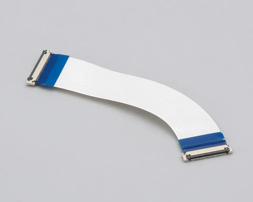
Fine-Pitch FFC / FPC Product Overview
Use this direction while connector density, pitch selection, or interface tolerance is still under review. Once 0.5mm or 1.0mm is fixed, the pitch-specific route provides the narrower RFQ checklist.
| NO | Item | Typical Range or Meaning |
|---|---|---|
| 01 | Typical Direction | Project-defined fine-pitch interfaces where density or pitch selection is not yet closed |
| 02 | Common Programs | Display modules, compact consumer devices, ZIF-linked systems, dense internal flexible routes |
| 03 | Key Inputs | Pitch, connector family, reinforcement notes, route path, revision scope |
| 04 | Engineering Focus | Pitch execution, connector fit, bend zones, reinforcement, installation space |
| 05 | Release Basis | Connector references, route notes, reinforcement details, and revision-controlled records |
Engineering Inputs
Use these items as first-round review inputs so the discussion does not rely on the page label alone.
Send connector references or clear mating photos.
Include pitch notes, route path, and the key bend or fixing zones.
Add reinforcement notes and local enclosure constraints.
Describe project stage, expected quantity, and timing target.
Explain any variant boundaries that affect the route.
Customer Pain Points
Fine-pitch FFC and FPC work often looks highly specific because the pitch category is already known. In real RFQ and sample work, delays usually appear in connector matching, reinforcement, route geometry, and revision scope rather than in the pitch label alone.
| NO | Customer Pain Point | Typical Risk | What Needs Early Confirmation |
|---|---|---|---|
| 01 | Product design issues | Pitch, connector family, or route geometry still do not truly match the device structure, so the sample becomes only a temporary reference | Pitch definition, connector references, route path, reinforcement, and installation space |
| 02 | Product quality issues | Termination, flexible-route execution, or local-fit consistency drifts across batches | Structure definition, quality focus, and revision linkage |
| 03 | Lead-time issues | Missing fit and reinforcement inputs force repeated sample loops and delay release | Connector data, route path, reinforcement notes, project stage, and quantity |
| 04 | After-sales issues | It becomes difficult to tell whether the issue came from pitch execution, structure, revision, or installation conditions | Drawing files, sample approval records, batch labels, and shipment records |
| 05 | Complaint-handling issues | Revision boundaries are unclear, so issue tracing stays slow | Revision confirmation, batch correspondence, and inspection records |
| 06 | Pricing issues | A broad flexible-interconnect request turns into repeated pricing changes once real fit constraints surface | Structure complexity, material expectations, quantity, and timing |
Product Applications
Fine-pitch FFC and FPC is not only a specification label. It usually appears in device programs where connector density, route geometry, reinforcement, and local-fit judgement all matter. The five scenes below are the most common application contexts.
| NO | Application Scene | Scene Focus | Typical Concerns |
|---|---|---|---|
| 01 | Display-module fine-pitch links | Connector density is higher | Pitch, connector fit, route space |
| 02 | Compact consumer devices | The enclosure is thinner and assembly rhythm is faster | First route turn, reinforcement positions, revision boundaries |
| 03 | ZIF-linked systems | Connector engagement matters more | Pitch, insertion fit, release logic |
| 04 | Wearable devices | Miniaturisation is stronger | Flexible route stability, reinforcement, local space |
| 05 | Small-module interconnect work | Batch rhythm stays more flexible | Sample timing, records, and after-sales traceability |
Application Scene Visuals
IMAGES · 05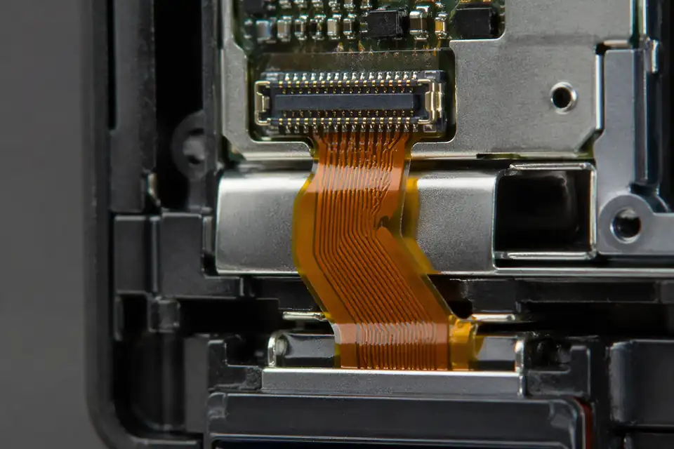
Fine-pitch FFC and FPC assembly in a compact display-module connection
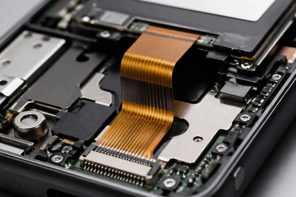
Fine-pitch FFC and FPC assembly inside compact consumer electronics with thin-space routing
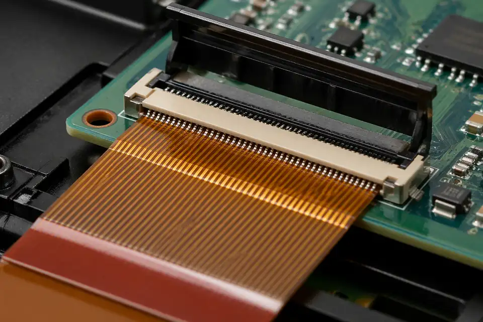
Fine-pitch FFC and FPC assembly in a ZIF-connected electronics project
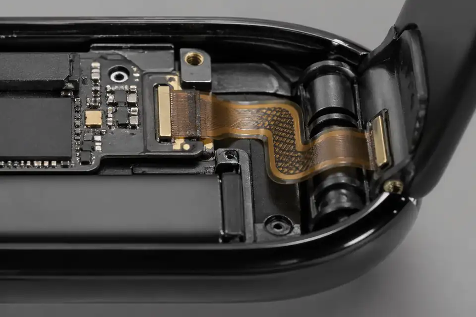
Fine-pitch FFC and FPC assembly inside a wearable device
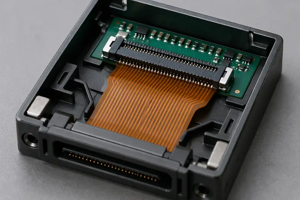
Fine-pitch FFC and FPC assembly inside a small interconnect module
Fine-Pitch Interface Definition
A fine-pitch release starts with the exact mating interface, not a nominal pitch alone. The connector drawing, exposed-contact geometry, reinforcement, route envelope, and electrical allocation must resolve to one buildable revision before tooling or samples are approved.
| NO | Definition item | Decision required | Release evidence |
|---|---|---|---|
| 01 | Mating connector | Record manufacturer, series, exact part number, and contact position | Controlled connector drawing or customer specification |
| 02 | Pitch and conductor count | Match the cable pattern to the selected mating part | Dimensioned contact pattern |
| 03 | Contact orientation | Define the exposed-contact face at each cable end from an explicitly named viewing direction | End-view detail with Pin 1 |
| 04 | Exposed-contact geometry | Set exposed length, width, edge clearance, and insertion datum | Dimensioned tail detail |
| 05 | Stiffener system | Specify material, thickness, length, adhesion area, and datum | Stack-up and tolerance note |
| 06 | Cable construction | State FFC or FPC structure, conductor arrangement, dielectric, and shielding when used | Approved material and layer definition |
| 07 | Route controls | Mark static bends, keep-outs, clamp zones, and first-turn clearance | Installed-route drawing |
| 08 | Electrical allocation | Separate signal, ground, and power conductors using project limits | Released netlist and load table |
First-Party Engineering References
- Molex FFC/FPC connector portfolio
Use for portfolio-level selection fields such as pitch, circuit count, actuator style, orientation, and contact side; confirm every value on the chosen part drawing.
- Hirose FH12 series
Use only for FH12-series features and published series ranges; it does not define unrelated fine-pitch interfaces or completed cable performance.
Fine-Pitch Failure Mode Review
Fine-pitch defects often remain hidden until insertion because several small tolerances accumulate at the cable tail. The review therefore follows the contact pattern through handling, connector entry, retention, and the first constrained bend.
| NO | Failure mode | Likely mechanism | Preventive control |
|---|---|---|---|
| 01 | Partial insertion | Tail thickness, stiffener, or insertion datum does not match the connector | Verify the complete tail stack against the exact mating drawing |
| 02 | Contact-side reversal | Top and bottom views were mixed between drawing and assembly | Use a keyed end view with Pin 1 and exposed-contact side |
| 03 | Adjacent conductor short | Tail registration or exposed copper geometry drifts | Control artwork, trimming, and optical inspection criteria |
| 04 | Intermittent open | Local crease or conductor damage forms near the stiffener edge | Keep the first bend outside the protected transition zone |
| 05 | Retention variation | Stiffener thickness or adhesive build changes insertion force | Qualify the stack and monitor critical incoming dimensions |
| 06 | Contact contamination | Handling residue reaches the exposed mating area | Define clean handling, protection, and visual rejection limits |
Fine-Pitch Release Verification
Verification links dimensions to actual mating behavior. Measurements are taken from controlled datums, while fit and electrical checks use the intended connector or an approved equivalent fixture defined by the project.
| NO | Verification | Method | Acceptance basis |
|---|---|---|---|
| 01 | Drawing reconciliation | Independent comparison of cable tail, connector drawing, and netlist | No unresolved dimensional or orientation conflict |
| 02 | Tail dimensional inspection | Measure pitch, width, exposure, stiffener, and critical thickness | Released drawing tolerances |
| 03 | Mating trial | Insert representative samples into the specified connector or approved fixture | Full seating without visible tail damage |
| 04 | Continuity test | Test every assigned conductor against the released netlist | Correct point-to-point result |
| 05 | Isolation check | Test adjacent or specified isolated nets where required | Project-defined electrical limit |
| 06 | Retention assessment | Evaluate cable retention with the selected connector closed | Connector and project acceptance criteria |
| 07 | First-article review | Record dimensions, images, material lot, and test result | Approved, revision-linked inspection package |
Engineering Capability
Engineering value in a fine-pitch FFC / FPC page comes from tying pitch execution, connector fit, route geometry, and reinforcement notes together before release. Cross-family engineering review, drawing control, and documentation practice are covered in the Related Capability Pages below.
Engineering Capability
Review pitch, connector references, route path, and reinforcement notes as one engineering problem.
Treat bend zones and reinforcement positions as part of the same release definition.
Quality and Verification Highlights
Focus on repeatable route execution and stable connector fit.
Watch bend transitions, reinforcement areas, and connector tails closely in compact builds.
Evidence Chain
Sample Approval and Fit-Review Records
Use sample confirmation records and fit-review notes to show whether the approved sample actually matches the route, reinforcement, and local-fit conditions being quoted.
Fine-Pitch Release Files and Traceability
For fine-pitch FFC/FPC work, the useful records lock contact geometry, stiffener definition, contact orientation, and inspection criteria to the released connector interface.
Interface drawing and revision record
State conductor count, pitch, exposed-contact length, contact side, cable thickness, and stiffener details on the released drawing so sourcing and assembly use one interface definition.
Sample fit and termination review
Keep the mating connector reference, sample-fit result, conductor-registration check, and exposed-contact inspection with the approved sample basis.
Lot and shipment identification
Use the released part number and revision on labels and shipment records so fine-pitch variants with different contact sides or stiffeners are not mixed.
Contact-area packaging controls
Define packaging that protects exposed contacts and stiffened ends from creasing, abrasion, and contamination during storage and shipment.
Certifications / Records Visuals
IMAGES · 04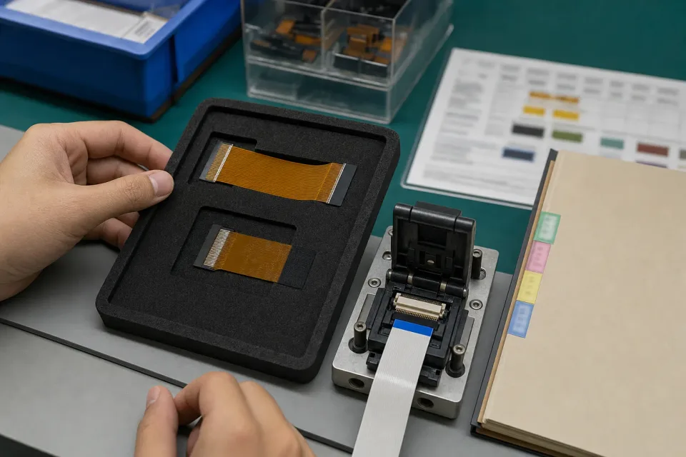
Fine-pitch FFC and FPC sample-approval bench with reinforcement films, ZIF mating fixture, and pitch reference
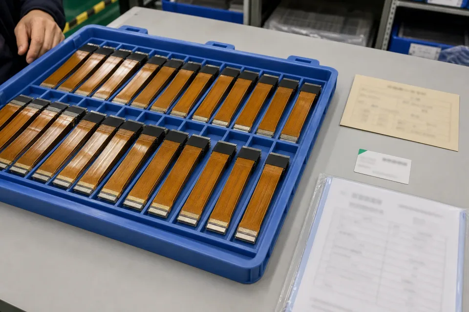
Lot tray of fine-pitch FFC and FPC samples showing consistent reinforcement, contact orientation, revision identification, and fit-check records
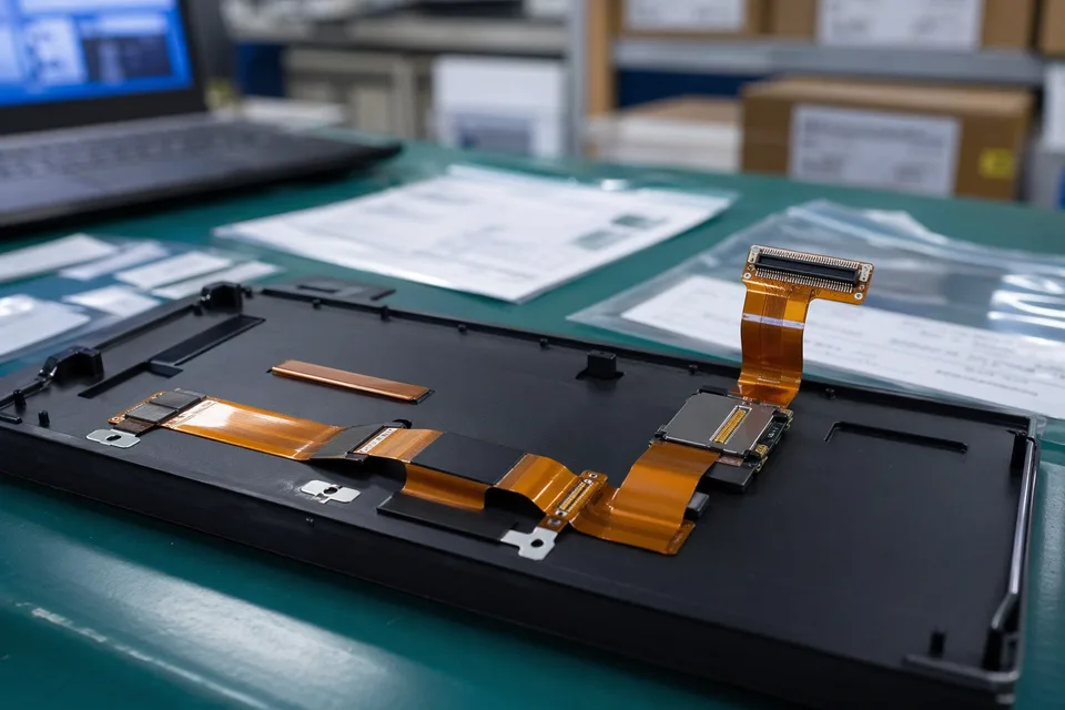
FFC and FPC sample approval archive with protected FPC sample and label props
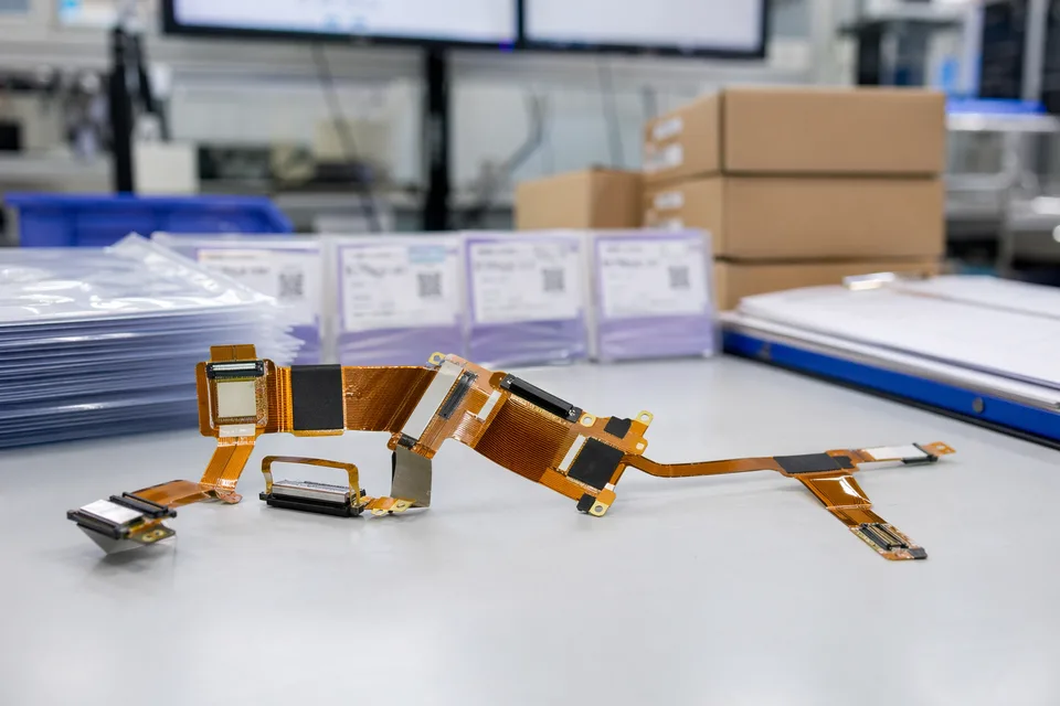
FFC and FPC revision traceability record with cable set, connector lot cards, and folder sleeves
FAQ
Can you review a fine-pitch FFC / FPC project from an old sample?
Yes. Old samples help, but the current pitch fit, connector family, route path, and reinforcement logic still need to be checked before the sample can represent the released build.
What is the minimum input for a fine-pitch quotation?
Send connector references, pitch notes, route context, reinforcement details, project stage, and expected quantity.
Why do fine-pitch flexible-interconnect programs need more than the pitch value?
Because connector fit, route geometry, reinforcement, and local enclosure limits often decide whether the assembly can actually be released cleanly.
Can one fine-pitch cable serve several product variants?
Sometimes, but only if connector fit, route geometry, reinforcement, and revision boundaries stay inside the same approved definition.
Can review start before the full drawing package is complete?
Yes. The exact connector drawing, contact face, tail thickness, stiffener, and first-bend envelope support an early fine-pitch review before every enclosure dimension is final.