Technical Reference · 30-PIN
30-Pin Internal Display Interconnect
30-Pin eDP Harnesses Defined by the Exact Panel Interface
Use this path only after the panel and source-board documents confirm a 30-position interface
A 30-position label narrows the sourcing path but does not define connector mating, pin assignment, lane population, power, or display capability. EDPcable releases each harness from the exact panel option, board connector, end-to-end net map, installed geometry, restraint points, and validation plan so the drawing, approved sample, and production build describe the same platform revision.
Quick Links
QUICK ACCESSStart with the sections closest to the project structure, interface requirements, and validation scope.
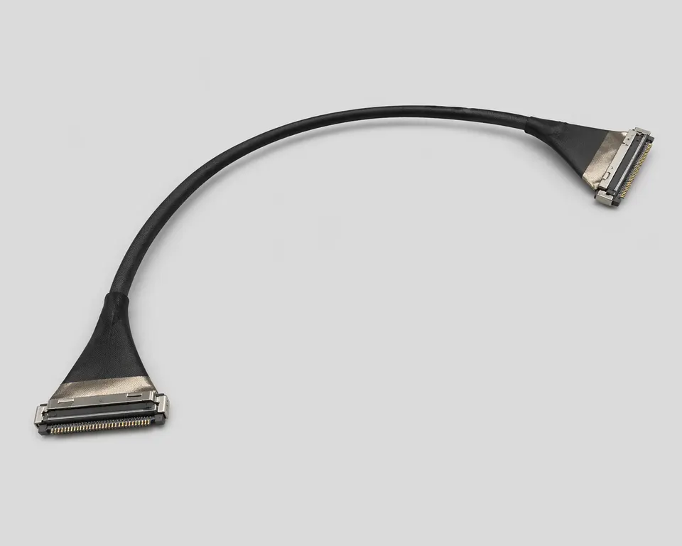
30-Pin Interface Release Inputs
Use this page when both endpoint documents already identify a 30-position path. The RFQ must still reconcile connector suffixes, contact views, every assigned net, route datums, bend zones, restraint, and the target-device test configuration.
| NO | Release field | Project definition |
|---|---|---|
| 01 | Interface Path | 30-position eDP path confirmed by the named panel and source-board revisions |
| 02 | Common Programs | Laptop, tablet, embedded display, compact industrial display, and HMI programs with released endpoint data |
| 03 | Connector Identity | Complete board-side and panel-side maker part numbers, suffixes, contact views, and mating orientation |
| 04 | Electrical Definition | End-to-end pin map, active and reserved contacts, lane allocation, power, AUX, control, grounds, and project target |
| 05 | Mechanical Definition | Datum-to-datum dimensions, connector exits, hinge or bend zones, fixing points, strain relief, and service clearance |
| 06 | Release Basis | Approved endpoint documents, controlled harness drawing, production-intent sample, and named device test plan |
Engineering Inputs
Use these items as first-round review inputs so the discussion does not rely on the page label alone.
Provide complete board-side and panel-side part numbers, suffixes, contact views, and the released pin map.
Provide datum-to-datum length and tolerance, connector exits, route, bend or hinge zones, fixing points, and strain relief.
State the panel, board, firmware, and device revisions covered by the request.
Define quantity by sample, pilot, and production stage plus the required delivery date.
Define continuity, fit, operational-link, and any signal-integrity method, limits, fixture, and report scope.
What 30 Positions Confirm - and What They Do Not
The position count is useful only as a first filter. A compatible harness still depends on the exact panel option, board connector, contact views, populated nets, power allocation, cable exits, and installed route. Treating any two 30-position parts as interchangeable is a common cause of no-display, damaged-power, and mechanical-fit failures.
| NO | Decision | What the 30-position label establishes | What still requires project evidence |
|---|---|---|---|
| 01 | Connector compatibility | The interface uses a 30-position path | Both complete connector codes, suffixes, keying, contact views, and mating orientation |
| 02 | Electrical compatibility | The request belongs in the 30-position review path | Every signal, power, AUX, control, ground, reserved contact, and lane assignment |
| 03 | Display capability | Nothing about resolution, refresh rate, touch, or backlight population | Panel option, source-board design, firmware configuration, and device validation |
| 04 | Mechanical fit | Only the connector position class | Datum length, exits, first bend, hinge motion, restraint, tape, clearance, and service route |
| 05 | Replacement release | That the old part appears to use 30 positions | Current endpoint revisions, an approved from-to map, installed comparison, and replacement test scope |
Release the Complete Endpoint Chain
Release begins by reconciling the panel document, source-board definition, and harness drawing. A sample can help identify an unknown part, but it cannot establish the current electrical or revision boundary by itself.
Validate the Installed Route, Not a Loose Cable
A bench continuity pass does not prove that a compact eDP harness will survive the real route. The production-intent sample should be checked in the released enclosure with the actual panel, source board, restraint, hinge or bend zones, and device test configuration.
| NO | Validation gate | Check | Release evidence |
|---|---|---|---|
| 01 | Endpoint review | Both connectors mate, orient, lock, and exit as shown | Part-number record, end views, and released from-to map |
| 02 | Installed fit | Datum length, first bend, hinge sweep, tape and restraint avoid connector-tail load | Installed photos or fit record against the released enclosure revision |
| 03 | Electrical release | Continuity follows the approved map with no opens, shorts, or unintended connections | Tester program revision and result tied to the harness revision |
| 04 | Device operation | The released panel and board combination starts and runs in the named configuration | Customer device test or agreed operational-link record |
| 05 | Change control | A panel, board, connector, pin-map, route, or firmware change triggers impact review | New revision decision and revalidation scope |
Installed Validation Evidence
IMAGES · 05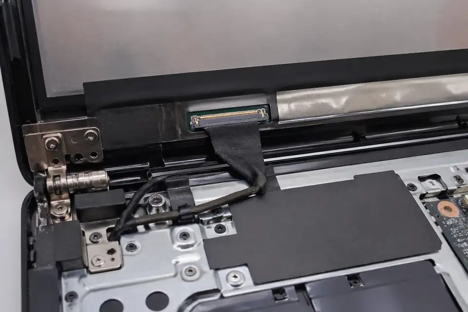
30-pin eDP path inside a compact laptop display hinge area
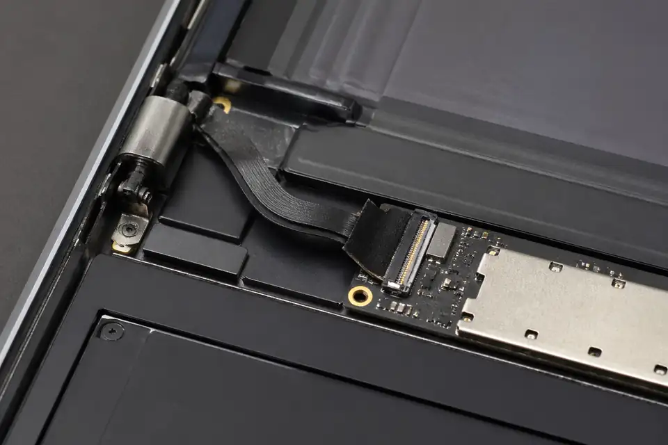
30-pin eDP installation inside a tablet or 2-in-1 device with thin-space routing
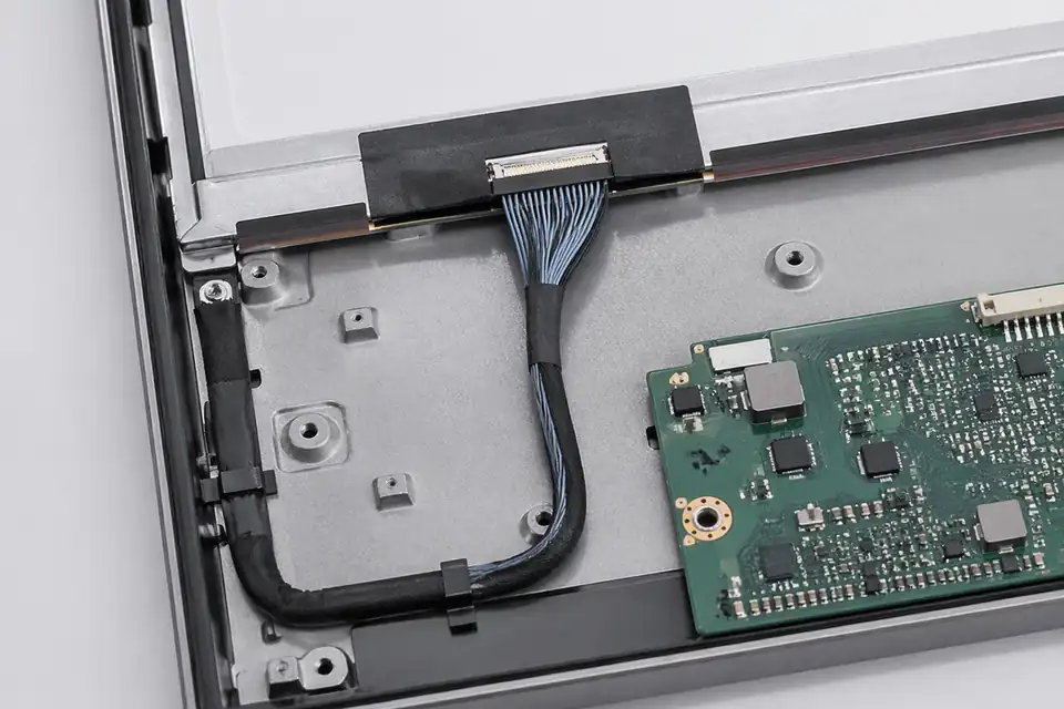
30-pin eDP route inside an embedded display module with edge routing visible
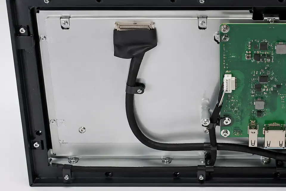
30-pin eDP assembly inside a compact industrial display with fixing-point context
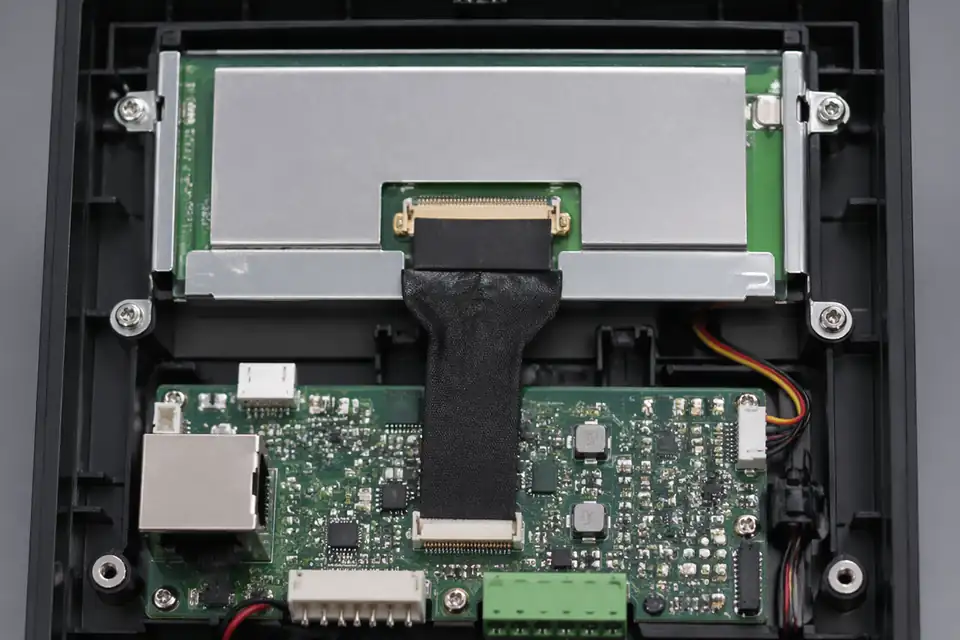
30-pin eDP path inside a small HMI terminal with tight-layout fit
Freeze the 30-pin Interface Before Routing
A 30-position label is only a starting point. Release should follow the exact panel drawing, source-board schematic, connector suffixes, mechanical stack, and approved BOM for the named platform.
| NO | Design decision | Required project input | Release condition |
|---|---|---|---|
| 01 | Panel-side interface | Panel connector maker and complete part number | Mating drawing and contact orientation agree |
| 02 | Board-side interface | Source-board connector and PCB datum | Pin-one view is unambiguous |
| 03 | Contact assignment | Panel pin table and board schematic | Power, AUX, ground, and main-link assignments match at both endpoints |
| 04 | Link architecture | Lane count, rate, color format, and panel revision | Timing, bits per pixel, lane count, link rate, and design margin are documented and approved |
| 05 | Finished geometry | Datum-to-datum length and controlled branch dimensions | Assembly fits the released device model |
| 06 | Cable construction | Approved conductor, insulation, shield, and drain BOM | Materials match the drawing revision |
| 07 | Mechanical restraint | Hinge zone, adhesive points, clips, and service access | No clamp loads a connector tail |
First-Party Engineering References
- VESA Embedded DisplayPort Standard 1.5 announcement
Protocol-generation context only; the applicable eDP revision and link settings remain platform inputs.
- I-PEX CABLINE-VS product documentation
First-party example of a 30-position connector option; use only when the BOM names the corresponding full parts.
30-pin Build Risks That a Pin Count Cannot Resolve
The review should trace each plausible defect to a drawing feature, process control, or device test instead of treating a successful bench connection as final evidence.
| NO | Failure mode | Likely mechanism | Required control |
|---|---|---|---|
| 01 | Connector will not mate | Wrong series, suffix, keying, or insertion direction | Approve both mating part numbers |
| 02 | Panel remains dark | Pin-map transposition or omitted control conductor | Compare net list at both ends |
| 03 | Intermittent image | Termination damage or an uncontrolled differential transition | Inspect preparation and validate the link |
| 04 | Hinge-related dropout | Harness length or restraint concentrates repeated motion | Relocate the flex zone from the termination |
| 05 | Radiated noise increase | Shield termination conflicts with the product grounding plan | Review chassis and circuit return paths |
Evidence Package for a 30-pin Release
Verification is complete when the approved drawing, inspected sample, and target device all represent the same panel, board, connector, and firmware configuration.
| NO | Verification | Method | Recorded acceptance |
|---|---|---|---|
| 01 | Definition audit | Cross-check BOM, schematic, panel sheet, and harness drawing | Signed revision comparison |
| 02 | Mating and fit | Install into the production-intent mechanical stack | No interference or partial lock |
| 03 | Continuity and isolation | Test every assigned net with approved limits | Serialized electrical result |
| 04 | Operational link | Run source-to-panel modes from the system test plan | Stable image and expected diagnostics |
| 05 | Signal-integrity validation | Test the exact assembly at the test points and operating mode named in the plan | Results meet the numeric limits in the cited test-plan revision |
| 06 | Pilot-lot workmanship audit | Audit terminations, dimensions, labels, and restraint features | Lot record tied to release drawing |
Engineering Capability
30-pin engineering review is strongest when connector references, route geometry, bend allowance, and fixing details are checked together before the sample is treated as a released definition. Cross-family drawing control and documentation practice are covered in the Related Capability Pages below.
Engineering Capability
Confirm connector references, pin definition, target length, route path, and fixing positions as one review package before sampling.
Review bend allowance, first-exit direction, and tape or retention points in the actual laptop, tablet, or compact-display layout.
Define when a 30-pin path can be shared across screen variants, and when connector, length, or route differences require a separate release.
Quality and Verification Highlights
Check termination consistency, connector tail handling, and route transitions that are easy to stress in compact 30-pin builds.
Keep sample approval, drawing notes, and inspection output tied to the same route and connector definition.
Watch bend zones, tape positions, and local protection details across repeat builds so the approved route is not only a one-off sample.
Evidence Chain
Connector and Pin-Definition Basis
Use connector references, mating photos, pin definition, and route notes to show which 30-pin structure is being quoted and sampled.
Sample Approval and Route-Fit Notes
Record whether the approved sample matches the bend zones, fixing points, and installation constraints in the actual device.
Revision and Batch Linkage
Tie drawing revision, sample approval, inspection output, and batch labels back to the same released 30-pin route definition.
Files and Batch Support
30-pin eDP work has its own document layer around route and fitting boundaries. Cross-family file control, batch traceability, and certification practice are summarised in the Related Capability Pages.
30-pin eDP route and fitting-boundary records
Capture the route path, local fit, and installation-space limits that are specific to the 30-pin eDP build so later structural differences can be traced back to the right layer of change.
Certifications / Records Visuals
IMAGES · 04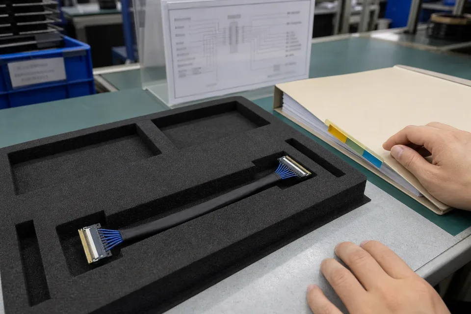
30-pin eDP sample-approval bench with a fine-pitch harness, pinout reference, and controlled drawing package
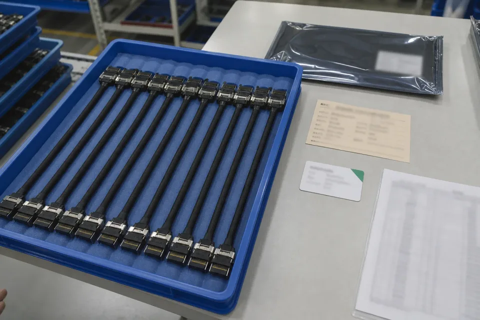
Lot tray of finished 30-pin eDP harnesses with revision identification and protective packaging
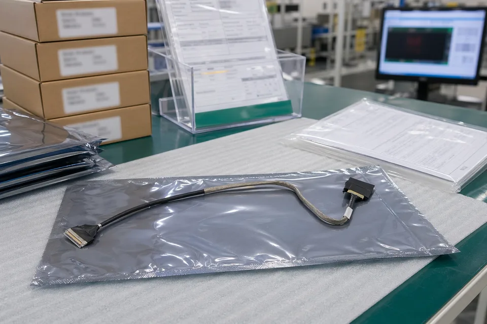
eDP revision traceability record with protected cable sample and controlled document sleeves
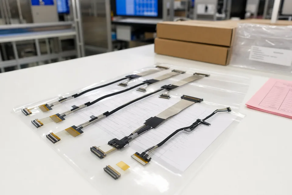
eDP batch release file scene with connector lot labels and display harness support context
FAQ
Can you build 30-pin eDP cables from samples or old parts?
Yes. Existing samples or legacy parts often make 30-pin review faster, but connector references, length, and installation conditions still need to be confirmed alongside them.
What is the minimum information needed for a 30-pin quotation?
At minimum, provide connector references or clear photos, pin definition, target length, installation conditions, project stage, and expected quantity.
Does 30-pin automatically mean an easier project than 40-pin?
Not necessarily. 30-pin projects are often more compact, and the real difficulty can still sit in bend space, route fit, and fixing details.
If one platform has multiple screen versions, can 30-pin cables be shared?
Possibly, but not from pin count alone. Connector family, pin definition, path, and fixing details all need to be checked together before shared use is assumed.
Can you still review the project if we only have one old harness and no full drawing?
Yes, but the old harness is usually only enough for an initial review. Add connector photos, length, installation context, and current device structure if you want the next step to be more accurate.