Technical Reference · 40-PIN
40-Pin Internal Display Interconnect
40-Pin eDP Harnesses with Controlled Power and Signal Mapping
Define every populated and reserved contact from the exact panel option and source-board revision
Forty contacts do not create a universal eDP pinout or performance class. EDPcable treats the panel option, source connector, lane allocation, power and return contacts, AUX and control functions, shielding, installed route, and product revision as one release package. That distinction matters when two 40-pin assemblies look similar but populate different electrical functions.
Quick Links
QUICK ACCESSStart with the sections closest to the project structure, interface requirements, and validation scope.
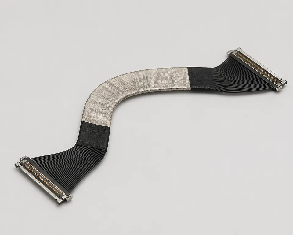
40-Pin Population and Release Inputs
Use this page after the exact panel option and board revision confirm a 40-position path. Before sampling, reconcile every contact, power budget, connector suffix, cable structure, shielding boundary, route, and device configuration.
| NO | Release field | Project definition |
|---|---|---|
| 01 | Interface Path | 40-position eDP path tied to one panel option and source-board revision |
| 02 | Common Programs | Laptop, industrial, medical, and other internal-display programs with released endpoint documentation |
| 03 | Connector Identity | Complete part numbers and suffixes at both ends, mating orientation, lock, contact views, and cable exit |
| 04 | Electrical Population | Active lanes, power and returns, AUX and controls, grounds, reserved contacts, rail load, and allowed voltage drop |
| 05 | Installed Structure | Cable construction, shielding and grounding, length stack, exits, bends, fixing, strain relief, and enclosure clearance |
| 06 | Release Basis | Approved documents, controlled drawing, production-intent sample, power-path review, and named device validation plan |
Engineering Inputs
Use these items as first-round review inputs so the discussion does not rely on the page label alone.
Provide full board-side and panel-side connector part numbers, suffixes, views, and the released 40-contact map.
Provide panel rail data, expected current, allowed voltage drop, and all power, return, AUX, control, and reserved assignments.
Provide finished dimensions, route, connector exits, bend zones, fixing, shielding, grounding, and strain relief.
State sample, pilot, and production quantities, target dates, and all platform revision boundaries.
Define continuity, thermal or voltage-drop, display-mode, EMI, and any signal-integrity test method and limits.
Customer Pain Points
A 40-pin label is only a sourcing entry point. The real release decision depends on the complete connector pair, pin assignment, cable structure, shielding requirements, installed route, and revision boundary for the target device.
| NO | Customer Pain Point | Typical Risk | What Needs Early Confirmation |
|---|---|---|---|
| 01 | Product design issues | The connector set, shielding stack, or route path does not truly match the device structure, so the sample becomes only a temporary reference | Connector references, route path, shielding conditions, and installation space |
| 02 | Product quality issues | Wire order, termination, shielding, or route execution drifts across batches | Released pin map, structure definition, quality focus, and revision linkage |
| 03 | Lead-time issues | Missing inputs cause repeated sample loops and slow down quotation, release, and production timing | Connector data, pin definition, installation boundaries, and project stage |
| 04 | After-sales issues | It becomes difficult to tell whether the issue came from structure, revision, shielding, or installation | Drawing files, sample approval records, batch labels, and shipment records |
| 05 | Complaint-handling issues | Revision scope stays unclear, so issue tracing remains slow | Revision confirmation, batch correspondence, and inspection records |
| 06 | Pricing issues | Blurred scope creates repeated pricing changes and weak cost control | Structure complexity, shielding expectations, quantity, and timing |
Product Applications
A 40-pin eDP assembly is valid only for the device interface and route defined by its connector pair, pin map, and released drawing. The scenes below show device-specific decisions to confirm rather than performance implied by pin count.
| NO | Application Scene | Scene Focus | Typical Concerns |
|---|---|---|---|
| 01 | Laptop display modules | Panel-specific connector and pin-map relationship | Bend zones, revision boundaries, shielding requirements, and connector matching |
| 02 | Medical display terminals | Released signal definition and file correspondence | Project-defined electrical checks, sample approval, and batch traceability |
| 03 | Industrial display modules | Enclosure-specific path and installation limits | Fixing points, EMI, structure protection |
| 04 | Portable display equipment | Local space and first-exit direction constrain the route | First-exit direction, tape positions, assembly efficiency |
| 05 | Other confirmed 40-pin internal-display systems | Connector, pin map, revision changes, and repeated batches all matter | Release scope, batch consistency, and lead-time coordination |
Application Scene Visuals
IMAGES · 05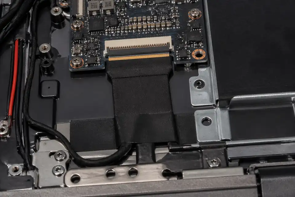
40-pin eDP path inside a high-resolution laptop display system
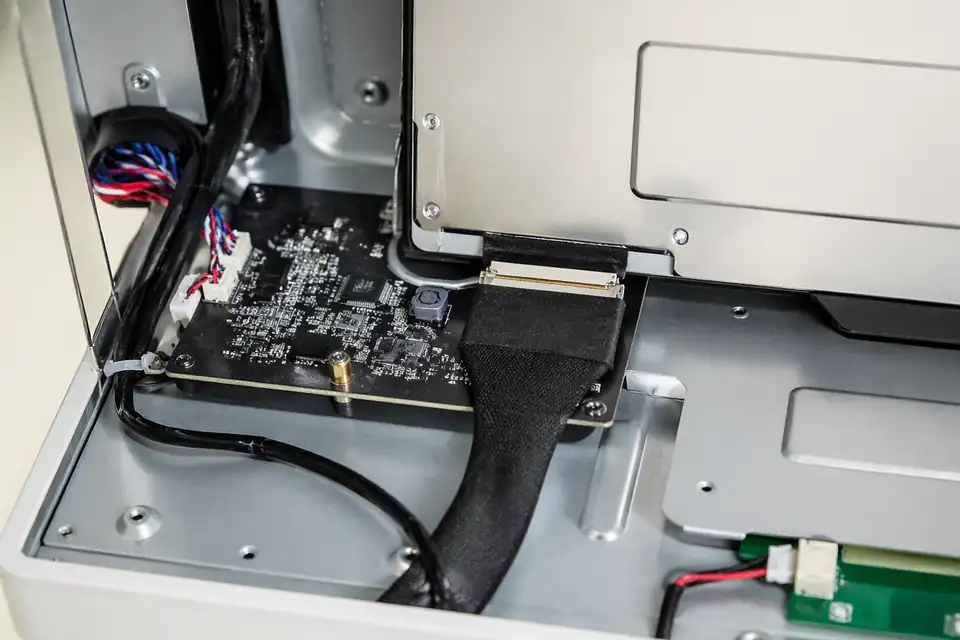
40-pin eDP route inside a medical display terminal with dense connector context
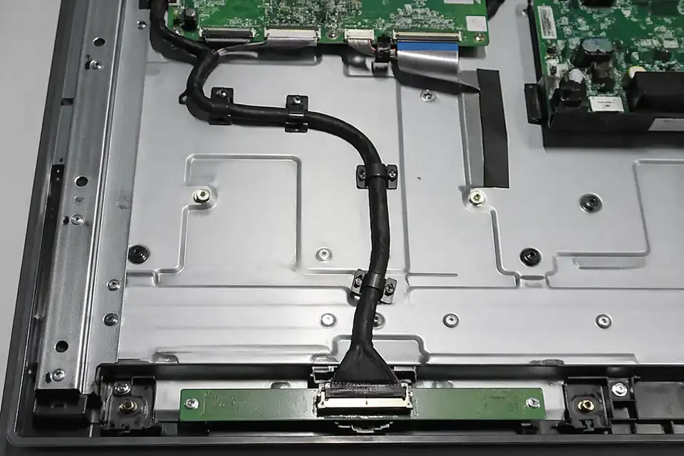
40-pin eDP assembly inside an industrial display module with longer routed path
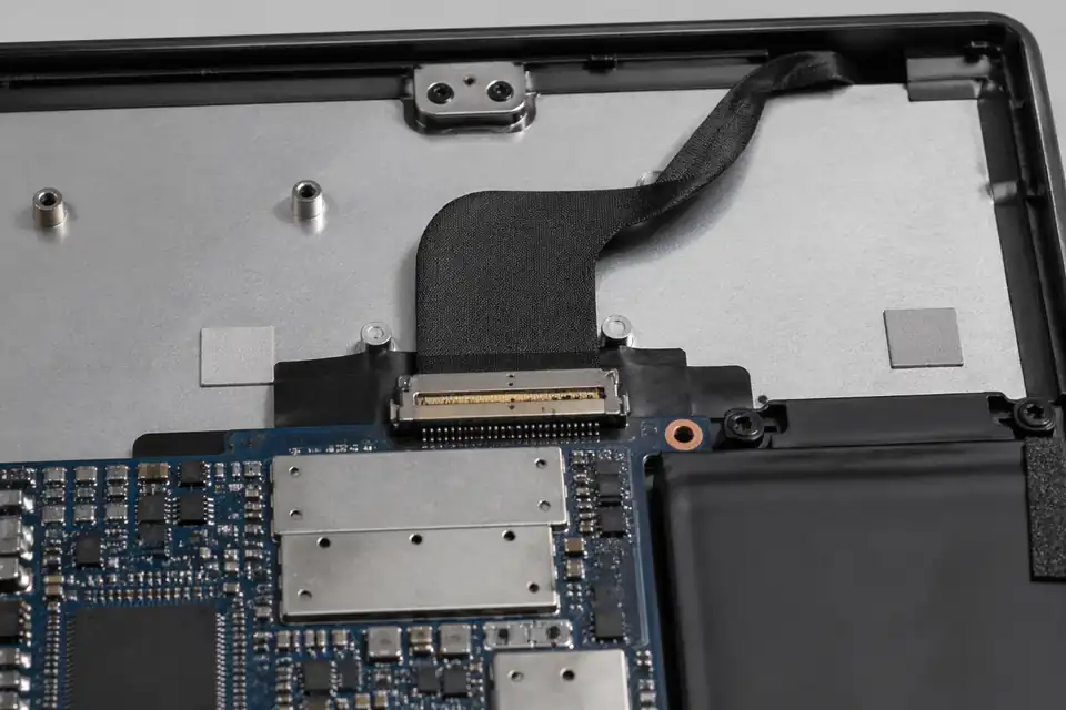
40-pin eDP installation inside a portable display device with space-constrained routing
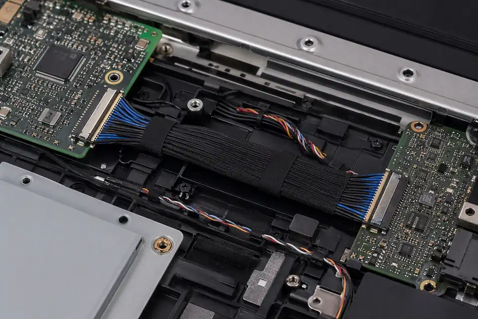
40-pin eDP harness inside a high-density internal display system with organized routing
Define the Complete 40-pin Electrical Population
Forty contacts do not prescribe a universal eDP pinout. Engineering must bind the harness to the actual panel option, board connector, populated functions, power budget, and released mechanical envelope.
| NO | Definition item | Authoritative input | Drawing requirement |
|---|---|---|---|
| 01 | Panel receptacle | Full maker part number with option suffix | Show datum, key, and mating face |
| 02 | Source connector | Board BOM and layout reference | State compatible plug and orientation |
| 03 | Forty-contact map | Panel datasheet matched to its exact option | Name every used and reserved position |
| 04 | Main-link allocation | GPU capability and required display timing | Record active lane groups and polarity |
| 05 | Power conductors | Panel rail current and allowed drop budget | Size conductors from the approved calculation |
| 06 | Auxiliary functions | Backlight, touch, or vendor-control definitions | Each power and control return maps to its intended circuit domain in the released pin list |
| 07 | Mechanical package | Length stack, exits, folds, and mounting hardware | Dimension all assembly-critical features |
First-Party Engineering References
- VESA Embedded DisplayPort Standard 1.5 announcement
Identifies the eDP standards lineage; it does not establish a universal 40-contact panel assignment.
- I-PEX CABLINE-VS product documentation
Manufacturer data for one 40-position-capable family, applicable only to selected CABLINE-VS part numbers.
Failure Review for Dense 40-contact Builds
Higher contact count adds opportunities for silent pin-definition and power-distribution errors, so the risk review should separate interface correctness from general workmanship.
| NO | Observed risk | Engineering cause | Prevention evidence |
|---|---|---|---|
| 01 | Incorrect panel option fitted | Shared base number hides a suffix difference | AVL includes the complete ordering code |
| 02 | Localized overheating at power or return contacts | Parallel power or return contacts were allocated incorrectly | Net allocation matches the rail analysis |
| 03 | Only some modes work | Lane population conflicts with requested timing | Mode matrix is reviewed before build |
| 04 | Touch or backlight fault | Auxiliary nets were inferred from another panel | Option-specific pin table controls assembly |
| 05 | Tail damage during closure | Connector exit collides with bezel or shield can | Released stack model includes the harness |
40-pin Qualification and Release Checks
The qualification unit must use production-intent contacts, shielding, fixtures, and device hardware; substitutions are documented rather than silently accepted.
| NO | Check | Execution | Acceptance basis |
|---|---|---|---|
| 01 | Pin-map reconciliation | Compare both connector views against system net names | Zero unresolved contact assignments |
| 02 | Power-path assessment | Measure rail drop and temperature in worst operating mode | Program-defined electrical and thermal limits |
| 03 | Connector engagement | Mate using the specified assembly sequence | Lock state visible and fully seated |
| 04 | Display mode sweep | Exercise every released resolution and refresh combination | No link or image anomaly |
| 05 | EMI evaluation | Test in the intended enclosure and grounding state | Acceptance criteria in the product compliance plan are met |
| 06 | Configuration trace | Capture panel, board, firmware, harness, and fixture revisions | Report identifies the tested build exactly |
Engineering Capability
The main engineering value in a 40-pin page is to confirm the exact connector, pin assignment, cable structure, and installed route before release. Cross-family engineering review, drawing control, and documentation practice are covered in the Related Capability Pages below.
Engineering Capability
Review shielding, length distribution, bend zones, and fixing details as one structure problem.
Confirm the complete connector references and pin definition before shielding or length choices are treated as stable.
Write revision boundaries early when several panel, display, or device versions may use similar 40-pin routes.
Quality and Verification Highlights
Focus on repeatable termination and shielding execution against the released 40-pin definition.
Watch connector tails, turn zones, and material transitions identified as critical in the installed route.
Keep inspection output tied to the released shielding, route, and connector definition so repeat batches do not drift from the approved sample.
Evidence Chain
Sample Approval and Shielding-Review Records
Use sample confirmation records and shielding-review notes to show whether the approved sample actually matches the route, bend zones, and installation conditions being quoted.
Connector and Pin-Definition Correspondence
Keep the selected 40-pin connector, mating reference, pin definition, and revision notes visible in the release basis for quotation and sampling.
Batch and Revision Traceability
Use batch labels, inspection output, and shipment-side records to connect later deliveries back to the same dense-route release definition.
Files and Batch Support
40-pin work has its own document layer around shielding and route boundaries. Cross-family file control, batch traceability, and certification practice are summarised in the Related Capability Pages.
Shielding and route-boundary records
Write the key route path, shielding structure, and installation-space limits clearly enough that later structural differences can be traced back to the right layer of change.
Certifications / Records Visuals
IMAGES · 04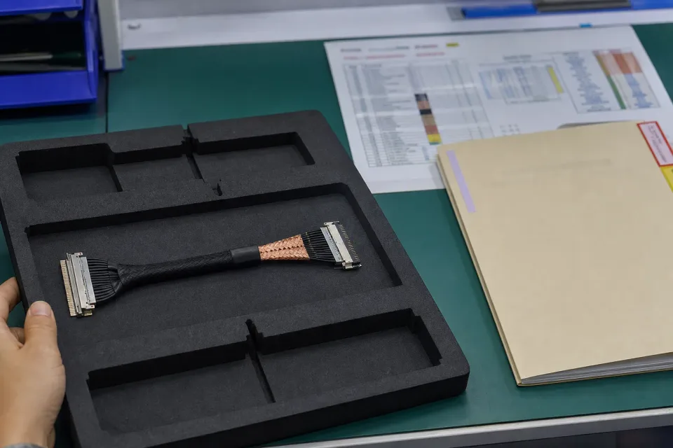
40-pin eDP sample-approval bench with fine-pitch connectors, shield termination detail, and a pinout reference
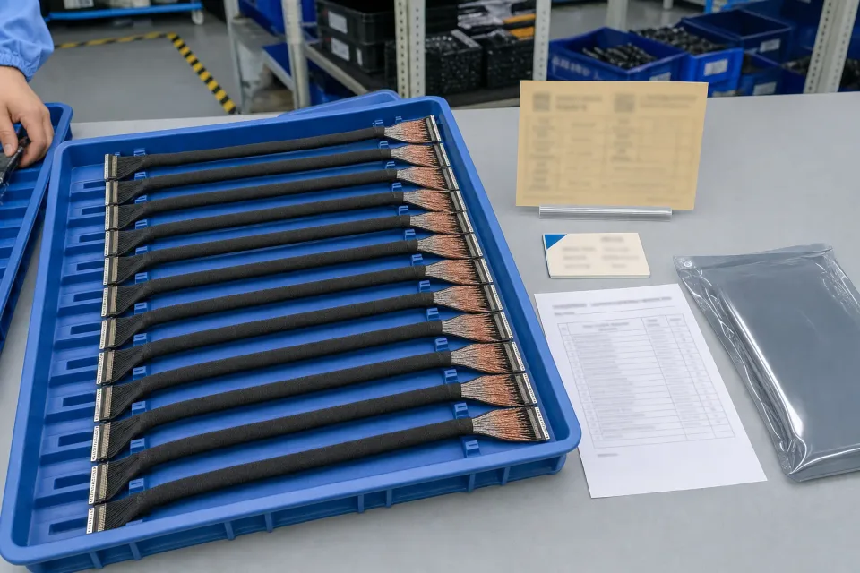
Lot tray of finished 40-pin eDP harnesses showing consistent shield treatment, revision identification, and protective packaging
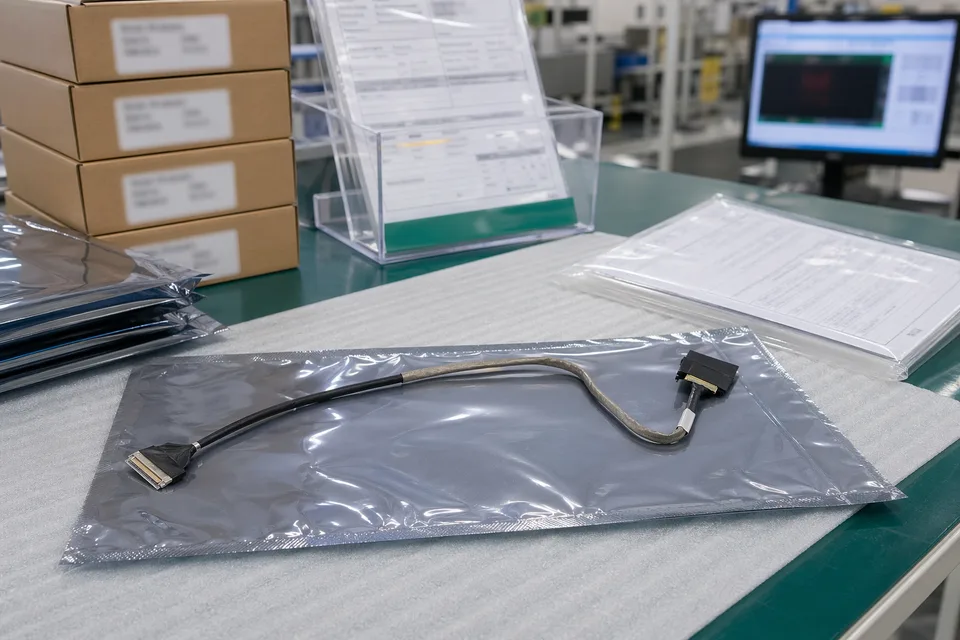
eDP revision traceability record with protected cable sample and controlled document sleeves
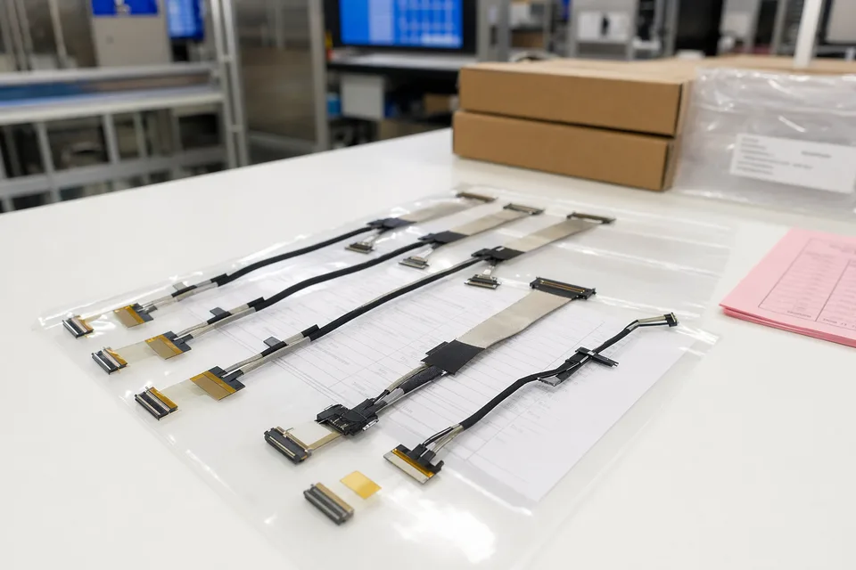
eDP batch release file scene with connector lot labels and display harness support context
FAQ
Can you build 40-pin eDP cables from samples or old parts?
Yes. Existing samples or old parts often make 40-pin review faster, but connector references, shielding expectations, installation conditions, and revision scope still need to be confirmed alongside them.
What is the minimum information needed for a 40-pin quotation?
At minimum, provide connector references or clear photos, pin definition, shielding notes, target length, installation conditions, project stage, and expected quantity.
Does 40-pin automatically mean the project is for higher-resolution displays?
No. Pin count does not define resolution or bandwidth. Those depend on the released panel interface, connector pair, pin assignment, electrical requirements, and system design.
Can one 40-pin eDP harness be shared across multiple panel versions?
Sometimes, but not from pin count alone. Shared use usually depends on connector family, pin definition, shielding structure, length allocation, and route conditions.
Can you evaluate the project if we only have an old sample and no full drawing?
Yes, but add connector photos, shielding expectations, length, installation context, and the current device structure. The old sample alone is usually not enough to represent the formal released version.