Technical Reference · INDUSTRIAL-DISPLAYS
Industrial Display eDP
Custom eDP Cable Assemblies for Industrial Display Programs
For industrial monitors, display modules, and control terminals that need stable internal-display routing
EDPcable supports custom eDP cable assemblies for industrial displays, display modules, control terminals, and other systems that need a stable internal-display path. The practical challenge is usually not whether the harness can be built, but whether connector matching, route geometry, shielding execution, installation boundaries, and revision scope all fit the current platform under one released definition.
Quick Links
QUICK ACCESSStart with the sections closest to the project structure, interface requirements, and validation scope.
Industrial-Display eDP Product Overview
Industrial-display eDP programs work best when the product context is already clear and the next review can focus on route fit, shielding logic, installation space, and revision control. Before sampling, make sure the connector path, route conditions, shielding expectations, and version boundaries are already framed together.
| NO | Item | Typical Range or Meaning |
|---|---|---|
| 01 | Common Use | Industrial displays, display modules, control terminals, internal display retrofit work |
| 02 | Key Inputs | Connector references, pin mapping, route path, shielding notes, version scope |
| 03 | Engineering Focus | Route stability, shielding execution, fixing method, installation space |
| 04 | Quality Focus | Stable termination, repeatable routing, drawing-to-batch consistency |
| 05 | Release Basis | Connector path, shielding notes, installation boundaries, and revision-controlled records |
Customer Pain Points
Industrial-display eDP projects often sound straightforward because the application context is already clear. In real RFQ and sample work, the bigger delays usually come from shielding, route fit, installation-space limits, and revision control rather than from the interface name alone.
| NO | Customer Pain Point | Typical Risk | What Needs Early Confirmation |
|---|---|---|---|
| 01 | Product design issues | The connector path, shielding stack, or route geometry does not truly fit the enclosure, so the sample only becomes a temporary reference | Connector references, route path, shielding conditions, and installation space |
| 02 | Product quality issues | Termination, route execution, or shielding behaviour drifts across batches | Structure definition, quality focus, and revision linkage |
| 03 | Lead-time issues | Incomplete route and shielding inputs force repeated sample loops and slow quotation or release | Connector data, installation boundaries, project stage, and quantity rhythm |
| 04 | After-sales issues | It becomes hard to tell whether the issue came from route geometry, shielding, revision, or service conditions | Drawing files, sample approval records, batch labels, and shipment records |
| 05 | Complaint-handling issues | Revision boundaries are unclear, so issue tracing stays slow | Revision confirmation, batch correspondence, and inspection records |
| 06 | Pricing issues | Scope sounds simple, but shielding, route fit, and revision requirements keep moving later | Structure complexity, material expectations, quantity, and timing |
Product Applications
Industrial-display eDP is not only an interface path. It usually appears in systems where route stability, shielding, service conditions, and revision discipline all matter. The five scenes below are the most common application contexts.
| NO | Application Scene | Scene Focus | Typical Concerns |
|---|---|---|---|
| 01 | Industrial monitors | The display path must stay stable inside a more demanding environment | Fixing method, shielding, lead-time stability, and batch consistency |
| 02 | Embedded industrial display modules | More structure edges and longer routes appear | Length distribution, installation space, revision-sharing boundaries |
| 03 | Control-terminal display units | The interface and installation conditions are more fixed | Connector matching, route stability, and file correspondence |
| 04 | HMI panels | Batch rhythm and replacement frequency both matter | Revision management, packaging labels, and delivery timing |
| 05 | Outdoor or harsh-environment display terminals | Structure protection and long-term repeatability matter more | Shielding boundaries, protection method, and after-sales traceability |
Application Scene Visuals
IMAGES · 05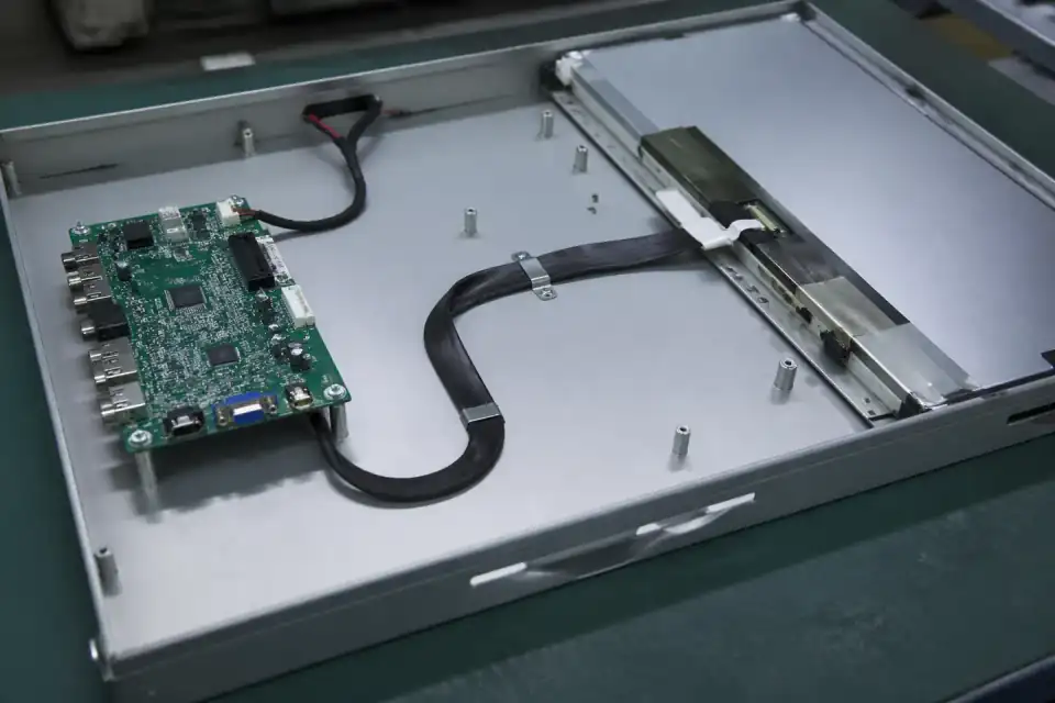
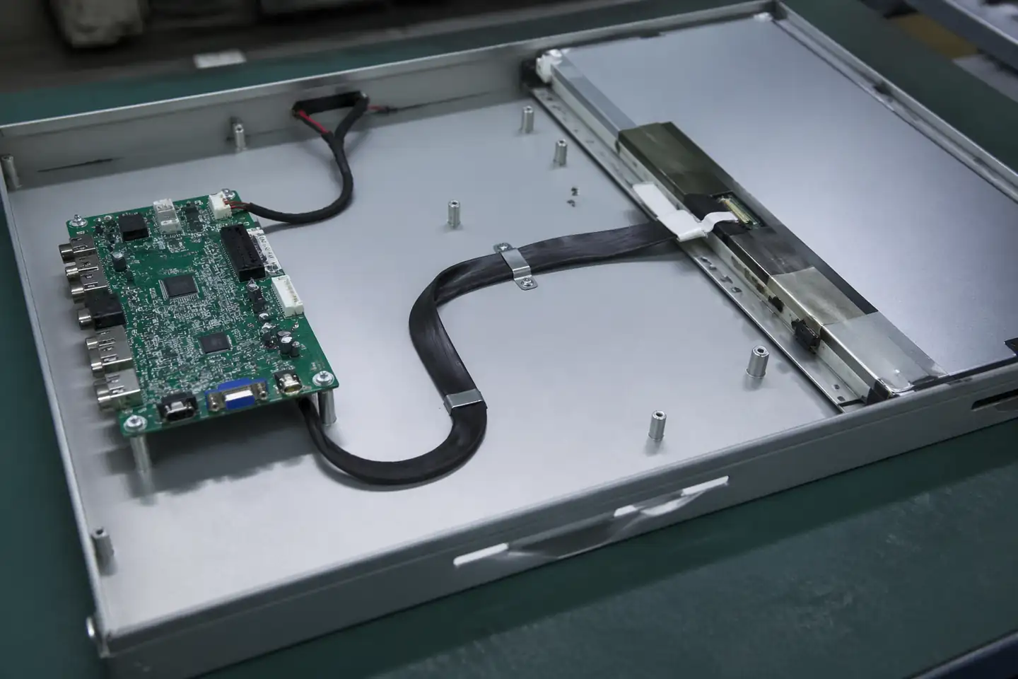
eDP route inside an industrial monitor chassis with stable routed display path
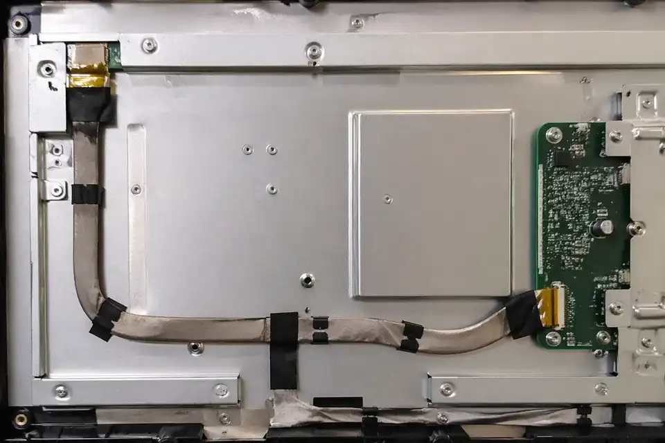
eDP route inside an embedded industrial display module with longer internal path
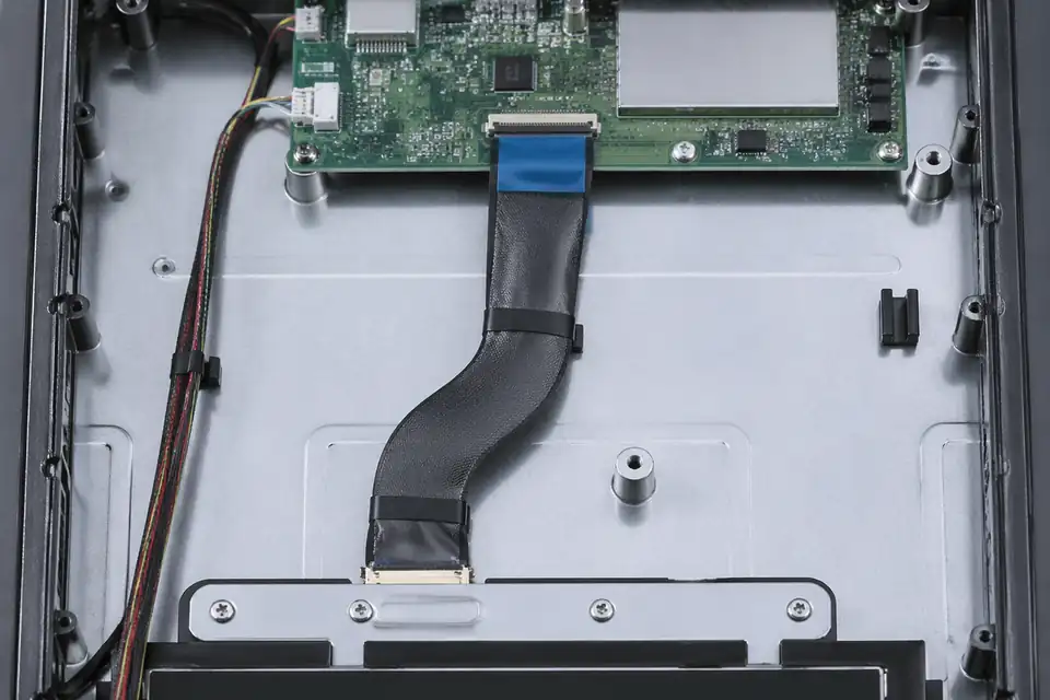
eDP route inside a control-terminal display unit with fixed installation layout
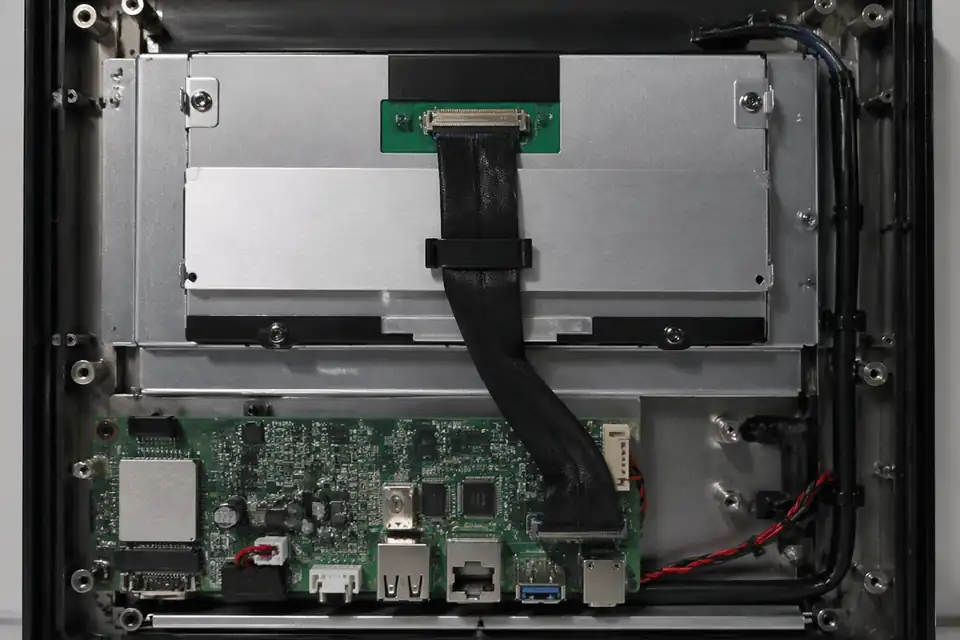
eDP route inside an HMI panel display unit with compact service-ready layout
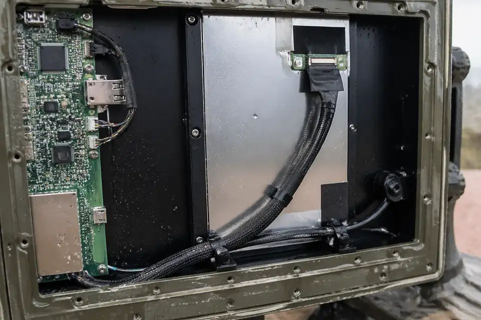
eDP route inside a rugged outdoor display terminal with protected routed harness
Translate the Industrial Enclosure Into Harness Inputs
An industrial-display harness is defined by its actual cabinet, controller, panel, maintenance method, and environmental profile. Generic temperature or vibration labels are not substitutes for product requirements.
| NO | System input | Project detail to capture | Harness design output |
|---|---|---|---|
| 01 | Controller and panel | Exact board and display revisions | Connector pair and net map |
| 02 | Cabinet route | Edges, fans, hinges, covers, and access zones | Dimensioned path with protected transitions |
| 03 | Operating environment | Program temperature, humidity, and contamination profile | Approved material and protection choices |
| 04 | Mechanical exposure | Vibration sources and expected service handling | Restraint points and allowable movement |
| 05 | EMC architecture | Chassis bonds, noisy loads, and cable crossings | Shield and ground termination drawing |
| 06 | Maintenance model | Panel removal direction and technician access | Service loop and labeling scheme |
| 07 | Supply continuity | Approved manufacturers and lifecycle constraints | Controlled BOM with alternates qualified separately |
First-Party Engineering References
- VESA Embedded DisplayPort Standard 1.5 announcement
eDP protocol context for embedded displays; enclosure, durability, and EMC limits come from the industrial product plan.
Industrial Display Failure Modes by Exposure
Risk review should connect each exposure to a physical location in the machine, making countermeasures inspectable on both the drawing and the assembled unit.
| NO | Exposure-driven failure | Mechanism | Design response |
|---|---|---|---|
| 01 | Abraded insulation | Cable contacts a raw edge or moving cover | Add edge protection and positive restraint |
| 02 | Connector fretting | Uncontrolled motion reaches the mating interface | Support mass away from the tail |
| 03 | Display upset near loads | Harness shares a route with switching conductors | Re-route and apply reviewed grounding |
| 04 | Contamination at contacts | Service opening exposes an unprotected interface | Define covers and handling controls |
| 05 | Wrong replacement installed | Visually similar service parts lack revision identity | Use readable platform-specific labels |
Industrial Display Validation in the Real Cabinet
Bench tests cover workmanship, while release testing must reproduce the intended enclosure, grounding, operating modes, and environmental sequence defined by the equipment owner.
| NO | Validation activity | Test configuration | Required outcome |
|---|---|---|---|
| 01 | Installation audit | Production-intent cabinet with covers and restraints | Routing matches the released work instruction |
| 02 | Electrical inspection | Approved harness tester and project net list | Continuity and isolation meet drawing limits |
| 03 | Temperature operation | Run the named temperature profile and dwell at worst-case panel load while logging link faults | Results and post-test inspection meet the cited test-plan limits |
| 04 | Mechanical exposure | Equipment vibration profile and installed harness | No disengagement, chafe, or intermittent result |
| 05 | System EMC | Final grounding state with representative nearby loads | Recorded emissions and immunity results meet the named limits in the approved equipment test plan |
| 06 | Service simulation | Specified panel replacement and reassembly procedure | Latch engagement, continuity, routing, and restraint pass the documented post-service checks |
Engineering Capability
Engineering value in an industrial-display page comes from tying route stability, shielding logic, and service-space limits together before release. Cross-family engineering review, drawing control, and documentation practice are covered in the Related Capability Pages below.
Engineering Capability
Review route path, shielding, and installation space as one engineering problem.
Treat fixing points and service-space boundaries as part of the same release definition.
Confirm whether panel variants, enclosure changes, or field-service constraints affect the route before sample release.
Quality and Verification Highlights
Focus on repeatable route execution and stable shielding behaviour.
Watch connector tails, turn zones, and fixing points closely in installed builds.
Keep batch inspection and shipment labels tied to the industrial-display version so service or replacement issues can be traced later.
Evidence Chain
Sample Approval and Installed-Fit Records
Use sample confirmation records and fit-review notes to show whether the approved sample actually matches the route, shielding, and installation conditions being quoted.
Shielding and Service-Clearance Notes
Capture shielding structure, fixing method, service-space limits, and enclosure conditions that are specific to the industrial-display build.
Field Revision and Batch Records
Connect drawing revision, inspection output, batch labels, and shipment documents so repeat orders remain aligned with the installed display version.
Files and Batch Support
Industrial-display work has its own document layer around shielding and material definitions. Cross-family file control, batch traceability, and certification practice are summarised in the Related Capability Pages.
Shielding and material-definition records
Write shielding structure, wrap choices, and key material notes clearly enough that later structural differences can be traced back to the right layer of change.
Certifications / Records Visuals
IMAGES · 04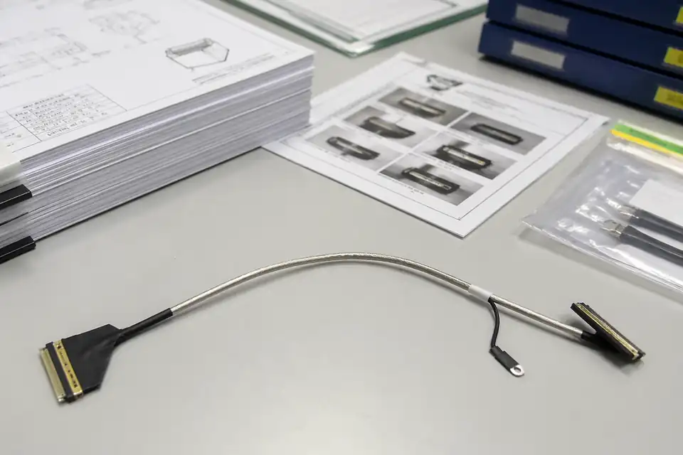
eDP cable assembly with document-control and sample-approval files
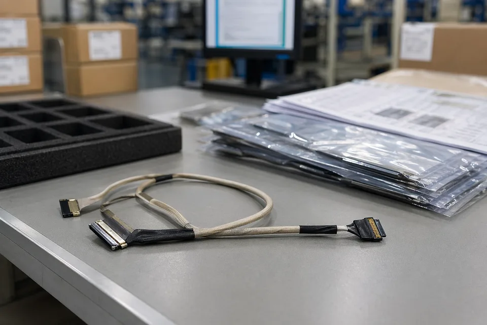
eDP controlled drawing and sample approval record scene with harness sample foreground
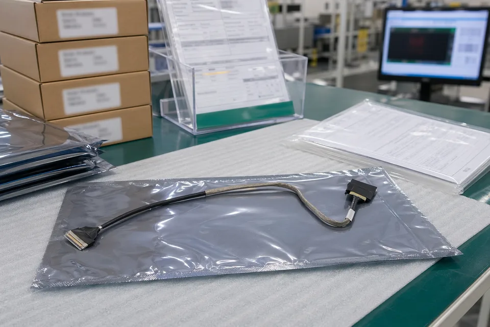
eDP revision traceability record with protected cable sample and controlled document sleeves
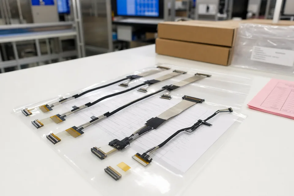
eDP batch release file scene with connector lot labels and display harness support context
FAQ
Can you review an industrial-display project from an old sample?
Yes. Old samples help, but the current route path, shielding logic, and platform version still need to be checked before the sample can represent the released build.
What is the minimum input for an industrial-display eDP quotation?
Send connector references, pin mapping, route context, shielding notes, project stage, and expected quantity.
Why do industrial-display projects need more than a connector reference?
Because installation space, shielding execution, and route stability often decide whether the cable can actually be released cleanly.
Can one eDP harness serve multiple industrial display versions?
Sometimes, but only if connector fit, route geometry, and version boundaries stay inside the same approved definition.
Can review start before the full drawing package is complete?
Yes. Start with the panel and controller references, cabinet route, grounding concept, and exposure profile; freeze dimensions and verification limits as the equipment drawing matures.