Technical Reference · MEDICAL-DISPLAYS
Medical Display eDP Interconnects
Custom eDP Cable Assemblies for Medical Display Systems
For medical monitors, diagnostic displays, and specialty display modules that need stable internal routing and controlled release logic
EDPcable supports custom eDP cable assemblies for medical display systems, diagnostic displays, specialty monitor modules, and other programs where internal display routing, shielding behaviour, installation fit, and version-linked records all matter. The challenge is not getting one sample made. It is making sure connector references, route path, shielding execution, and released documents all stay aligned with the active medical-device platform.
Quick Links
QUICK ACCESSStart with the sections closest to the project structure, interface requirements, and validation scope.
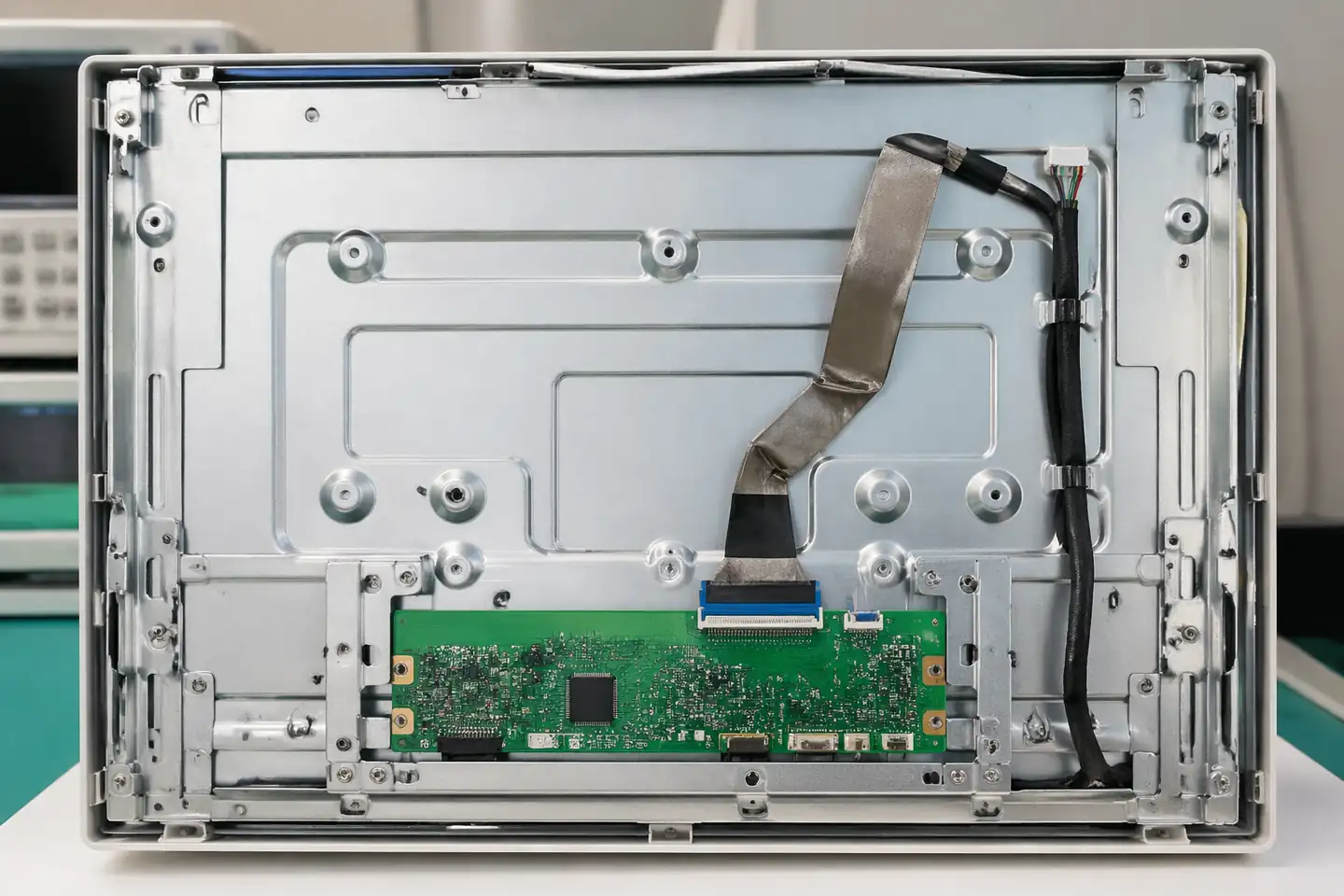
Medical Display eDP Product Overview
Medical-display eDP programs work best when the device context is already clear and the next review can focus on connector definition, route path, shielding structure, installation fit, and released version boundaries before sampling.
| NO | Item | Typical Range or Meaning |
|---|---|---|
| 01 | Typical Devices | Medical monitors, diagnostic displays, specialty display modules, regulated internal display systems |
| 02 | Common Structures | Internal eDP harnesses, shielded routed assemblies, compact monitor-side interconnects |
| 03 | Key Inputs | Connector references, pin definition, route path, shielding notes, version scope |
| 04 | Use Focus | Signal stability, installation fit, validation support, released-record correspondence |
| 05 | Quality Focus | Termination consistency, shielding execution, clear records, repeatable batches |
| 06 | Release Basis | Connector data, route notes, shielding logic, and active platform-version boundaries |
Customer Pain Points
Medical-display eDP projects often sound straightforward once the product or route category is known. In real RFQ and sample work, delays usually appear in route fit, structure judgement, and revision control rather than in the label alone.
| NO | Customer Pain Point | Typical Risk | What Needs Early Confirmation |
|---|---|---|---|
| 01 | Product design issues | The connector path, structure, or local fit still does not truly match the medical-display eDP build, so the sample becomes only a temporary reference | Connector references, route path, structure boundaries, and installation space |
| 02 | Product quality issues | Execution, local fit, or batch consistency drifts across repeated medical-display eDP builds | Structure definition, quality focus, and revision linkage |
| 03 | Lead-time issues | Missing inputs force repeated sample loops and slow quotation, release, and batch timing | Connector data, route notes, project stage, quantity, and timing |
| 04 | After-sales issues | It becomes difficult to tell whether the issue came from structure, revision, or installed conditions | Drawing files, sample approval records, batch labels, and shipment records |
| 05 | Complaint-handling issues | Revision boundaries are unclear, so issue tracing stays slow | Revision confirmation, batch correspondence, and inspection records |
| 06 | Pricing issues | A broad request turns into repeated pricing changes once real fit constraints surface | Structure complexity, material expectations, quantity, and delivery boundaries |
Product Applications
This route is not only a category label. In practice, medical-display eDP work usually appears in device programs where fit, route logic, and revision scope all matter. The scenes below are the most common application contexts.
| NO | Application Scene | Scene Focus | Typical Concerns |
|---|---|---|---|
| 01 | Bedside-monitor displays | released routing and monitor-side fit under active device versions | connector matching, route clearance, and record correspondence |
| 02 | Diagnostic display systems | stable internal-display signal execution with controlled version boundaries | shielding logic, route path, and validation support |
| 03 | Specialty display modules | compact routed assemblies inside tighter medical housings | installation limits, fixing logic, and structure discipline |
| 04 | Replacement and upgrade programs | matching old display routes to the active released platform | usable scope, sample confirmation, and after-sales tracing |
| 05 | Validation-heavy pilot builds | sample-to-release continuity before batch introduction | document control, approval records, and batch readiness |
Application Scene Visuals
IMAGES · 05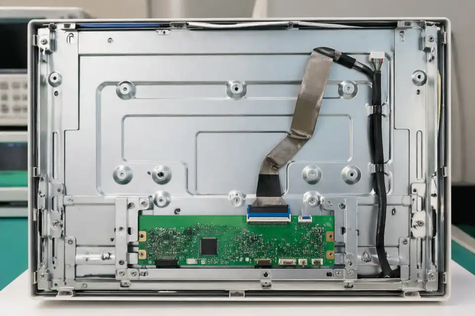
eDP route inside a diagnostic display terminal with controlled medical display context
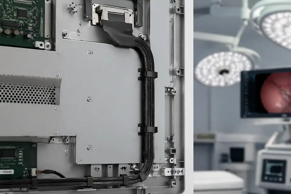
eDP route inside a surgical display system with stable release-disciplined internal layout
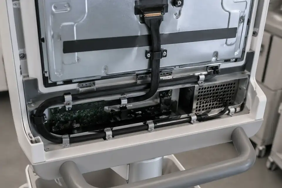
eDP route inside a mobile medical cart display unit with compact protected routing
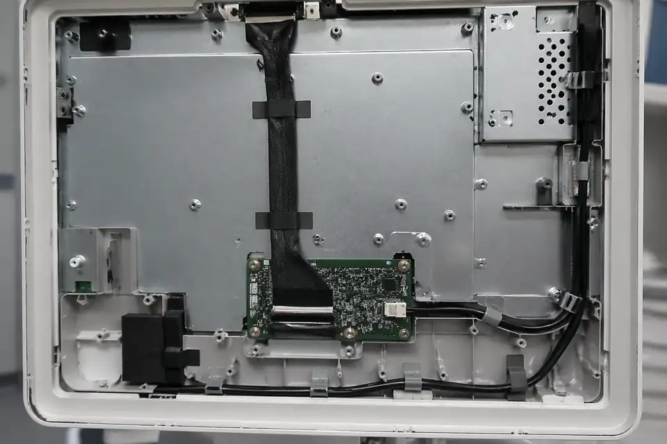
eDP route inside a medical workstation display module with serviceable internal layout
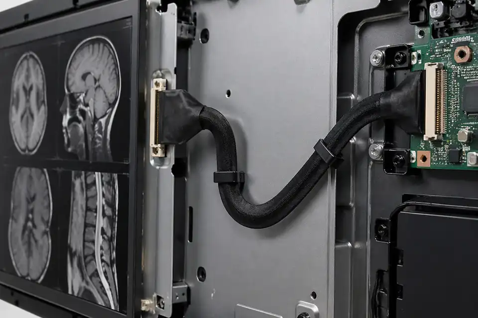
eDP route inside an imaging-review display device with quality-focused signal path
Define the eDP Assembly Within the Medical Device File
For a medical display, the harness is controlled through the device manufacturer's risk management, electrical architecture, usability needs, and change process. A component description must not imply device-level compliance.
| NO | Design-file input | Harness implication | Controlled record |
|---|---|---|---|
| 01 | Intended device configuration | Names the exact display and processor assembly | Approved platform applicability list |
| 02 | Safety architecture | Identifies relevant circuits, separation, and grounding constraints | Reviewed schematic-to-harness mapping |
| 03 | Essential display functions | Defines operating modes requiring verification | System test traceability matrix |
| 04 | Cleaning and service | Sets exposure, access, and replacement conditions | Material and work-instruction requirements |
| 05 | EMC risk controls | Locates sensitive circuits and shield terminations | Grounding and routing definition |
| 06 | Connector and cable BOM | Fixes manufacturers, suffixes, and approved materials | Purchasing specification with change control |
| 07 | Identification strategy | Separates device and panel revisions | Label content linked to device history |
First-Party Engineering References
- IEC 60601-1 consolidated edition listing
Device-level basic safety and essential-performance context; citation does not certify a cable assembly.
- VESA Embedded DisplayPort Standard 1.5 announcement
eDP interface context only; the medical device manufacturer selects the applicable revision and controls.
Medical Display Harness Risk-control Review
Failure modes should be evaluated in the device risk file with their clinical and service consequences, then translated into measurable manufacturing and system controls.
| NO | Hazard-related failure | Initiating condition | Traceable control |
|---|---|---|---|
| 01 | Loss of required image | Open circuit, poor mate, or incompatible panel map | Functional test covers defined essential modes |
| 02 | Intermittent display response | Routing stress reaches a connector or termination | Installed strain relief is inspected |
| 03 | EMC susceptibility change | Shield or return implementation differs from release | Device EMC configuration controls assembly |
| 04 | Service replacement error | Similar harnesses lack clear applicability marking | Part identity is checked during service |
| 05 | Unassessed material change | Supplier substitution bypasses device evaluation | Change notification precedes production use |
Medical Display Verification With Traceable Configurations
The verification report should identify the harness lot and the exact device configuration, allowing results to support the manufacturer's design history and later change assessment.
| NO | Verification layer | Planned activity | Objective evidence |
|---|---|---|---|
| 01 | Supplier documentation | Review certificates and controlled material declarations requested by BOM | Documents match received manufacturer lots |
| 02 | First article | Inspect dimensions, identity, workmanship, and all electrical nets | Approved report references the released drawing |
| 03 | Installed function | Exercise device-defined display states and fault monitoring | Results map to system requirements |
| 04 | EMC configuration | Test with final enclosure, grounding, peripherals, and software | Measured results meet each limit identified by test ID in the approved device EMC plan |
| 05 | Cleaning and service | Apply specified handling and replacement procedures | No lock damage, continuity loss, route change, residue, or material change beyond the documented rejection criteria |
| 06 | Change assessment | Compare proposed materials or processes to qualified baseline | Device owner approves impact before release |
Engineering Capability
Medical-display eDP engineering review should connect connector definition, shielded route path, installation fit, and released records before sampling. Cross-family drawing control and documentation practice are covered in the Related Capability Pages below.
Engineering Capability
Confirm connector references, pin definition, shielding expectation, route path, and medical-display platform version together.
Review internal monitor layout, fixing points, bend zones, and protection method before the sample is treated as validation-ready.
Define whether replacement, diagnostic, bedside, or mobile-display versions share one released cable scope or require separate definitions.
Quality and Verification Highlights
Check connector tails, shielding transitions, route protection, and visual condition in the areas most likely to affect display reliability.
Keep inspection output, sample approval, and shipment-side documents tied to the active medical-display revision.
Watch replacement and multi-version projects carefully so old-sample assumptions do not overwrite current platform requirements.
Evidence Chain
Medical-Display Release Basis
Use connector references, pin definition, shield notes, route path, and platform version to define the cable assembly being reviewed.
Sample Approval and Validation Support
Connect sample confirmation, inspection output, and route-fit notes to the validation stage required by the customer project.
Revision and Shipment Records
Keep batch labels, packing information, and shipment-side files aligned to the current medical-display release boundary.
Files and Batch Support
Medical-display eDP work has its own document layer around route and fitting boundaries. Cross-family file control, batch traceability, and certification practice are summarised in the Related Capability Pages.
Medical-display eDP route and fitting-boundary records
Capture the route path, local fit, and installation-space limits that are specific to the medical-display eDP build so later structural differences can be traced back to the right layer of change.
Certifications / Records Visuals
IMAGES · 04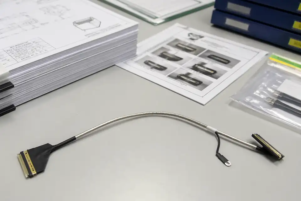
eDP cable assembly with document-control and sample-approval files
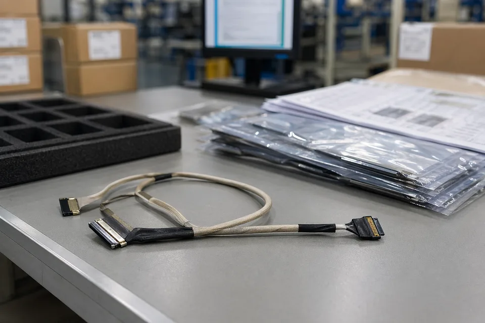
eDP controlled drawing and sample approval record scene with harness sample foreground
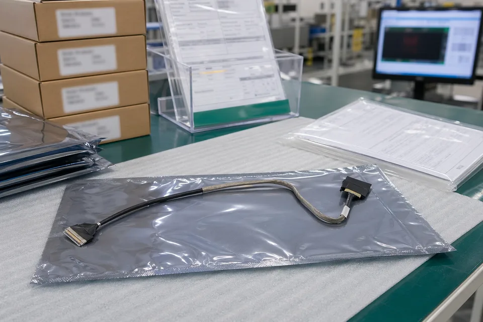
eDP revision traceability record with protected cable sample and controlled document sleeves
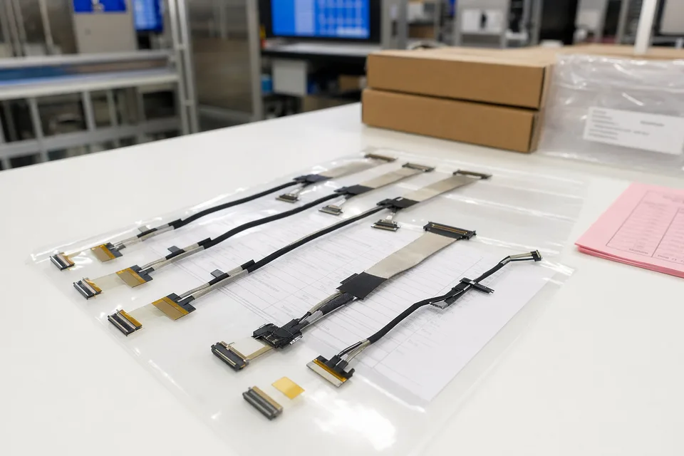
eDP batch release file scene with connector lot labels and display harness support context
FAQ
Can you work from old medical-display eDP samples?
Yes. Old parts help, but connector matching, route path, shielding notes, and active device-version boundaries still need to be checked before the sample can represent the released build.
What is the minimum input for a medical-display eDP quotation?
Send connector references, pin definition, route context, shielding notes, project stage, and expected quantity.
Why do medical-display eDP programs need more than pin count and connector model?
Because installation fit, shielding execution, document control, and version scope often decide whether the assembly can actually be released cleanly.
Can one medical-display eDP assembly cover several monitor versions?
Only when the panel, controller, connector pair, pin map, shield termination, installed route, and controlled device revision remain identical; otherwise the assembly needs a separate review.
Can review start before the full drawing package is complete?
Yes. Early review can start from connector references, route context, and current monitor-side constraints, then tighten as the file package becomes clearer.