Technical Reference · TELECOM-INTERCONNECT
Telecom IDC Interconnect
Custom IDC Cable Assemblies for Telecom Interconnect Programs
For communications hardware, interface extension, and compact IDC routes that need stable line logic
EDPcable supports IDC assemblies for communications hardware, board extensions, compact distribution paths, and serviceable internal interfaces. Confirm connector end views, point-to-point mapping, cable exit, interface density, labels, access clearance, and revision scope against the hardware drawing. Control-cabinet maintenance constraints belong to the industrial-control direction; non-standard conductor order belongs to custom pin mapping.
Quick Links
QUICK ACCESSStart with the sections closest to the project structure, interface requirements, and validation scope.
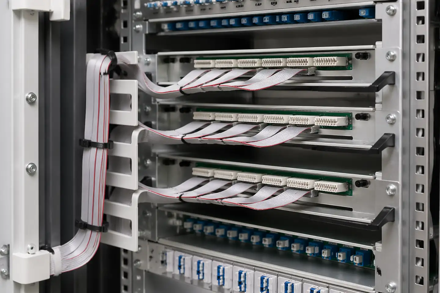
Telecom IDC Product Overview
Telecom IDC programs work best when the hardware context is already clear and the next review can focus on line logic, route fit, interface-space limits, and revision scope before sampling.
| NO | Item | Typical Range or Meaning |
|---|---|---|
| 01 | Typical Use | Communications hardware, interface extension, board-to-board links, compact distribution paths |
| 02 | Key Inputs | Pin mapping, connector form, route path, structure type, revision scope |
| 03 | Engineering Focus | Line-order clarity, route efficiency, structure boundaries, release control |
| 04 | Quality Focus | Repeatable IDC termination, stable route execution, revision-linked records |
| 05 | Release Basis | Mapping logic, route notes, interface-space limits, and revision-controlled records |
Customer Pain Points
Telecom IDC projects often sound simple because the hardware category is already known. In real RFQ and sample work, the bigger delays usually appear in line logic, route fit, compact-space limits, and revision control rather than in pitch alone.
| NO | Customer Pain Point | Typical Risk | What Needs Early Confirmation |
|---|---|---|---|
| 01 | Product design issues | The connector form or route path still does not truly fit the hardware, so the sample becomes only a temporary reference | Connector references, route path, compact-space limits, and structure boundaries |
| 02 | Product quality issues | IDC termination, line logic, or route execution drifts across batches | Structure definition, quality focus, and revision linkage |
| 03 | Lead-time issues | Missing route and fit inputs force repeated sample loops and delay release | Connector data, route notes, project stage, quantity, and timing |
| 04 | After-sales issues | It becomes difficult to tell whether the issue came from line logic, revision, or installed conditions | Drawing files, sample approval records, batch labels, and shipment records |
| 05 | Complaint-handling issues | Revision boundaries are unclear, so issue tracing stays slow | Revision confirmation, batch correspondence, and inspection records |
| 06 | Pricing issues | A broad IDC request turns into repeated pricing changes once real fit constraints surface | Structure complexity, quantity, and delivery boundaries |
Product Applications
Telecom IDC is not only a cable format. It usually appears in hardware programs where line logic, route fit, compact-space limits, and revision scope all matter. The five scenes below are the most common application contexts.
| NO | Application Scene | Scene Focus | Typical Concerns |
|---|---|---|---|
| 01 | Rack-side communications interconnects | Interface count is higher and route density is stronger | Pin mapping, connection logic, file discipline |
| 02 | Board-to-board IDC extensions | Revision and batch control matter more | Structure consistency, labels, timing |
| 03 | Core communications modules | Serviceability matters more | Connector direction, later maintenance, traceability |
| 04 | Signal-distribution systems | Multi-endpoint relationships are more complex | Mapping logic, release scope, quality records |
| 05 | Replacement programs | Legacy interfaces and current hardware conditions must be re-matched | Legacy drawings, usable scope, after-sales handling |
Application Scene Visuals
IMAGES · 05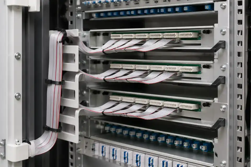
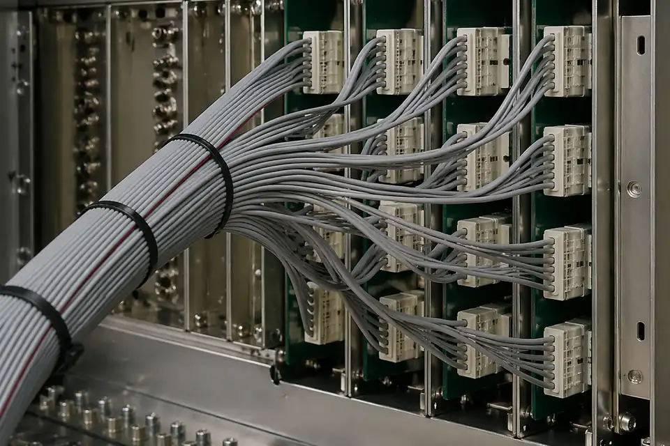
IDC telecom interconnect inside a communications rack with dense connector paths
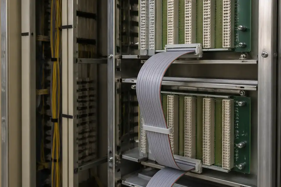
IDC telecom extension between boards inside a communications rack
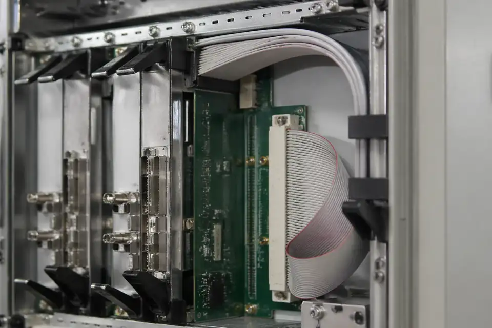
IDC ribbon harness inside a telecom base communication module
IDC ribbon harness in a signal distribution system
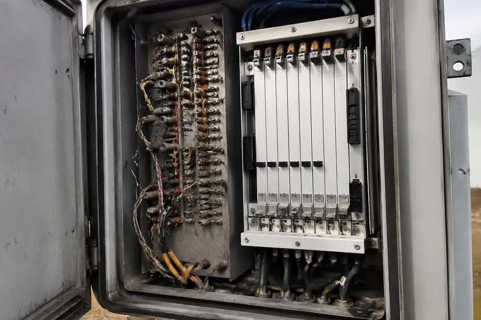
IDC telecom replacement-project context inside a communications unit
Telecom IDC Interface Definition
Define each telecom interconnect from port identity through routing and maintenance access. Electrical performance targets, conductor assignment, grounding, temperature under the defined electrical load, and any length-matching constraint must come from the project channel budget rather than from the generic IDC construction label.
| NO | Interface input | Definition needed | Engineering decision | Controlled source |
|---|---|---|---|---|
| 01 | Endpoint interfaces | Exact connector part numbers, mates, and board references | Confirm compatible geometry, orientation, and service access | Manufacturer and equipment drawings |
| 02 | Port and net map | Source port, destination port, pin allocation, and unused contacts | Release an explicit map for every link and branch | Interface netlist |
| 03 | Return and ground allocation | Project-defined return paths and chassis or logic-ground boundaries | Preserve the equipment grounding scheme in the cable map | System electrical design |
| 04 | Cable exit and stacking | Connector orientation, neighboring plugs, latch access, and bundle order | Allow installation and removal without disturbing adjacent links | Rack or enclosure layout |
| 05 | Route and airflow | Bundle path, vent keep-outs, edge protection, and support points | Control cable placement without obstructing required cooling paths | Installed-route drawing |
| 06 | Length constraints | Maximum path, matching, or skew requirement when defined by the system | Translate only documented channel needs into assembly tolerances | Project channel budget |
| 07 | Power allocation | Current paths, returns, grouping, and simultaneous load assumptions | Evaluate the exact contacts, cable, and installed thermal condition | Power and thermal analysis |
| 08 | Service identity | Link label, endpoint label, revision, and replacement part | Make the logical connection traceable at both installed ends | Maintenance labeling plan |
First-Party Engineering References
- Hirose HIF3B Series
Use only for an exact HIF3B component and its manufacturer-published series information; verify the selected variant and do not treat family or standard references as completed-link performance certification.
- IPC/WHMA-A-620E Release Notice
Use to inform harness process and acceptance planning; telecom channel performance, grounding, current limits, and environmental qualification remain project-specific engineering requirements.
Telecom Link Failure Review
Review the link as an installed, serviceable assembly rather than an isolated continuity path. Mapping, return allocation, bundle placement, latch access, system-specific length constraints, and revision control can each create failures that a simple bench check will not reveal.
| NO | Failure mode | System consequence | Design control | Verification evidence |
|---|---|---|---|---|
| 01 | Mirrored port assignment | A fully terminated cable connects the wrong logical endpoints | Declare connector views and endpoint identifiers on the netlist | Port-specific point-to-point test |
| 02 | Incorrect return allocation | The assembly conflicts with the defined system current or grounding path | Review returns and grounds against the equipment design | Independent electrical design check |
| 03 | Airflow obstruction | Bundle placement compromises the equipment cooling path | Define vent keep-outs and installed support locations | Review in a representative populated enclosure under the defined electrical load |
| 04 | Blocked latch or service access | Adjacent links must be disturbed to replace one cable | Model connector access and sequence with neighboring hardware | Maintenance simulation |
| 05 | Channel-budget nonconformance | Assembly length or routing exceeds a documented system allowance | Carry the project-specific electrical constraints into the assembly drawing | Dimensional and specified channel testing |
| 06 | Revision-incompatible replacement | A spare mates physically but carries an obsolete mapping | Tie link labels and service part numbers to interface revision | Configuration audit before release |
Telecom Interconnect Verification
Verification joins full net testing with enclosure fit, service access, and the system tests explicitly called out by the equipment design. Do not imply a generic bandwidth or transmission rating from connector family literature; record the exact assembly configuration used for any channel measurement.
| NO | Verification activity | Method | Acceptance basis | Configuration record |
|---|---|---|---|---|
| 01 | Endpoint net verification | Test every source port, destination port, and defined branch | Measured map matches the released interface netlist | Serialized electrical report |
| 02 | Isolation and unused-pin check | Test for unintended continuity between circuits that must remain isolated and at declared unused contacts | No unintended path at the project test limits | Tester output |
| 03 | Mating and stacking fit | Install with representative neighboring connectors and enclosure hardware | Full engagement and latch operation remain accessible | First-article fit report |
| 04 | Route and airflow review | Inspect the supported bundle in the intended equipment configuration | Specified vents, fans, covers, and service paths remain clear | Installation review record |
| 05 | Project channel test | Apply the equipment-defined measurement only when required | Results meet the documented system limit for the tested configuration | Channel test report |
| 06 | Loaded thermal check | Operate defined power circuits in the representative installed bundle when required | Temperatures remain within exact component and project limits | Thermal qualification record |
| 07 | Retention and service cycle | Apply defined cable loads and perform representative replacement cycles | No disengagement, damage, map change, or intermittent circuit | Mechanical test result |
| 08 | Configuration trace | Resolve connector, cable, drawing, netlist, and test revisions from the label | The installed link maps to one approved release set | Final acceptance record |
Engineering Capability
Engineering value in a telecom-interconnect IDC page comes from aligning line logic, route fit, and compact-space limits before release. Cross-family engineering review, drawing control, and documentation practice are covered in the Related Capability Pages below.
Engineering Capability
Review pin mapping, route path, and interface-space limits together in the real hardware context.
Treat structure type and connector direction as part of the same release definition.
Quality and Verification Highlights
Focus on repeatable IDC termination, stable route execution, and clean line-order control.
Watch branch points, interface exits, and compact-space fit closely in installed builds.
Evidence Chain
Sample Approval and Installed-Fit Records
Use sample confirmation records and route-review notes to show whether the approved sample actually matches the compact route, interface-space limits, and installed conditions being quoted.
Telecom Mapping and Replacement Records
Telecom IDC work is release-sensitive: endpoint identifiers, legacy pin maps, crossover logic, connector keying, branch labels, and rack-side routing all need a common revision basis.
Endpoint and mapping definition
Record both equipment endpoints, connector viewing direction, Pin 1, straight-through or crossover logic, branch sequence, and required end labels.
Mapping verification and fit record
Keep continuity or netlist verification with the sample-fit result for the target chassis, rack position, bend path, and service-access condition.
Legacy-version traceability
Tie the shipped assembly to the equipment family, interface revision, and released mapping so later replacements do not rely on connector appearance alone.
Branch and end-label protection
Arrange packing so branches remain ordered, end identifiers stay legible, and keyed connector features are not loaded during transport.
Certifications / Records Visuals
IMAGES · 04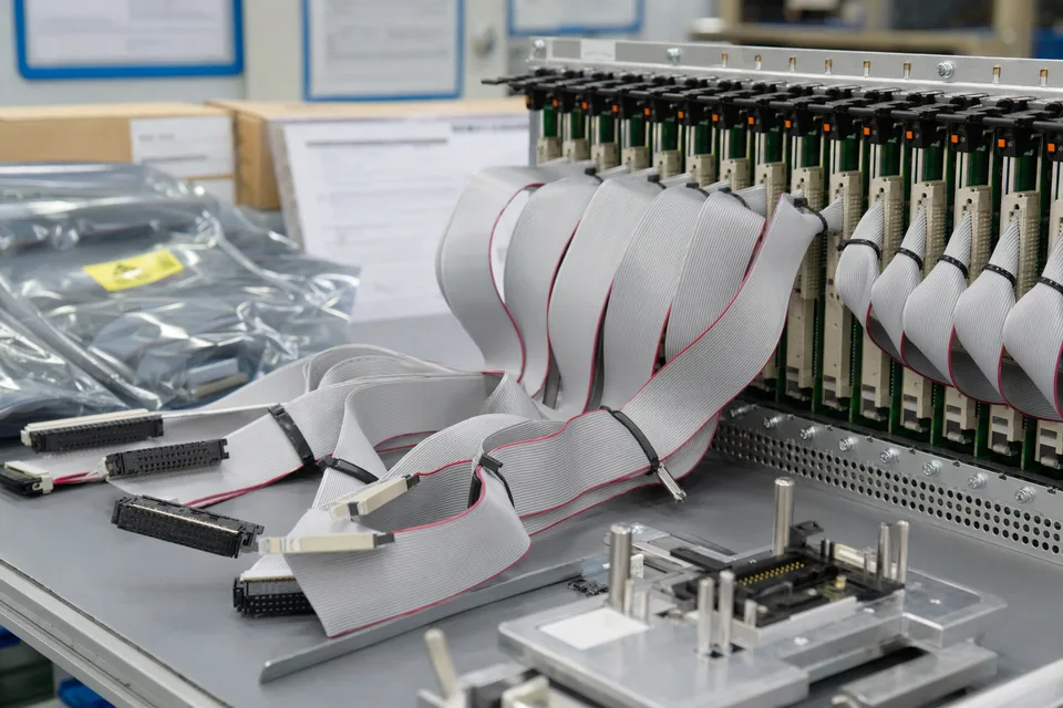
Telecom IDC interconnect release-record scene with rack-module harness sample and document sleeves secondary
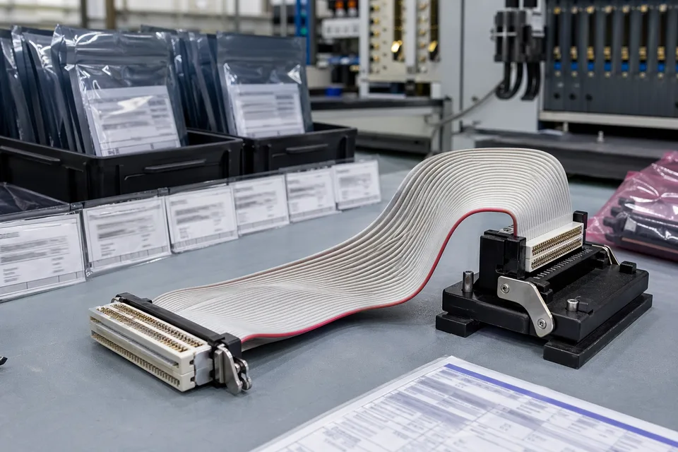
Telecom IDC batch traceability archive with connector lot cards and ribbon assembly foreground
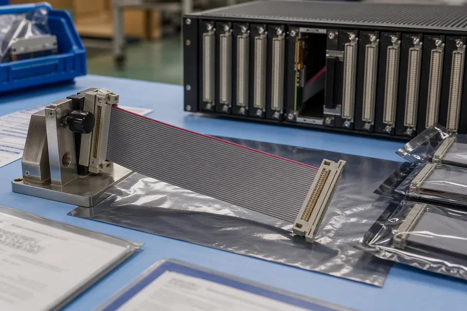
Telecom backplane IDC sample approval record with controlled folder and module mockup support
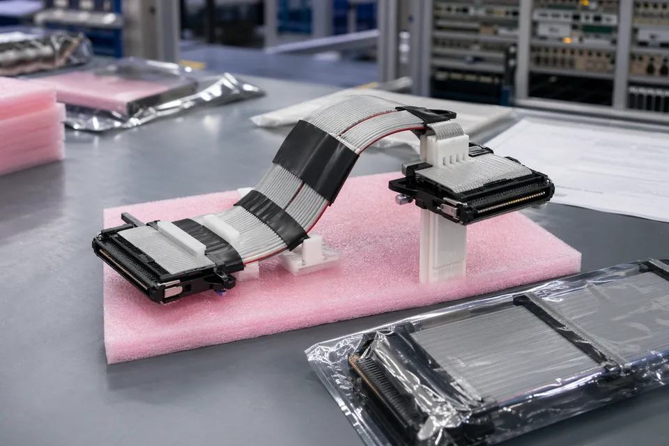
Telecom IDC harness sample with revision-controlled drawings and inspection records
FAQ
Can you review a telecom project from an old sample?
Yes. Old parts help, but the current route path, line logic, and hardware revision still need to be checked before the sample can represent the released build.
What is the minimum input for a telecom IDC quotation?
Send connector references, pin mapping, route context, project stage, and expected quantity.
Why do telecom IDC projects need more than a pitch or connector reference?
Because line logic, route fit, compact space, and structure boundaries often decide whether the cable can be released cleanly.
Can one telecom IDC assembly serve several versions?
Sometimes, but only if mapping logic, route geometry, and revision scope stay inside the same approved definition.
Can review start before the full drawing package is complete?
Yes. Begin with port identities, the draft conductor map, grounding allocation, populated-enclosure route, and channel budget; add numeric electrical limits as the telecom hardware definition closes.