Technical Reference · RIBBON-IDC
Standard Ribbon IDC
Custom Ribbon IDC Configurations
For standard ribbon, flat-cable, and repeatable IDC assembly formats
EDPcable supports standard straight-through ribbon IDC assemblies where conductor order follows the connector positions shown on the released drawing. Confirm pitch, pin count, Pin 1, connector viewing direction, keying, cable exit, strain relief, and route clearance before termination setup. Cross-over, breakout, or reordered conductors belong to the custom pin-mapping direction.
Quick Links
QUICK ACCESSStart with the sections closest to the project structure, interface requirements, and validation scope.
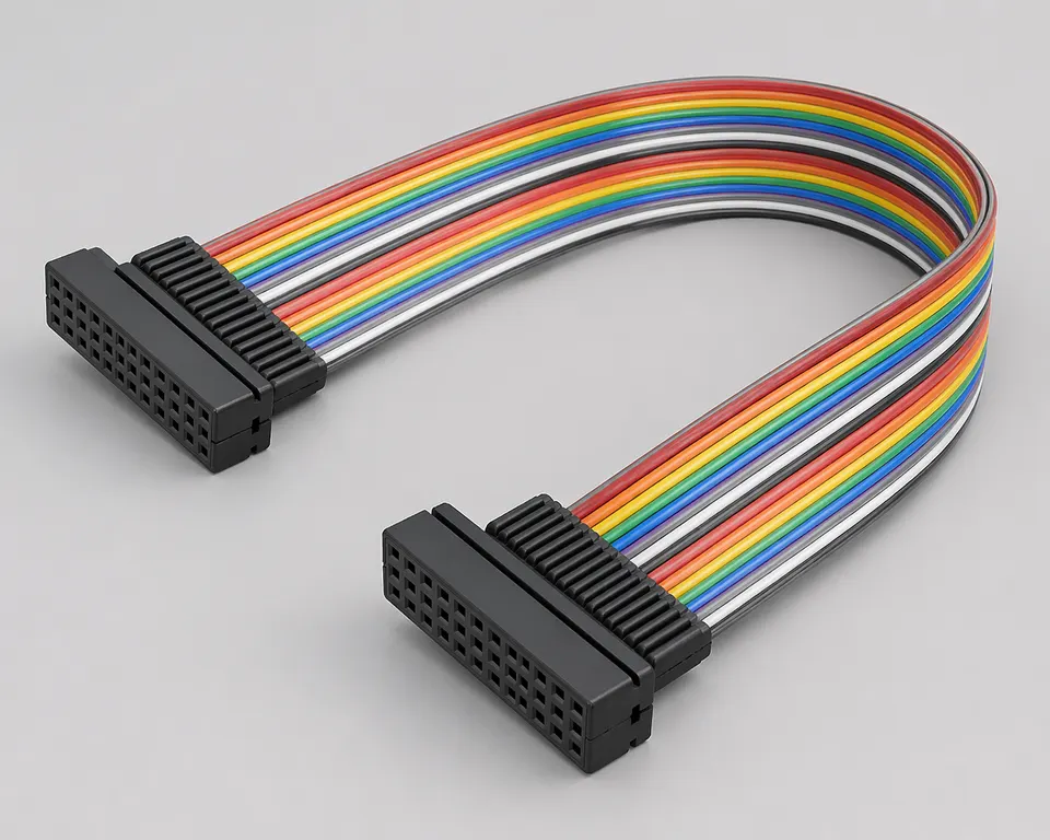
Ribbon IDC Product Overview
Ribbon IDC programs work best when the standard format is already clear and the next review can focus on pitch, pin count, route fit, connector orientation, and revision scope before sampling.
| NO | Item | Typical Range or Meaning |
|---|---|---|
| 01 | Common Use | Standard ribbon links, flat-cable assemblies, routine IDC extensions, board-to-board links |
| 02 | Key Inputs | Pitch, pin count, connector form, route path, version scope |
| 03 | Engineering Focus | IDC termination setup, route fit, connector orientation, release boundaries |
| 04 | Quality Focus | Repeatable IDC termination, stable connector position, batch-linked records |
| 05 | Release Basis | Connector references, pitch data, route notes, and version-controlled records |
Engineering Inputs
Use these items as first-round review inputs so the discussion does not rely on the page label alone.
Send connector references or clear mating photos.
Include pitch, pin count, route path, and key local-fit notes.
Add installation-space limits and any retention or fixing requirements.
Describe project stage, expected quantity, and timing target.
Explain any version boundaries that affect the standard configuration.
Customer Pain Points
Ribbon IDC projects often sound straightforward once the product or route category is known. In real RFQ and sample work, delays usually appear in route fit, structure judgement, and revision control rather than in the label alone.
| NO | Customer Pain Point | Typical Risk | What Needs Early Confirmation |
|---|---|---|---|
| 01 | Product design issues | The connector path, structure, or local fit still does not truly match the ribbon IDC build, so the sample becomes only a temporary reference | Connector references, route path, structure boundaries, and installation space |
| 02 | Product quality issues | Execution, local fit, or batch consistency drifts across repeated ribbon IDC builds | Structure definition, quality focus, and revision linkage |
| 03 | Lead-time issues | Missing inputs force repeated sample loops and slow quotation, release, and batch timing | Connector data, route notes, project stage, quantity, and timing |
| 04 | After-sales issues | It becomes difficult to tell whether the issue came from structure, revision, or installed conditions | Drawing files, sample approval records, batch labels, and shipment records |
| 05 | Complaint-handling issues | Revision boundaries are unclear, so issue tracing stays slow | Revision confirmation, batch correspondence, and inspection records |
| 06 | Pricing issues | A broad request turns into repeated pricing changes once real fit constraints surface | Structure complexity, material expectations, quantity, and delivery boundaries |
Product Applications
Standard ribbon IDC assemblies suit straight-through links where pitch, Pin 1, connector orientation, cable exit, and route clearance can be fixed on one released drawing.
| NO | Application Scene | Scene Focus | Typical Concerns |
|---|---|---|---|
| 01 | Standard ribbon interconnects | pitch consistency and repeatable connector alignment | pin count, termination setup, and batch stability |
| 02 | Board-to-board IDC extensions | clean route fit inside tighter equipment layouts | connector orientation, local clearance, and version scope |
| 03 | Flat-cable equipment routes | repeatable routing inside internal equipment space | local fit, fixing method, and service access |
| 04 | Replacement programs | matching old flat-cable builds to the active platform | route correspondence, released definition, and issue tracing |
| 05 | Compact control modules | stable batch execution under standard IDC rules | delivery rhythm, batch labels, and repeat supply |
Application Scene Visuals
IMAGES · 05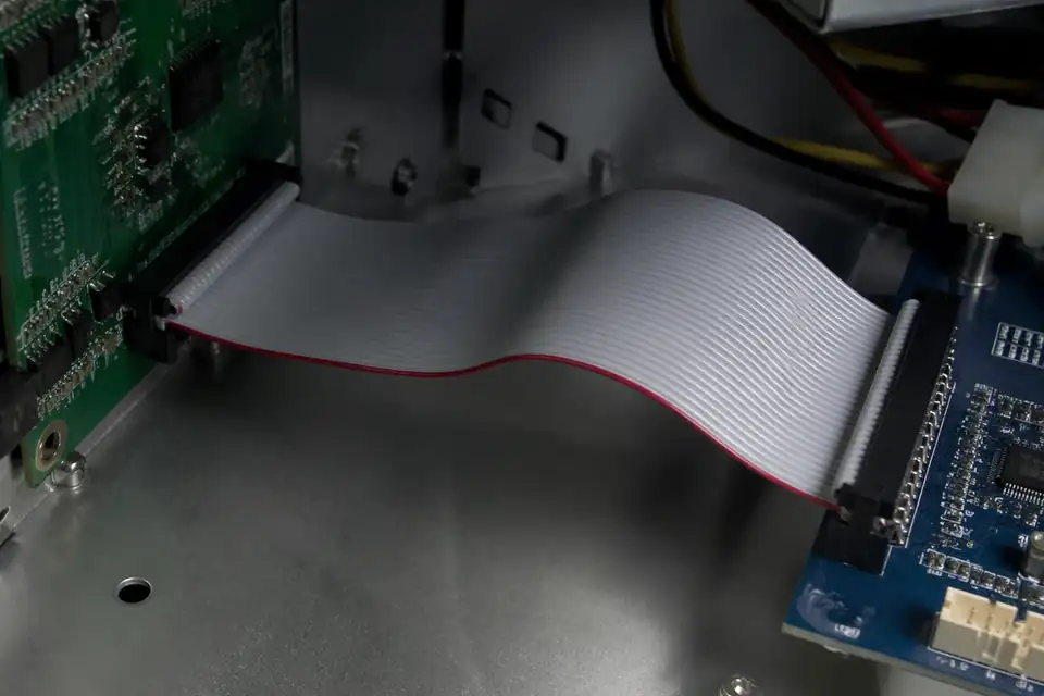
Ribbon IDC assembly in a standard board-to-board ribbon connection
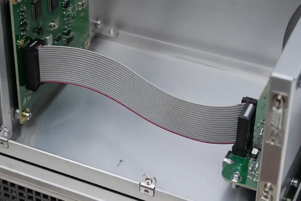
Ribbon IDC assembly used as a board-extension ribbon path
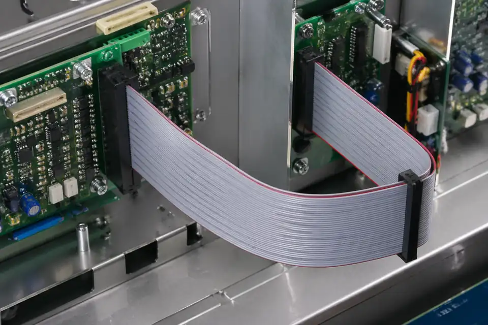
Ribbon IDC assembly connecting control modules inside equipment
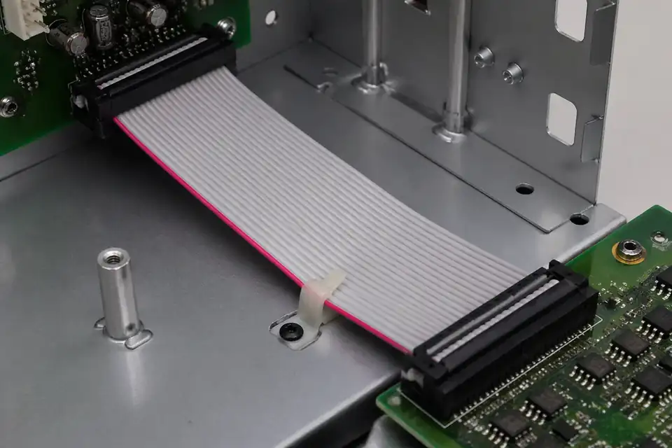
Ribbon IDC flat cable assembly inside a routine electronics chassis
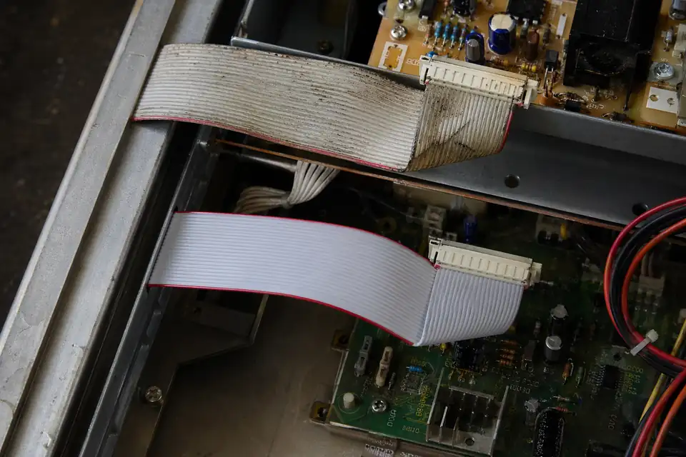
Ribbon IDC replacement-project hardware fit context
Ribbon IDC Build Definition
Release the assembly only after the connector drawing, ribbon construction, conductor registration, exit direction, and termination process describe one buildable interface. Treat family literature as selection evidence and keep every dimensional or performance value tied to the exact connector and cable part numbers.
| NO | Definition item | Required release input | Engineering decision | Controlled evidence |
|---|---|---|---|---|
| 01 | Mating interfaces | Endpoint connector part numbers and mating drawings | Confirm contact count, gender, orientation, and compatible counterpart | Approved manufacturer drawings |
| 02 | Connector geometry | Pitch, position count, row arrangement, and body style | Match the termination body to the intended ribbon geometry | Exact connector revision |
| 03 | Ribbon cable | Cable part number, conductor spacing, conductor construction, and insulation | Approve the cable and connector as a defined termination combination | Cable specification and sample |
| 04 | Pin-one convention | Connector view, circuit numbering, and ribbon stripe assignment | State the viewing direction on every pinout and work instruction | Released pin map |
| 05 | Cable exit | Exit side, connector orientation, and any fold location | Preserve access and avoid loading the termination during installation | Assembly drawing |
| 06 | Polarization | Key, notch, latch, and mating access constraints | Select features that prevent the credible reversed-mating condition | Interface review record |
| 07 | Termination process | Approved press, applicator, setup, cover, and inspection method | Lock tooling and setup to the released connector-cable combination | Process instruction |
| 08 | Strain management | Clamp, strain-relief feature, service loop, and pull direction | Keep installation and service loads out of the terminated conductors | Installation drawing |
First-Party Engineering References
- TE Connectivity AMP-LATCH Ribbon Connectors
Use for the AMP-LATCH family selection and termination concept only; confirm every geometry, material, rating, and tooling detail against the exact TE part documentation.
- IPC/WHMA-A-620E Release Notice
Use as context for cable-and-wire-harness process and acceptance planning; the public release is not an IDC design specification or evidence that a supplier or assembly is certified.
Ribbon Termination Failure Review
Review defects from the conductor path outward: registration at the contacts, cover seating, connector orientation, cable damage, and installed strain. The control plan must detect a defective termination before a correctly mapped but mechanically weak assembly reaches final equipment.
| NO | Failure mode | Likely cause | Design or process control | Detection evidence |
|---|---|---|---|---|
| 01 | Off-by-one conductor registration | Ribbon edge or first conductor was not located to the connector datum | Provide an unambiguous pin-one datum and controlled loading method | Setup check plus point-to-point test |
| 02 | Incomplete mass termination | Press setup, cable construction, or cover seating is incorrect | Qualify the exact tooling stack and define seating acceptance | Visual inspection and electrical test |
| 03 | Reversed connector orientation | Work instruction view or stripe convention is ambiguous | Show connector view, exit direction, and stripe together | First-off comparison and continuity result |
| 04 | Uneven cover seating | Nonparallel loading or damaged termination hardware | Control press alignment and reject distorted components | Seating inspection against approved sample |
| 05 | Cut or notched conductor | Poor cable handling or incompatible termination geometry | Protect ribbon edges and approve the connector-cable pairing | Magnified inspection and continuity check |
| 06 | Conductor fatigue at connector exit | Cable is bent, pulled, or clamped at the termination boundary | Add strain management and define a neutral installation route | Installed-condition inspection and retention test |
Ribbon Assembly Release Verification
Verification combines document reconciliation, first-off process evidence, full electrical screening, and installation checks. Test limits belong in the project control plan so the results can be traced to the released connector, cable, tooling setup, and assembly revision.
| NO | Verification activity | Method | Acceptance basis | Release record |
|---|---|---|---|---|
| 01 | Source-document reconciliation | Compare the bill of materials and drawing to exact manufacturer documents | Parts, revisions, pitch, positions, and mates agree | Design review checklist |
| 02 | First-off termination review | Inspect registration, body condition, cover seating, and exit direction | Matches the approved drawing and workmanship criteria | First-article inspection |
| 03 | Point-to-point continuity | Test every populated circuit against the released netlist | No open circuits, misroutes, or cross-connections under the specified test conditions | Serialized test result |
| 04 | Circuit isolation | Check unintended connections between defined circuit groups | Meets project-specific isolation limits | Electrical test report |
| 05 | Mating and polarization | Mate the assembly to the approved mating parts or validated interface fixtures in the intended orientation | Full engagement without unintended reverse mating | Fit-check record |
| 06 | Retention and strain response | Apply the project-defined load in the credible service direction | No displacement, damage, or electrical discontinuity | Qualification report |
| 07 | Production setup approval | Confirm tooling identity, setup parameters, and approved sample at changeover | Setup matches the controlled process instruction | Line clearance and setup log |
Engineering Capability
Standard ribbon IDC engineering fixes pitch, pin count, Pin 1, connector viewing direction, keying, cable exit, strain relief, and route clearance before termination. Cross-over or reordered conductors require a separate mapping table.
Engineering Capability
Review route path, connector references, and local fit together for the ribbon IDC build.
Quality and Verification Highlights
Watch local-fit zones, connector exits, and route transitions specific to ribbon IDC installs.
Evidence Chain
Controlled pitch and straight-through pin-order drawing
Tie both connector views, Pin 1, pitch, pin count, cable exit, route dimensions, and the active revision to one released drawing.
IDC termination and installed-fit record
Record the approved tooling or connector instructions, termination checks, fixing method, and installed clearance for the standard ribbon build.
Sample-to-batch correspondence
Keep sample approval, continuity results, batch labels, and shipment records tied to the same straight-through drawing revision.
Files and Batch Support
Ribbon IDC work has its own document layer around route and fitting boundaries. Cross-family file control, batch traceability, and certification practice are summarised in the Related Capability Pages.
Ribbon IDC route and fitting-boundary records
Capture the route path, local fit, and installation-space limits that are specific to the ribbon IDC build so later structural differences can be traced back to the right layer of change.
Certifications / Records Visuals
IMAGES · 04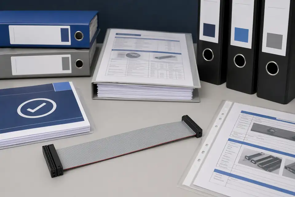
Ribbon IDC harness sample with quality-system and compliance documents
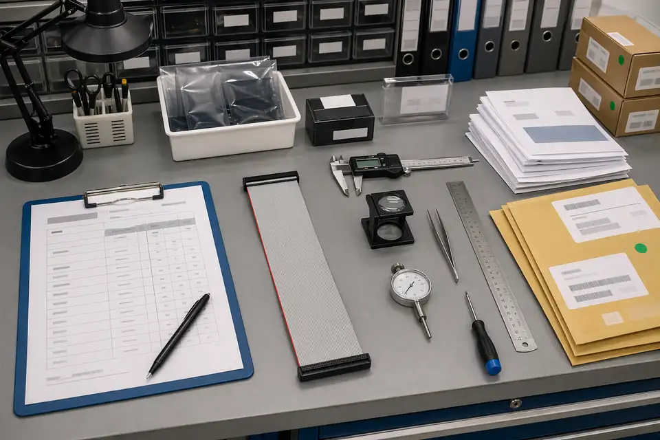
Ribbon IDC sample approval, inspection, or verification record context with released sample correspondence
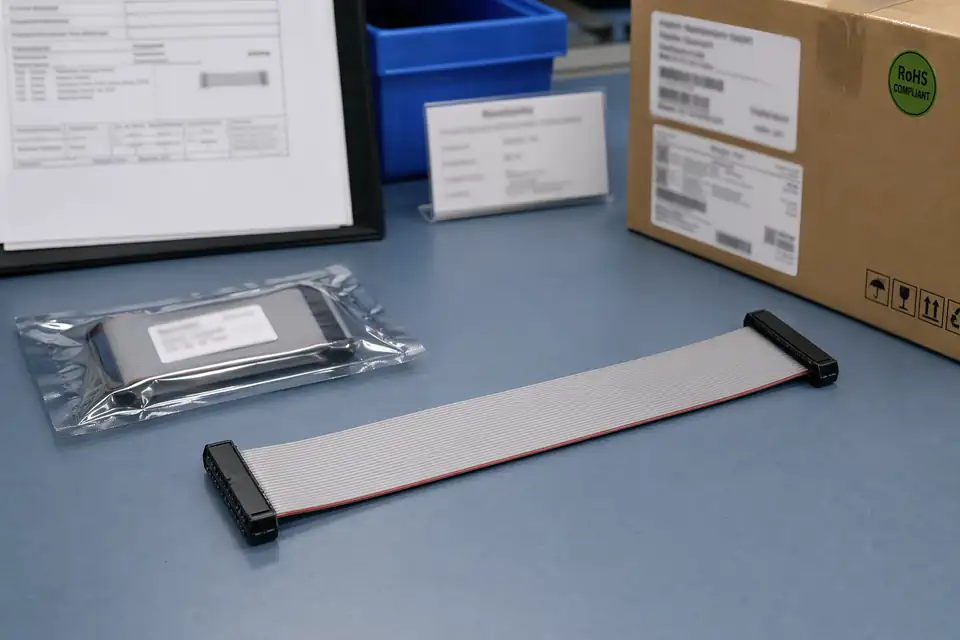
Ribbon IDC batch label, carton mark, or released-version file scene for revision-linked execution support

Ribbon IDC document-control and released-basis correspondence scene with harness sample and controlled records together
FAQ
Can you work from an old ribbon IDC sample?
Yes. Old parts help, but pitch, pin count, route fit, and the current device version still need to be checked before the sample can represent the released build.
What is the minimum input for a ribbon IDC quotation?
Send connector references, pitch, pin count, route context, project stage, and expected quantity.
Why do standard IDC configurations still need route review?
Because connector orientation, local fit, and version boundaries often decide whether a standard format actually works in the real product.
Can one ribbon IDC configuration cover several versions?
Sometimes, but only if pitch, pin count, and route boundaries stay inside the same approved definition.
Can review start before the full drawing package is complete?
Yes. Early review can start from connector references, pitch, pin count, and route context, then tighten as the file package becomes clearer.