Technical Reference · CUSTOM-PIN-MAPPING
Custom Pin-Mapping IDC
Custom Pin-Mapping IDC Cable Assemblies
For IDC projects that need non-standard line logic, connection mapping, and controlled release scope
EDPcable supports IDC assemblies with cross-over conductors, reordered pins, breakout branches, daisy-chain nodes, or other non-standard connection logic. Release starts with connector end views, Pin 1, keying, a point-to-point mapping table, node or branch order, route dimensions, and a continuity netlist. A standard straight-through ribbon build belongs to the ribbon-IDC direction.
Quick Links
QUICK ACCESSStart with the sections closest to the project structure, interface requirements, and validation scope.
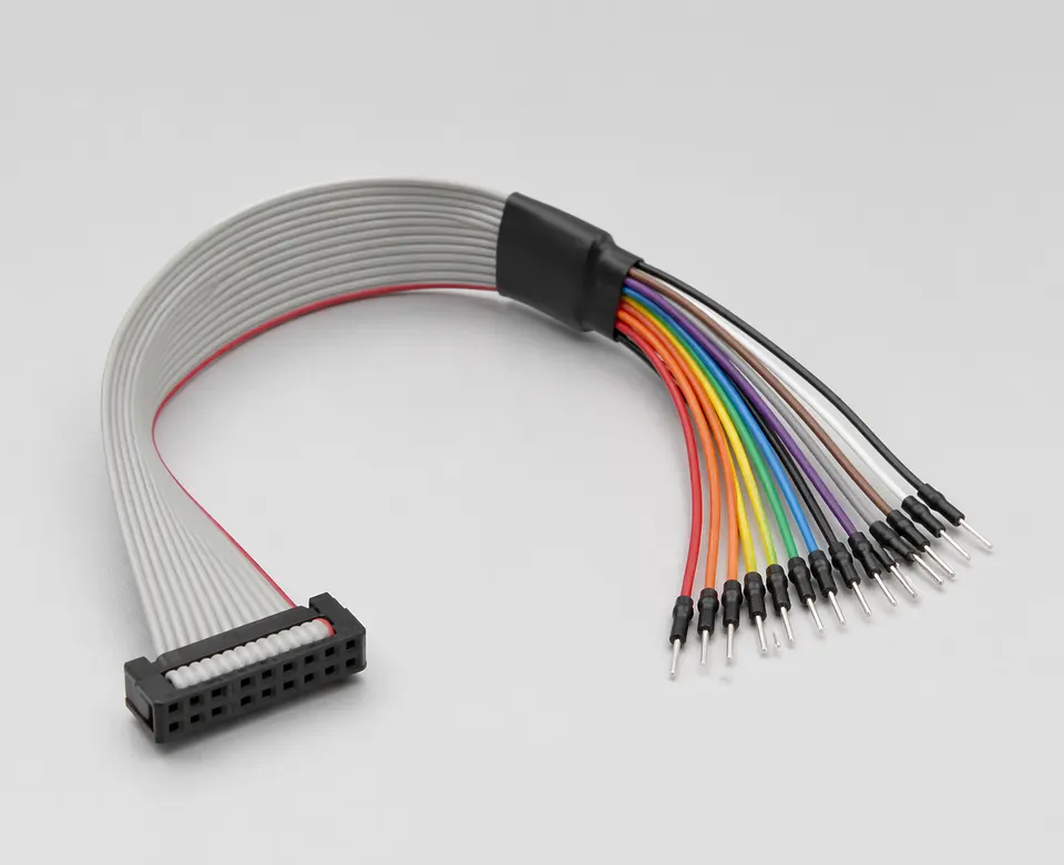
Custom Pin-Mapping Product Overview
Custom pin-mapping IDC programs work best when the mapping logic is already known and the next review can focus on connector form, route fit, local installation, and version scope before sampling.
| NO | Item | Typical Range or Meaning |
|---|---|---|
| 01 | Common Use | Non-standard line order, custom interface logic, project-specific IDC interconnects |
| 02 | Key Inputs | Pin mapping, connector form, route path, version scope, installation context |
| 03 | Engineering Focus | Line-order accuracy, route validity, structure boundaries, release logic |
| 04 | Quality Focus | Repeatable IDC termination, mapping accuracy, file-linked version control |
| 05 | Release Basis | Connector references, mapping logic, route notes, and version-controlled records |
Engineering Inputs
Use these items as first-round review inputs so the discussion does not rely on the page label alone.
Send connector references or clear mating photos.
Include pin mapping, route path, and key local-fit notes.
Add connection-logic notes and any installation-space limits.
Describe project stage, expected quantity, and timing target.
Explain any version boundaries that affect the mapping.
Customer Pain Points
Custom pin-mapping IDC projects often sound straightforward once the product or route category is known. In real RFQ and sample work, delays usually appear in route fit, structure judgement, and revision control rather than in the label alone.
| NO | Customer Pain Point | Typical Risk | What Needs Early Confirmation |
|---|---|---|---|
| 01 | Product design issues | The connector path, structure, or local fit still does not truly match the custom pin-mapping IDC build, so the sample becomes only a temporary reference | Connector references, route path, structure boundaries, and installation space |
| 02 | Product quality issues | Execution, local fit, or batch consistency drifts across repeated custom pin-mapping IDC builds | Structure definition, quality focus, and revision linkage |
| 03 | Lead-time issues | Missing inputs force repeated sample loops and slow quotation, release, and batch timing | Connector data, route notes, project stage, quantity, and timing |
| 04 | After-sales issues | It becomes difficult to tell whether the issue came from structure, revision, or installed conditions | Drawing files, sample approval records, batch labels, and shipment records |
| 05 | Complaint-handling issues | Revision boundaries are unclear, so issue tracing stays slow | Revision confirmation, batch correspondence, and inspection records |
| 06 | Pricing issues | A broad request turns into repeated pricing changes once real fit constraints surface | Structure complexity, material expectations, quantity, and delivery boundaries |
Product Applications
Custom pin-mapping assemblies are defined by the released point-to-point connection table, connector viewing direction, Pin 1, branch order, and continuity netlist rather than by cable length alone.
| NO | Application Scene | Scene Focus | Typical Concerns |
|---|---|---|---|
| 01 | Project-specific interface logic | non-standard line order and released mapping control | line-order accuracy, drawing correspondence, and sample validity |
| 02 | Control-board custom harnesses | installed route fit around non-standard mapping logic | connector direction, fixing method, and maintenance fit |
| 03 | Signal-distribution routes | multi-endpoint connection relationships | mapping boundaries, structure control, and issue tracing |
| 04 | Replacement programs | matching historical mapping to the active platform version | revision scope, usable boundaries, and after-sales handling |
| 05 | Sample-led validation projects | turning custom line logic into a released production basis | sample approval, batch consistency, and file linkage |
Application Scene Visuals
IMAGES · 05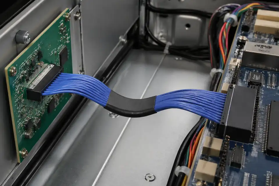
Custom pin-mapping IDC assembly in a control-board interface-conversion setup
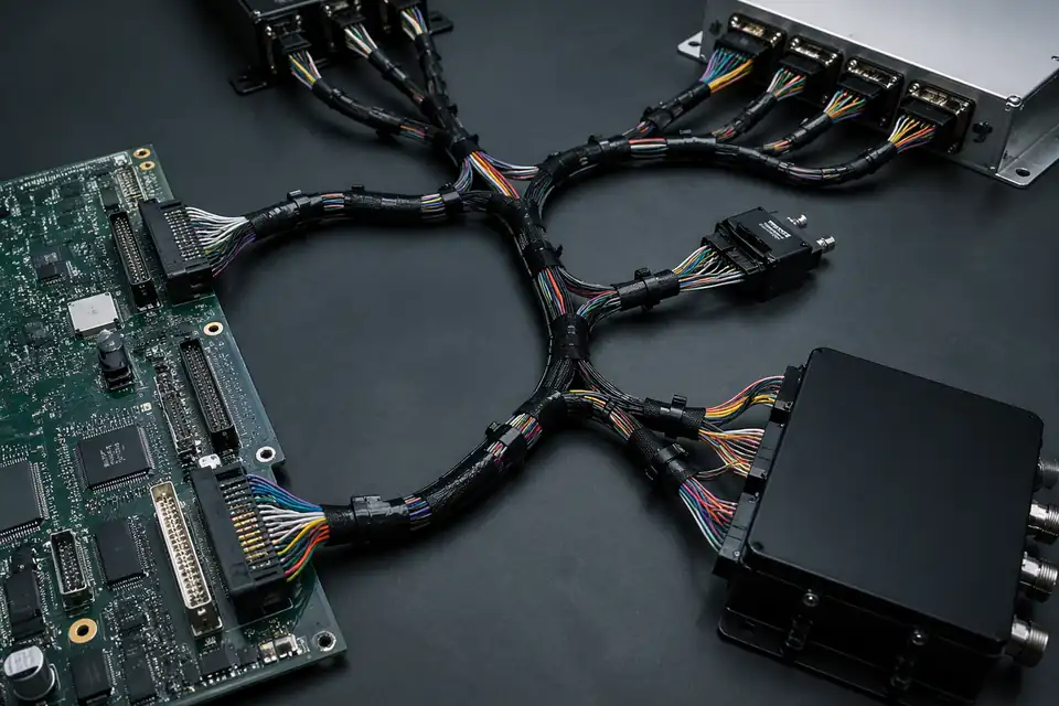
Custom pin-mapping IDC assembly linking multiple electronic modules
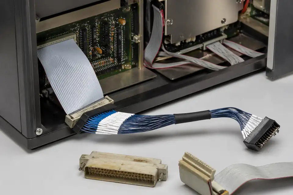
Custom pin-mapping IDC assembly in an old-part replacement context

Custom pin-mapping IDC assembly in a tailored multi-end wiring system
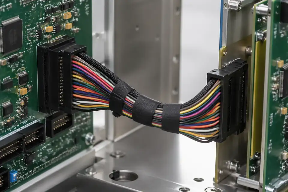
Custom pin-mapping IDC assembly in a special interface-matching project
Custom Mapping Release Matrix
A custom map is controlled by endpoint identity and viewing direction, not merely by a colored ribbon edge. Release one authoritative source-to-destination netlist that also resolves crossovers, unused positions, branches, connector orientation, and the revision used by the production test system.
| NO | Mapping element | Required definition | Release rule | Authoritative artifact |
|---|---|---|---|---|
| 01 | Endpoint identity | Unique reference for every connector and branch | Names must agree across schematic, drawing, label, and tester | Interface control document |
| 02 | Connector view | Mating-face or termination-face view for each endpoint | Place the view convention beside the circuit numbering | Controlled pinout drawing |
| 03 | Circuit map | Explicit source pin, destination pin, and net name | List every populated position; do not infer straight-through routing | Released netlist |
| 04 | Crossovers and folds | Conductor path changes required by endpoint orientation | Show how physical routing preserves the logical map | Assembly layout |
| 05 | Unused positions | Open, reserved, or future-use status | State the required test disposition for each unused or unpopulated connector position | Netlist notes |
| 06 | Branches or splices | Parent conductor, branch destination, and joint location | Identify each non-one-to-one topology as a controlled feature | Branch schedule |
| 07 | Pin-one marking | Ribbon stripe, connector mark, and label relationship | Make physical orientation consistent with the declared connector view | Marking detail |
| 08 | Revision linkage | Drawing, netlist, fixture program, and label-template revisions | Release them as one compatible configuration | Configuration index |
First-Party Engineering References
- IPC/WHMA-A-620E Release Notice
Use to frame cable-assembly process and acceptance controls; define the custom electrical map and all numeric test limits in project-controlled engineering documents.
- TE Connectivity AMP-LATCH Ribbon Connectors
Use only when the released assembly selects an AMP-LATCH family component; family-page statements do not establish the mapping, ratings, or compatibility of another IDC connector.
Custom Netlist Failure Review
Mapping errors often survive visual inspection because every connector can look properly terminated. The review therefore concentrates on ambiguous views, stale configuration data, non-straight-through circuits, branch circuits, and other exceptions, with independent electrical evidence as the principal escape control.
| NO | Failure mode | Error mechanism | Preventive control | Escape control |
|---|---|---|---|---|
| 01 | Mirrored endpoint map | One connector was numbered from the opposite viewing face | Declare the view beside each endpoint drawing | Independent netlist review and continuity test |
| 02 | Stale tester program | Fixture data was not updated with the released pinout | Link program checksum to assembly revision | Known-good and seeded-fault challenge plus configuration audit |
| 03 | Duplicated or omitted net | Manual transcription lost a position or reused a destination | Generate and review a complete endpoint-to-endpoint table | Automated map completeness check |
| 04 | Branch destinations exchanged | Identical connectors or labels allow branch substitution | Use unique endpoint identifiers and keyed routing where feasible | Branch-specific point-to-point test |
| 05 | Connector-end reversal | The physical build was rotated while the logical map remained unchanged | Control stripe, exit direction, and connector orientation together | First-off physical comparison |
| 06 | Correct wiring with wrong identification | Label template revision diverged from the harness configuration | Release labels inside the same configuration set | Scan-to-record and endpoint audit |
Custom Mapping Verification Plan
Verification starts with an independent interpretation of the interface documents and ends with a tester result tied to the same revision. A representative mate and a known-standard challenge are included so fixture orientation or program errors do not merely reproduce the design mistake.
| NO | Verification activity | Execution method | Acceptance criterion | Evidence retained |
|---|---|---|---|---|
| 01 | Independent map review | Second reviewer derives endpoint mapping from the interface documents | Derived map agrees with the released netlist | Signed review record |
| 02 | Configuration alignment check | Compare drawing, netlist, tester program, and label-template identifiers | All identifiers belong to the approved release set | Configuration report |
| 03 | Complete continuity test | Exercise every defined source-to-destination circuit | Each circuit resolves only to its assigned endpoint | Serialized tester output |
| 04 | Isolation test | Check forbidden connections and defined unused positions | No unintended connection at project-defined limits | Electrical test log |
| 05 | Branch identity check | Test each branch through its final label and connector | Physical endpoint and logical endpoint agree | Branch verification sheet |
| 06 | Known-good and seeded-fault challenge | Run approved known-good and seeded-fault samples through the fixture | Tester detects each represented fault and passes the standard | Fixture validation record |
| 07 | Mating-orientation check | Fit representative approved mates and compare pin-one orientation | Physical mating preserves the released circuit view | First-article report |
| 08 | Identification audit | Scan or read all assembly and endpoint labels | Labels resolve to the correct drawing and netlist revision | Traceability record |
Engineering Capability
Custom mapping review fixes both connector end views, Pin 1, keying, every point-to-point connection, branch or node order, and the continuity netlist before sample termination. Route dimensions remain a separate installed-fit check.
Engineering Capability
Review connector end views, Pin 1, keying, point-to-point mapping, node order, and the test netlist as one release package.
Quality and Verification Highlights
Check connector orientation, conductor order, branch labels, node spacing, and netlist results against one released revision.
Evidence Chain
Controlled point-to-point mapping table
Record both connector end views, Pin 1, keying, every point-to-point connection, branch order, and the active revision in one released package.
Mapping and continuity verification record
Verify conductor order, shorts, branch identification, and node spacing against the approved netlist before installed-fit approval.
Mapped sample and batch correspondence
Keep the approved mapped sample, continuity output, batch label, and shipment record linked to the same connection-table revision.
Files and Batch Support
Custom pin-mapping IDC work has its own document layer around route and fitting boundaries. Cross-family file control, batch traceability, and certification practice are summarised in the Related Capability Pages.
Custom pin-mapping IDC route and fitting-boundary records
Capture the route path, local fit, and installation-space limits that are specific to the custom pin-mapping IDC build so later structural differences can be traced back to the right layer of change.
Certifications / Records Visuals
IMAGES · 04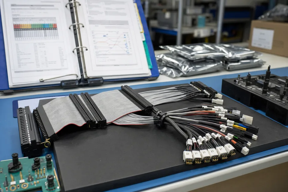
Custom IDC harness sample with controlled pin-mapping records
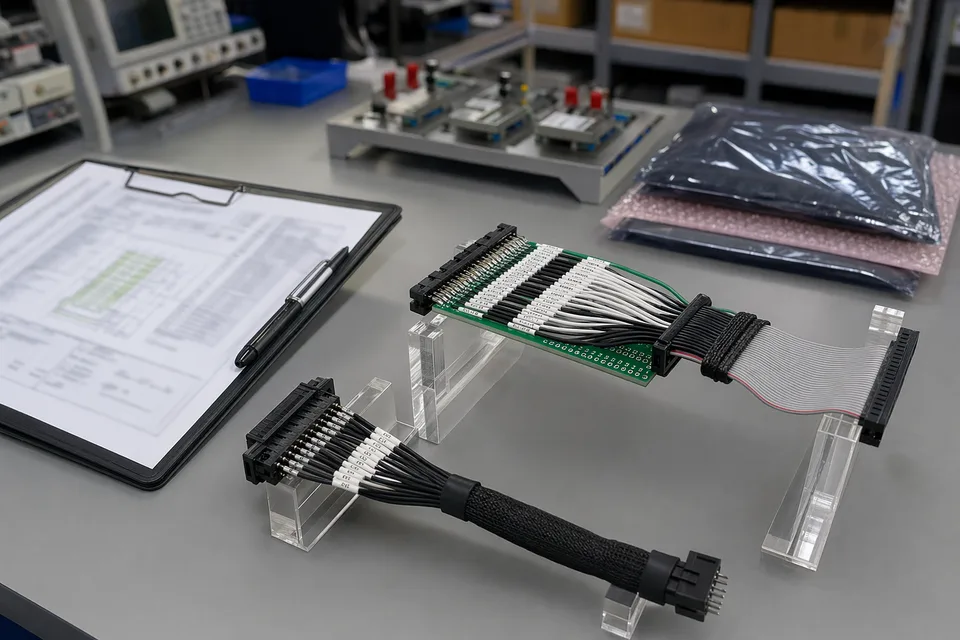
Custom IDC breakout harness with released pin-map and sample-approval records
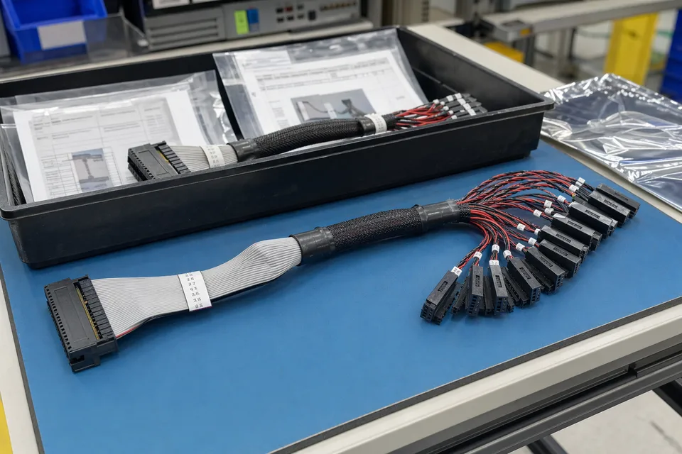
Custom IDC revision-controlled sample archive tray with wire-map harness and document sleeves
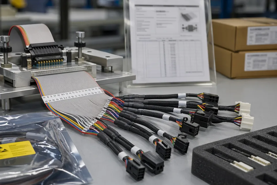
Custom IDC traceability record scene linking pin-mapping sample, batch card, and connector lot context
FAQ
Can you work from an old custom-mapping sample?
Yes. Old parts help, but the current mapping logic, route fit, and platform version still need to be checked before the sample can represent the released build.
What is the minimum input for a custom-mapping quotation?
Send connector references, pin mapping, route context, project stage, and expected quantity.
Why does custom mapping still need route review?
Because line logic may be correct on paper while route fit, local clearance, or connector orientation still fail inside the real product.
Can one custom mapping cover multiple product versions?
Sometimes, but only if line order, route context, and version scope stay inside the same approved definition.
Can review start before the full drawing package is complete?
Yes. Endpoint pin tables, named viewing directions, the draft netlist, and a list of crossover or branch exceptions support an early mapping review before the assembly print is final.