Technical Reference · PITCH-OPTIONS
IDC Pitch Selection
Custom IDC Cable Assemblies for 1.27mm, 2.0mm, and 2.54mm Pitch Options
For IDC projects where pitch choice, connector fit, cable format, and pin mapping need to be reviewed together
EDPcable supports custom IDC cable assemblies where the RFQ is still choosing between 1.27mm, 2.0mm, 2.54mm, and nearby IDC pitch formats. Pitch is only the entry point. Connector family, cable format, pin count, line order, route path, fixing method, and maintenance space should be checked together before the sample or quote boundary is treated as fixed.
Quick Links
QUICK ACCESSStart with the sections closest to the project structure, interface requirements, and validation scope.
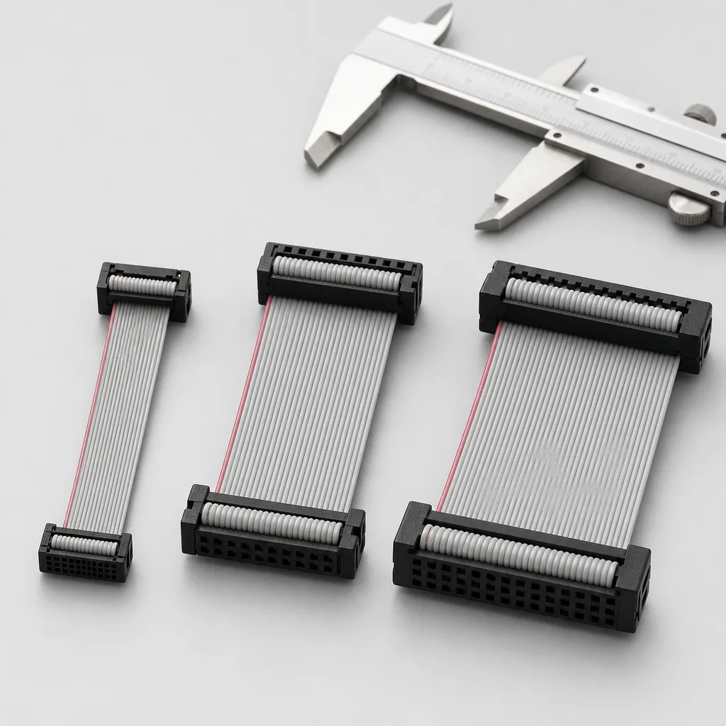
IDC Pitch Options Product Overview
Best fit for IDC projects where pitch selection is still part of engineering and sourcing judgement. The review connects 1.27mm, 2.0mm, or 2.54mm choice to connector fit, cable format, pin mapping, route space, and release evidence.
| NO | Item | Typical Range or Meaning |
|---|---|---|
| 01 | Common Pitch Options | 1.27mm, 2.0mm, 2.54mm, and nearby IDC formats subject to connector availability |
| 02 | Typical Cable Formats | Ribbon cable, discrete IDC harnesses, short board links, cabinet or module routes |
| 03 | Key Inputs | Pitch target, connector reference, pin count, pin mapping, cable format, route path |
| 04 | Engineering Focus | Connector fit, cable exit direction, line order, strain relief, installed clearance |
| 05 | Release Basis | Pitch and connector confirmation, mapping logic, route notes, and revision-linked records |
Engineering Inputs
Use these items as first-round review inputs so the discussion does not rely on the page label alone.
Send connector references or note whether 1.27mm, 2.0mm, or 2.54mm is currently preferred.
Include pin count, pin mapping, cable format, route length, and cable exit direction.
Add installation limits, maintenance space, fixing method, and any strain-relief needs.
State whether the project is new development, replacement, validation, or repeat order.
List sample quantity, batch quantity, timing target, and active revision boundaries.
Customer Pain Points
IDC pitch-option projects often sound straightforward once the product or route category is known. In real RFQ and sample work, delays usually appear in route fit, structure judgement, and revision control rather than in the label alone.
| NO | Customer Pain Point | Typical Risk | What Needs Early Confirmation |
|---|---|---|---|
| 01 | Product design issues | The connector path, structure, or local fit still does not truly match the IDC pitch-option build, so the sample becomes only a temporary reference | Connector references, route path, structure boundaries, and installation space |
| 02 | Product quality issues | Execution, local fit, or batch consistency drifts across repeated IDC pitch-option builds | Structure definition, quality focus, and revision linkage |
| 03 | Lead-time issues | Missing inputs force repeated sample loops and slow quotation, release, and batch timing | Connector data, route notes, project stage, quantity, and timing |
| 04 | After-sales issues | It becomes difficult to tell whether the issue came from structure, revision, or installed conditions | Drawing files, sample approval records, batch labels, and shipment records |
| 05 | Complaint-handling issues | Revision boundaries are unclear, so issue tracing stays slow | Revision confirmation, batch correspondence, and inspection records |
| 06 | Pricing issues | A broad request turns into repeated pricing changes once real fit constraints surface | Structure complexity, material expectations, quantity, and delivery boundaries |
Product Applications
IDC pitch selection connects the mating-connector drawing to conductor geometry, pin count, line order, cable exit, termination tooling, installed clearance, and revision scope.
| NO | Application Scene | Scene Focus | Typical Concerns |
|---|---|---|---|
| 01 | Compact module links | smaller pitch selection with limited local space | connector availability, handling tolerance, and route exit |
| 02 | Industrial control wiring | maintainable IDC routes inside cabinets or equipment | pitch readability, cable bend, and service access |
| 03 | Board-to-board extensions | short IDC paths with fixed mating orientation | pin count, connector direction, and line-order clarity |
| 04 | Ribbon cable replacements | matching old IDC pitch and pin count to current parts | near-match connector risk and old sample ambiguity |
| 05 | Multi-version equipment | one pitch decision across several device revisions | usable scope, mapping differences, and file control |
Application Scene Visuals
IMAGES · 05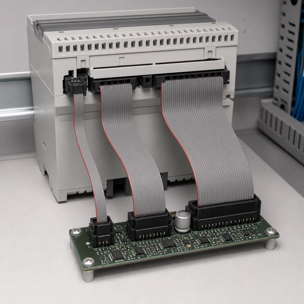
Compact-module IDC link line-art with a smaller-pitch ribbon connector in limited local space
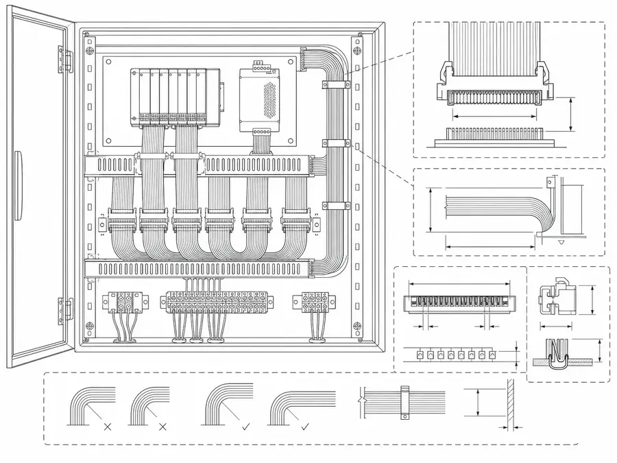
Industrial-control IDC wiring line-art with maintainable ribbon routes inside a cabinet and pitch selection
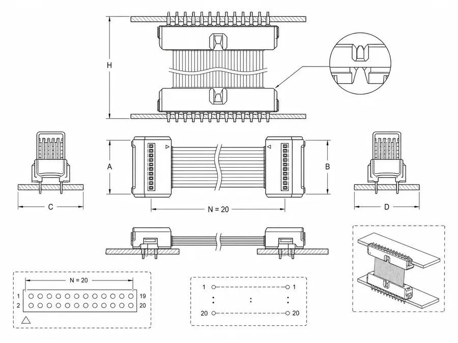
Board-to-board IDC extension line-art with short ribbon paths, a fixed mating orientation, and pin count
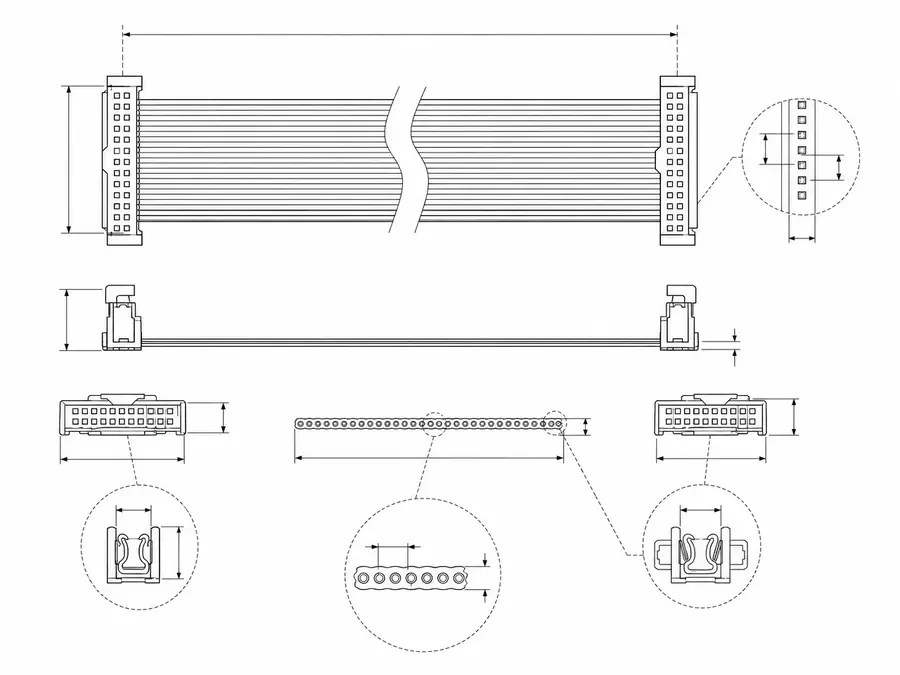
Ribbon-cable replacement line-art matching old IDC pitch and pin count to a current part
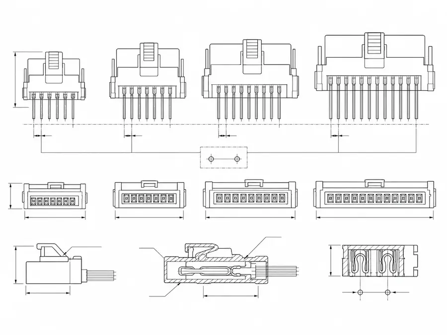
Multi-version equipment IDC layout line-art with one pitch decision across several device revisions
IDC Pitch Selection Matrix
Treat nominal pitch labels as candidate interface categories, not interchangeable build instructions. Selection must resolve to an exact connector family, matching cable geometry, approved tooling, mating access, and product documentation before any pitch description is released to purchasing or production.
| NO | Selection factor | Comparison input | Decision rule | Required proof |
|---|---|---|---|---|
| 01 | Exact connector family | Manufacturer series and orderable part number | Compare documented variants rather than nominal pitch alone | Current product drawing |
| 02 | Nominal pitch | Connector contact spacing and intended ribbon spacing | Require explicit geometry compatibility | Connector and cable specifications |
| 03 | Position count | Circuit demand, reserved contacts, and available variants | Select a documented position count with controlled unused circuits | Pin-allocation review |
| 04 | Cable construction | Conductor size, spacing, insulation, and ribbon width | Approve the cable for the exact termination interface | Cable data and termination trial |
| 05 | Termination system | Connector cover, press, applicator, and process window | Confirm production has controlled compatible tooling | Tooling and process specification |
| 06 | Mating features | Header style, keying, latch, and orientation | Prevent a mechanically possible but electrically wrong mate | Mating-interface drawing |
| 07 | Packaging envelope | Body size, cable exit, keep-outs, and service clearance | Verify the chosen family in the installed assembly model | Envelope and fit review |
| 08 | Lifecycle and supply continuity | Lifecycle status, approved alternates, and tooling ownership | Qualify substitutions as new interfaces rather than silent pitch matches | Approved-source record |
First-Party Engineering References
- Molex Picoflex Connectors
Use for the exact Picoflex family and its manufacturer-published 1.27 mm category only; verify dimensions, ratings, positions, cable, mates, and tooling for the selected part number.
- Hirose HIF3B Series
Use for the exact HIF3B family and its manufacturer-published 2.54 mm category only; do not transfer series attributes or compliance statements to a different IDC family or completed assembly.
Pitch Selection Failure Review
The dominant risk is a plausible-looking substitution that shares a pitch label while changing cable fit, mating geometry, tooling, or polarization. Review purchasing descriptions and production setup together so a nominal match cannot bypass exact-series qualification.
| NO | Failure mode | Why it occurs | Engineering prevention | Verification signal |
|---|---|---|---|---|
| 01 | Lookalike pitch substitution | Commodity description omits family and part number | Control the exact manufacturer name and orderable part number | Receiving check to approved documentation |
| 02 | Ribbon geometry mismatch | Nominal connector pitch is assumed to prove cable compatibility | Specify the approved connector-cable combination | Termination trial and section review if required |
| 03 | Wrong termination tooling | Similar bodies are processed with an unqualified press setup | Bind tooling identity and setup to each selected family | Setup verification and first-off inspection |
| 04 | Incorrect mating half | Pitch and position count match but keying or header style differs | Release both sides of the interface together | Representative mating check |
| 05 | Accumulated centerline error | Cable conductors are forced into incompatible contact locations | Compare complete connector and cable geometry | Registration inspection across the full width |
| 06 | Uncontrolled discontinued variant | Supply pressure drives an undocumented family change | Require interface, tooling, and qualification review for alternates | Change-control audit |
Pitch Option Qualification Plan
Qualify the selected option as a complete interface rather than a centerline measurement. The evidence package must connect exact source documents to incoming parts, termination setup, installed mating, electrical results, and any approved alternate.
| NO | Verification activity | Method | Pass condition | Controlled output |
|---|---|---|---|---|
| 01 | Part-document cross-check | Compare orderable parts with current connector, cable, and mate documents | All selected variants and revisions are compatible | Source review record |
| 02 | Geometry confirmation | Inspect or measure pitch, positions, ribbon registration, and key features | Observed features agree with exact released drawings | Incoming or first-article report |
| 03 | Termination trial | Build representative samples with production tooling and cable | Consistent seating without visible conductor or body damage | Process qualification record |
| 04 | Mating fit check | Mate samples to the approved counterpart in the installed orientation | Full engagement, correct polarization, and required access | Fit-check report |
| 05 | Electrical screen | Test every circuit for mapping, continuity, and required isolation | Results meet the project netlist and test limits | Serialized test data |
| 06 | Retention assessment | Apply the project-defined loads at the connector and cable in the specified directions | No damage, displacement, or intermittent circuit | Qualification result |
| 07 | Tooling release | Verify tooling identity, setup, inspection points, and operator instruction | Production controls reproduce the qualified samples | Approved process sheet |
| 08 | Alternate-part qualification | Repeat affected interface and process checks for any alternate | No alternate is accepted by pitch description alone | Change approval package |
Engineering Capability
Engineering value in an IDC pitch review comes from matching the connector drawing, pin count, conductor geometry, cable format, exit direction, termination tooling, and installed clearance before release.
Engineering Capability
Review route path, connector references, and local fit together for the IDC pitch-option build.
Quality and Verification Highlights
Watch local-fit zones, connector exits, and route transitions specific to IDC pitch-option installs.
Files and Batch Support
IDC pitch-option work has its own document layer around route and fitting boundaries. Cross-family file control, batch traceability, and certification practice are summarised in the Related Capability Pages.
IDC pitch-option route and fitting-boundary records
Capture the route path, local fit, and installation-space limits that are specific to the IDC pitch-option build so later structural differences can be traced back to the right layer of change.
Certifications / Records Visuals
IMAGES · 04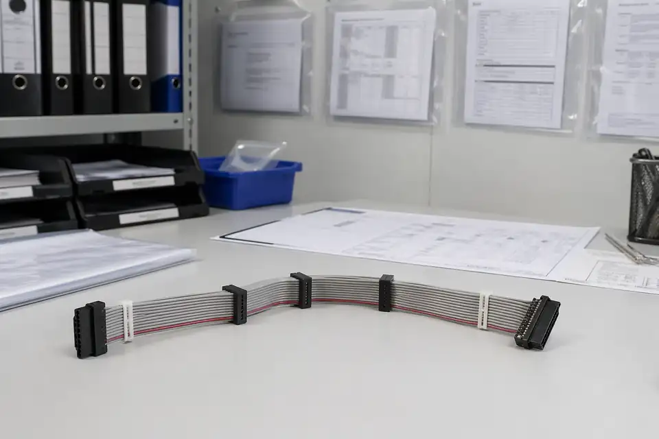
IDC cable assembly document-control scene with records secondary to the harness and connector set
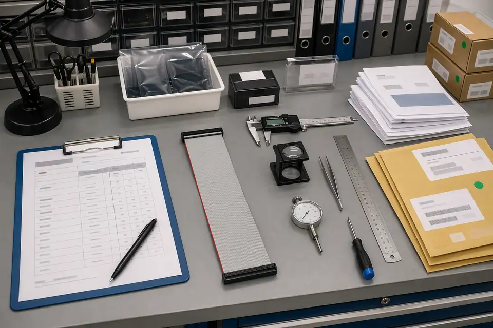
IDC sample approval and released-sample correspondence scene with controlled records
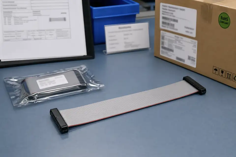
IDC revision-linked carton mark, batch label, or released-version file scene with harness support context
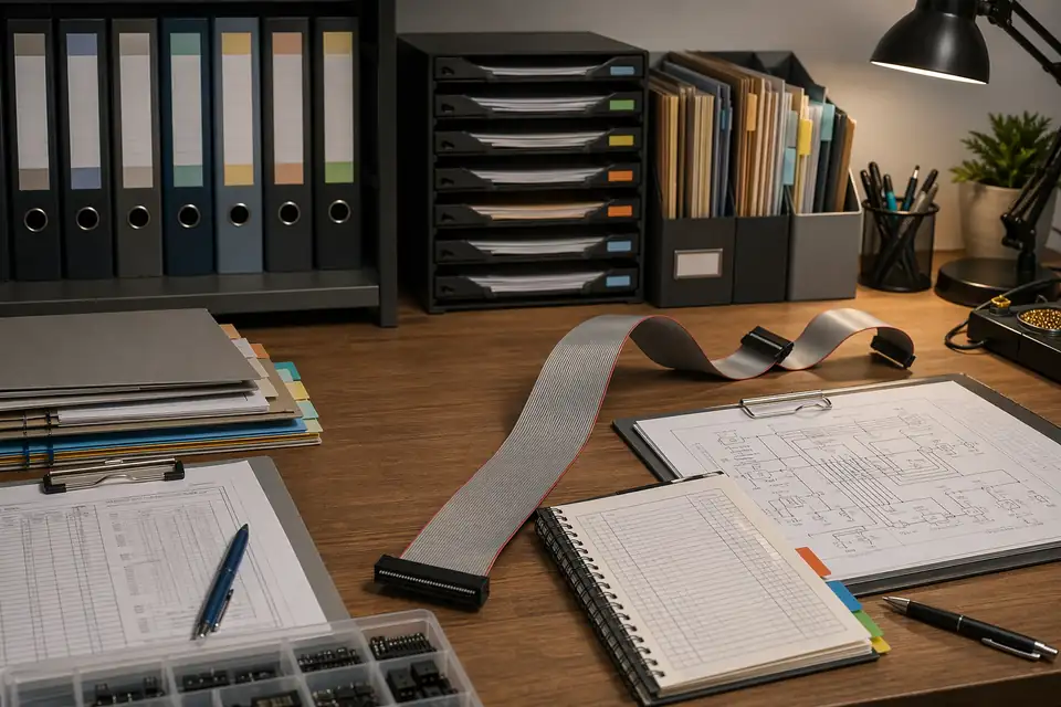
IDC controlled records and released-basis correspondence scene with folders, files, and the harness together
FAQ
Which IDC pitch should I choose first?
Start from connector availability, local space, pin count, cable format, and service requirements. 1.27mm saves space, 2.54mm is usually easier to handle, and 2.0mm often sits between the two.
Can you quote if I only know the old sample?
Yes. Send photos, pitch measurements if available, pin count, and device context. The old sample still needs connector and mapping confirmation before release.
Is pitch enough for an IDC quotation?
No. Pitch should be paired with connector reference, pin count, pin mapping, cable type, route path, quantity, and timing.
Can one IDC pitch cover several equipment versions?
Sometimes, but only if connector family, pin mapping, cable format, route geometry, and revision scope stay inside the same approved definition.
Can you compare 1.27mm, 2.0mm, and 2.54mm during RFQ?
Yes. A comparison is practical when the installation space, pin count, cable format, and handling requirements are clear enough to judge tradeoffs.