Technical Reference · INDUSTRIAL-CONTROL
Industrial-Control IDC
Custom IDC Cable Assemblies for Industrial Control Systems
For cabinet wiring, control boards, and stable line-order routing inside industrial equipment
EDPcable supports IDC assemblies for control cabinets, control boards, I/O modules, and internal equipment links where service access is part of the design. Confirm pin mapping, keying, connector orientation, cable exit, strain relief, fixing points, service loop, maintenance clearance, and the continuity netlist against the equipment drawing. Pitch selection and non-standard mapping remain separate specification decisions.
Quick Links
QUICK ACCESSStart with the sections closest to the project structure, interface requirements, and validation scope.
Industrial-Control IDC Product Overview
Industrial-control IDC programs work best when the equipment context is already clear and the next review can focus on line logic, route fit, maintenance access, and revision scope before sampling.
| NO | Item | Typical Range or Meaning |
|---|---|---|
| 01 | Typical Use | Cabinet wiring, control-board links, I/O modules, backplane extension |
| 02 | Key Inputs | Pin mapping, connector form, route path, structure type, revision scope |
| 03 | Engineering Focus | Line-order clarity, route stability, maintenance fit, release boundaries |
| 04 | Quality Focus | Repeatable IDC termination, stable routing, file-linked batch control |
| 05 | Release Basis | Mapping logic, route notes, maintenance limits, and revision-controlled records |
Customer Pain Points
Industrial-control IDC projects often sound simple because the application context is already clear. In real RFQ and sample work, delays usually appear in line logic, route fit, maintenance access, and revision control rather than in pitch alone.
| NO | Customer Pain Point | Typical Risk | What Needs Early Confirmation |
|---|---|---|---|
| 01 | Product design issues | The connector form or route path still does not truly fit the cabinet or module space, so the sample becomes only a temporary reference | Connector references, route path, maintenance space, and structure boundaries |
| 02 | Product quality issues | IDC termination, line logic, or route execution drifts across batches | Structure definition, quality focus, and revision linkage |
| 03 | Lead-time issues | Missing route and maintenance inputs force repeated sample loops and delay release | Connector data, route notes, project stage, quantity, and timing |
| 04 | After-sales issues | It becomes difficult to tell whether the issue came from line logic, revision, or installed conditions | Drawing files, sample approval records, batch labels, and shipment records |
| 05 | Complaint-handling issues | Revision boundaries are unclear, so issue tracing stays slow | Revision confirmation, batch correspondence, and inspection records |
| 06 | Pricing issues | A broad IDC request turns into repeated pricing changes once real fit and maintenance constraints surface | Structure complexity, quantity, and delivery boundaries |
Product Applications
Industrial-control IDC is not only a cable format. It usually appears in products where line logic, route fit, maintenance access, and revision scope all matter. The five scenes below are the most common application contexts.
| NO | Application Scene | Scene Focus | Typical Concerns |
|---|---|---|---|
| 01 | Cabinet wiring | Route path and maintenance space stay more sensitive | Line-order clarity, fixing method, later service |
| 02 | Control-board to I/O links | Interface consistency matters more | Pin mapping, connector direction, batch consistency |
| 03 | Backplane extension paths | Structure boundaries are more complex | Length, multi-way logic, replacement conditions |
| 04 | Internal equipment flat-cable routes | Repeat delivery and after-sales both matter | Structure discipline, file correspondence, timing |
| 05 | Replacement programs | Old versions and current hardware conditions coexist | Release boundaries, traceability, usable scope |
Application Scene Visuals
IMAGES · 05
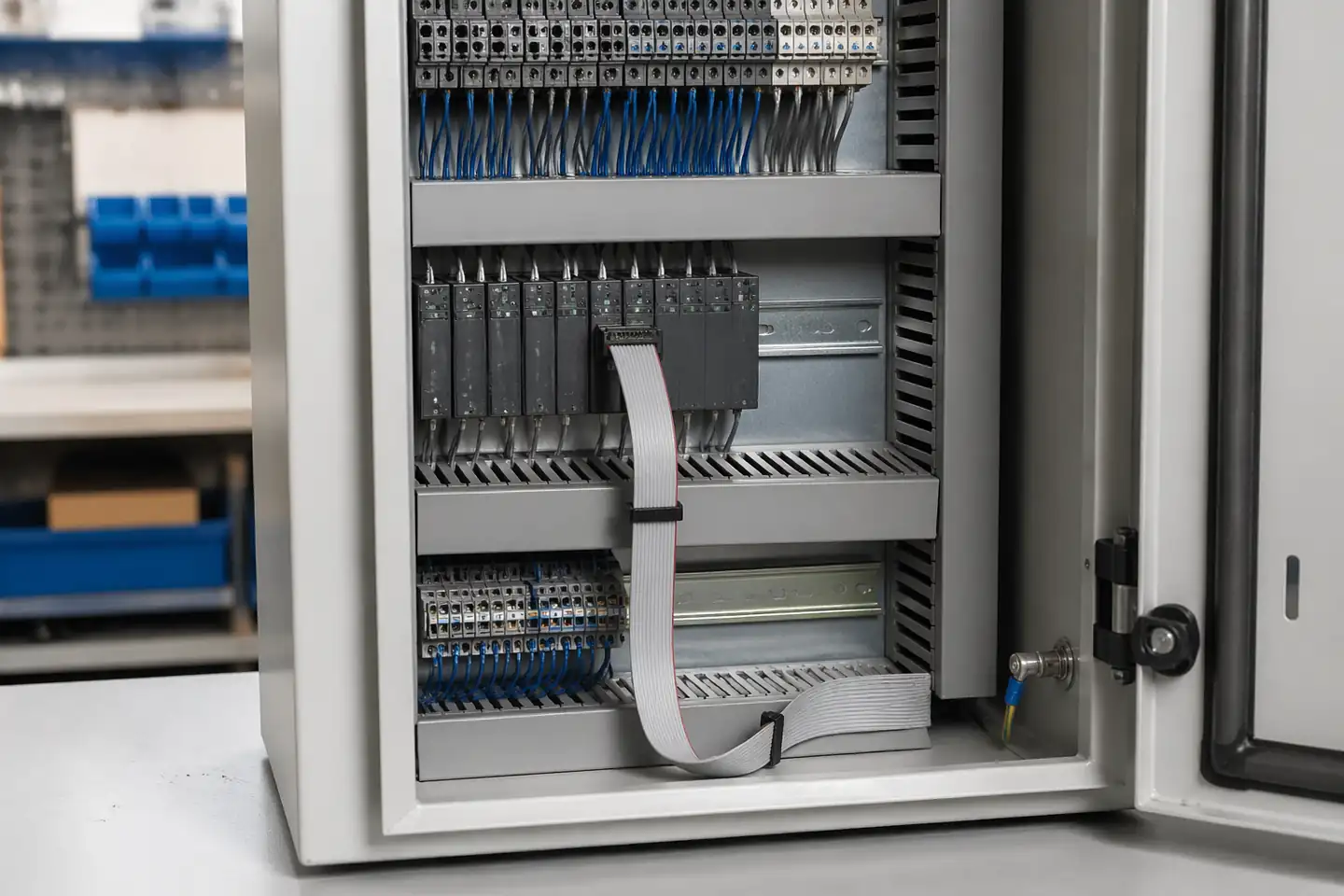
IDC ribbon assembly in industrial control cabinet routing context
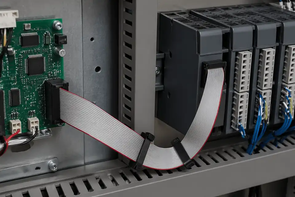
IDC assembly connecting a control board to I/O modules inside an industrial cabinet
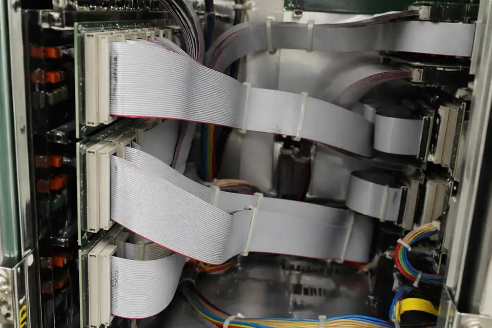
IDC backplane extension interconnect inside industrial equipment
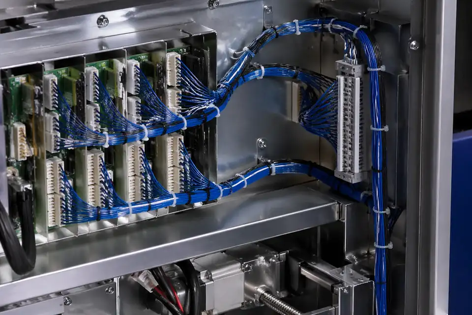
IDC wiring system inside machine equipment with repeat-supply-friendly layout
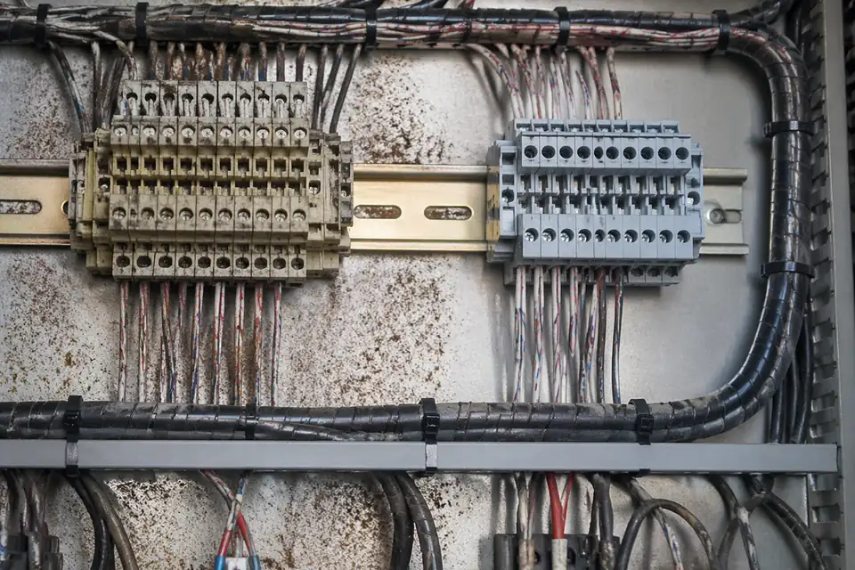
IDC replacement-project context inside industrial control equipment
Industrial Control Harness Definition
Define the IDC harness in its cabinet and service context: exact endpoints, circuit allocation, route, clamp locations, replacement access, environmental limits, and identification all influence whether the assembly remains correct after installation and maintenance.
| NO | Control-harness input | Definition required | Engineering disposition | Release artifact |
|---|---|---|---|---|
| 01 | Control endpoints | Exact board, module, and connector interfaces | Resolve mating parts, orientation, and access at both ends | Interface drawing |
| 02 | Circuit allocation | Signal, supply, return, spare, and reserved positions | Approve a complete pin map with stated unused-pin behavior | Controlled netlist |
| 03 | Polarization strategy | Keys, latches, connector uniqueness, and nearby lookalike ports | Reduce credible service mis-mating through physical and visual controls | Mis-mating review |
| 04 | Cabinet route | Bend locations, edge crossings, service loop, and moving access panels | Keep the ribbon clear of abrasion, pinch points, and forced folds | Installation layout |
| 05 | Strain management | Clamp type, position, contact surface, and load direction | Support the cable without crushing conductors or loading terminations | Clamp detail |
| 06 | Project environment | Specified temperature, vibration, contaminants, and enclosure conditions | Select materials and qualification exposures from documented requirements | Environmental requirement set |
| 07 | Service identification | Harness identifier, endpoint labels, pin-one cues, and revision | Make replacement identity readable in the installed cabinet | Marking specification |
| 08 | Replacement boundary | Approved spare, field procedure, and interface revision compatibility | Prevent a mechanically fitting but electrically incompatible replacement | Service configuration record |
First-Party Engineering References
- IPC/WHMA-A-620E Release Notice
Use for cable-and-wire-harness process and acceptance planning; cabinet routing, environment, electrical limits, and required acceptance class must come from the project's controlled requirements.
- TE Connectivity AMP-LATCH Ribbon Connectors
Use only for an AMP-LATCH component selected by exact part number; confirm its mate, tooling, ratings, and application limits in the applicable manufacturer documentation.
Cabinet Harness Failure Review
Separate manufacturing defects from installation and service hazards. A harness that passes bench continuity can still fail when routed across a panel edge, compressed by a clamp, pulled during module removal, or replaced with a visually similar revision.
| NO | Failure mode | Installed cause | Preventive control | Detection approach |
|---|---|---|---|---|
| 01 | Service mis-mating | Adjacent ports accept a similar connector or labels are obscured | Use interface differentiation and durable endpoint identification | Service-task fit review |
| 02 | Ribbon chafe | Cable crosses a sharp panel edge or moving hardware | Add protected routing, edge treatment, or controlled support | Installed-route inspection |
| 03 | Clamp-induced conductor damage | Clamp pressure or edge geometry concentrates load | Define approved clamp hardware, position, and closure | First-install inspection and electrical test |
| 04 | Termination overload during removal | Technician pulls the cable because connector access is poor | Provide grip access, service loop, and removal instructions | Representative maintenance trial |
| 05 | Wrong replacement revision | A spare fits mechanically but carries a different map | Tie service part identity to interface revision | Scan or configuration check before installation |
| 06 | Environmental incompatibility | Actual enclosure exposure exceeds the documented material or interface basis | Translate project environment into component and qualification requirements | Requirement trace and exposure testing where specified |
Industrial Installation Verification
Release evidence must include the installed route and a realistic maintenance action in addition to production electrical screening. Environmental or vibration testing is added only when the project requirement defines the exposure and acceptance criteria.
| NO | Verification activity | Representative condition | Acceptance basis | Evidence |
|---|---|---|---|---|
| 01 | Interface and keying check | Mate each endpoint among nearby cabinet interfaces | The specified interfaces engage fully, and the defined mis-mating attempts are prevented or detected | Installation fit record |
| 02 | Installed-route inspection | Install the harness in representative cabinet hardware with covers and moving parts | No pinch, chafe, forced bend, or inaccessible release feature | Photo-backed route review |
| 03 | Complete electrical test | Test the finished harness after termination and marking | All circuits meet released mapping and project limits | Serialized tester result |
| 04 | Clamp and retention check | Apply installation and service loads through approved supports | No cable damage, movement, or electrical interruption | Mechanical verification report |
| 05 | Maintenance simulation | Remove and reinstall the connected module using the field procedure | The technician can release, identify, and reconnect the harness without applying unintended cable load or making a connection error | Service trial record |
| 06 | Environmental exposure | Apply only the project's specified temperature or contaminant condition | Meets documented post-exposure visual, mechanical, and electrical criteria | Qualification report |
| 07 | Vibration assessment | Test the representative installed support arrangement when required | No intermittent circuit, disengagement, or unacceptable wear | Project-specific test report |
| 08 | Identification and traceability | Read labels in the installed position and resolve the build record | Harness and endpoints identify the correct service configuration | Final inspection record |
Engineering Capability
Engineering value in an industrial-control IDC page comes from aligning line logic, route fit, and maintenance access before release. Cross-family engineering review, drawing control, and documentation practice are covered in the Related Capability Pages below.
Engineering Capability
Review pin mapping, route path, and maintenance limits together in the real equipment context.
Treat connector direction and fixing logic as part of the same release definition.
Quality and Verification Highlights
Focus on repeatable IDC termination, stable route execution, and clean line-order control.
Watch branch points, connector exits, and service-space fit closely in installed builds.
Evidence Chain
Sample Approval and Installed-Fit Records
Use sample confirmation records and route-review notes to show whether the approved sample actually matches the maintenance space, fixing logic, and installed conditions being quoted.
Control-Panel Mapping and Service Records
Industrial-control IDC assemblies need a release package that keeps pin mapping, polarity, keying, branch order, strain relief, and service access aligned with the target controller or I/O revision.
Pin-map and orientation drawing
Show connector viewing direction, Pin 1, keying, any crossover or breakout, branch lengths, and end identification on the released assembly drawing.
Continuity and installed-fit approval
Link continuity results and the approved sample to the intended header orientation, service loop, strain-relief position, and enclosure access condition.
Controller-revision identification
Use part and revision labels that distinguish controller, I/O board, pin-map, and branch variants before they reach maintenance or final assembly.
Service-ready packing and labels
Protect keyed connectors and strain-relief features during shipment, and keep end labels readable where technicians depend on them for replacement.
Certifications / Records Visuals
IMAGES · 04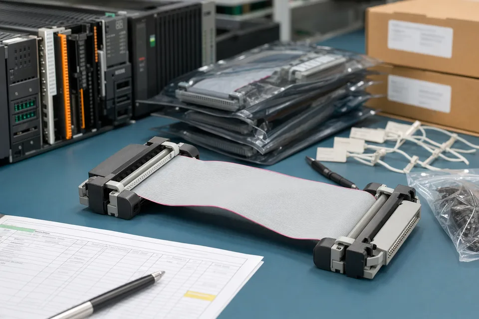
Industrial-control IDC batch record scene with harness sample and connector lot traceability context
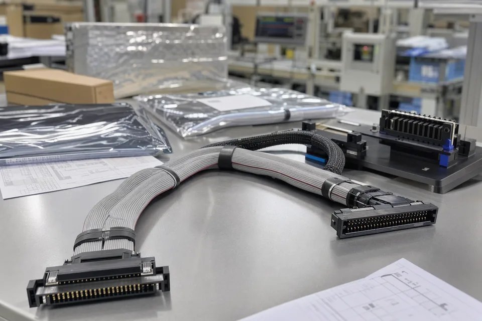
PLC IDC ribbon harness with controlled release documents
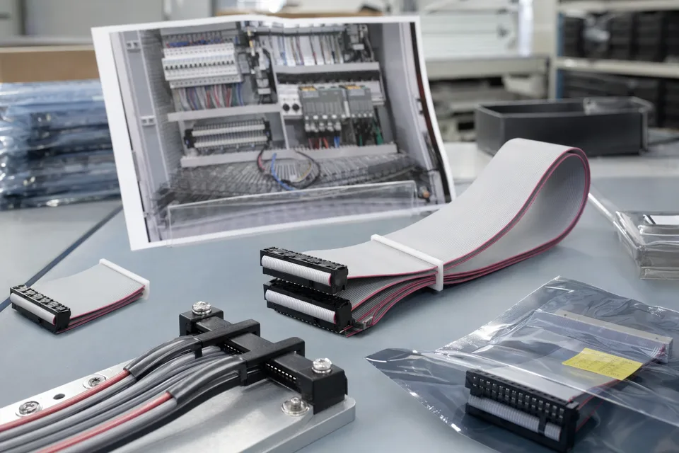
Industrial-control IDC sample approval archive with cabinet-fit support material and harness sample
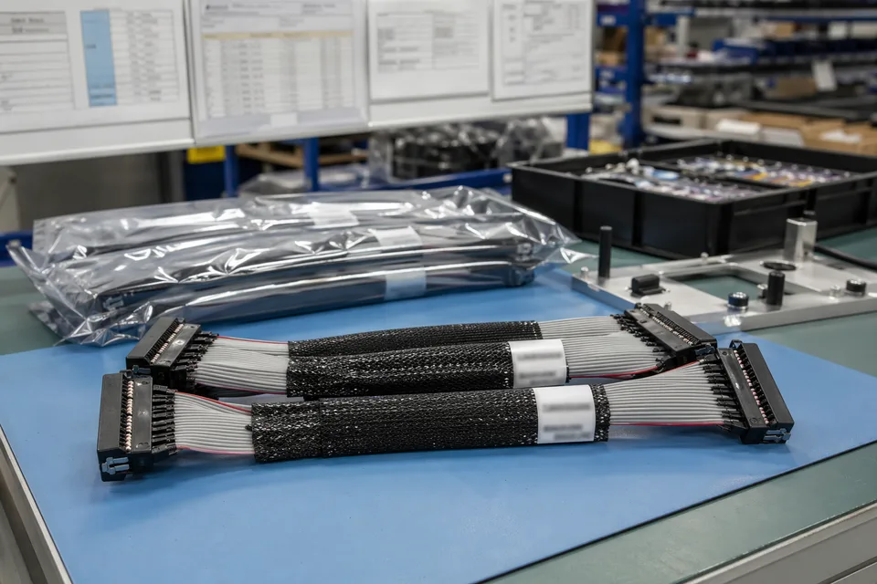
Industrial IDC revision and batch traceability scene with records, labels, and harness support context
FAQ
Can you review an industrial-control project from an old sample?
Yes. Old parts help, but the current route path, maintenance fit, and platform revision still need to be checked before the sample can represent the released build.
What is the minimum input for an industrial-control IDC quotation?
Send connector references, pin mapping, route context, project stage, and expected quantity.
Why do industrial-control projects need more than pitch or connector form?
Because route fit, maintenance access, and revision scope often decide whether the cable can actually be released and supported over time.
Can one IDC assembly serve several control versions?
Sometimes, but only if line logic, route geometry, and revision scope stay inside the same approved definition.
Can review start before the full drawing package is complete?
Yes. The cabinet endpoint list, circuit allocation, preliminary route, clamp locations, and service-removal path provide enough information to identify industrial-control harness risks early.