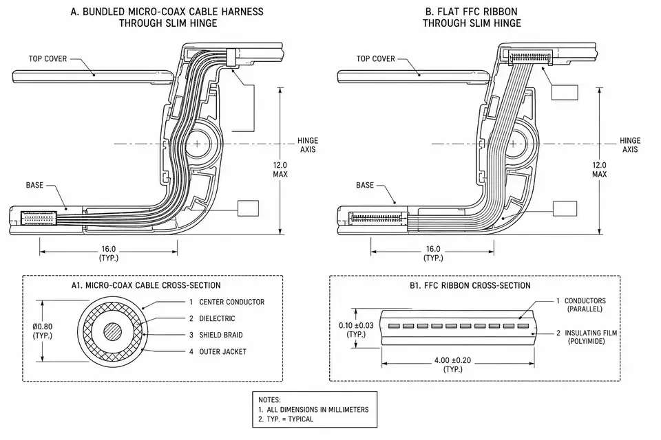
The Same Space Problem
Getting a signal from A to B doesn't sound hard. The path is what's hard: an 8mm-thick enclosure, a battery and a heat spreader in the way, and one segment that follows a hinge through a daily open-and-close cycle. FFC and micro-coax were both born for this kind of cramped space, but their approaches are opposite — FFC flattens the conductors out, micro-coax makes each conductor tiny and bundles them. Different solutions, different sweet spots.
What FFC Does Well, and Where It Stops
FFC is rolled flat copper conductors laid in parallel and laminated into a ribbon. Its advantages are direct:
- Thin — 0.1mm-class thickness slips through the gap between battery and housing
- Cheap — the cable is a standard commodity, ZIF connectors terminate without solder
- Volume-friendly — consistency comes from the material itself
The limits are just as clear. All conductors run parallel and unshielded, so crosstalk and emissions can only be managed by spacing and ground lines. Bending works along one axis only — to turn corners in two directions, FFC has to resort to folding; folded routing solves part of it, but path freedom remains limited.
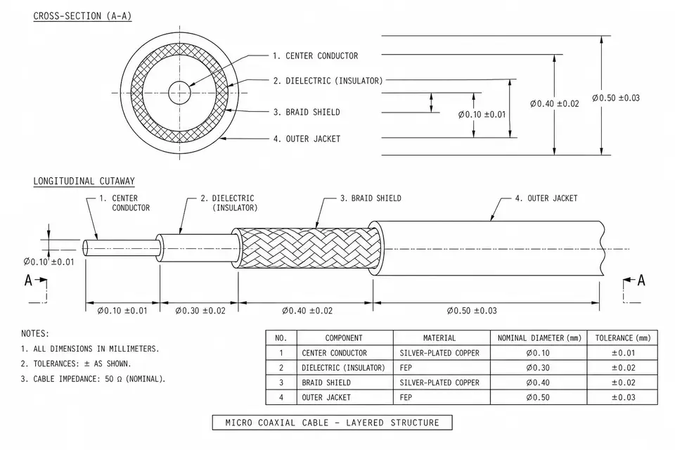
What Micro-Coax Does Well, and What It Costs
Micro-coax is the opposite philosophy: every signal line is a complete coaxial structure — center conductor, dielectric, shield, jacket — at gauges of 36–46 AWG, so that dozens of lines bundle into a few millimeters of diameter.
Per-line shielding means crosstalk and EMI are pinned down structurally; RF and high-speed differential signals travel safely. A round bundle has no preferred bending direction — hinges, gimbals and 3D detours are all fair game — and dynamic flex life is easier to engineer high than in flat laminated structures.
The price is cost and process: the cable is more expensive, and termination must strip an extremely fine layered coax structure. At the 0.25mm pitch tier, termination makes real demands on equipment and inspection.
Side by Side
| Dimension | FFC | Micro-coax |
|---|---|---|
| Shielding | None overall (ground layers optional) | Per-line individual shield |
| High-speed / RF | Mostly low-to-mid speed | Its home ground |
| Bending | Single axis, fold-to-fit | Any direction, good dynamic flex |
| Space shape | Flat gaps | Round bundle through holes, detours |
| Connector ecosystem | ZIF, enormous choice | Dedicated series, narrower |
| Cost | Low | High |
What Real Devices Are Choosing
Mapping the abstract dimensions onto real hardware makes it concrete. AR/VR headsets are micro-coax's most typical home turf: camera and display data rates are high, the housing is curved, and the harness threads a 3D path around optics — the AR/VR micro-coax harness page describes what these builds look like. UAV gimbal cameras are similar: the video link hates interference, and the cable moves with the gimbal continuously (see UAV / drone harnesses).
FFC's home turf is stacked construction: printer and scanner carriages, board-to-board links inside TVs and monitors, laptop keyboards and touchpads — high-volume flat interconnects. In between sits the laptop display hinge: thin and folding daily. The FFC camp answers with hinge flex cable rated specifically for bend cycles; the micro-coax camp answers with fine bundles. Both have mass-production track records — the tiebreaker is the device's thickness budget and EMI margin.
How to Choose — and Why the Answer Is Often "Both"
Classifying by signal beats classifying by device. RF (antennas) and high-speed serial (camera, display) lines that fear interference get the micro-coax budget; power, backlight and touch control lines that don't care ride FFC. Open up a real device and you'll often find both harnesses working side by side — not a compromise, just money spent where it matters.
If the whole machine has one interconnect and the space is a purely flat gap, FFC alone is enough. Conversely, with a complex path, sensitive signals and a hinge to cross, go straight to micro-coax and save yourself the EMC remediation loop later.