Why "Maximum Length" Is Not a Standard Number
This is one of the most common LVDS questions, and the honest answer starts with more questions: What is the pixel clock? How noisy is the route? How thick and stiff can the cable be? The LVDS signaling standard defines voltage swing and receiver tolerance. It does not promise a cable length. The same cable can run three meters in one design and fail at 40 cm in another because the four limiting variables are different.
Variable 1: Pixel Clock
Resolution and refresh rate set the pixel clock, and the pixel clock sets the data rate on each pair. Higher data rate means more high-frequency content, and high-frequency energy is what a cable attenuates first. The same construction goes farther at a lower clock. Dropping a design from 1920x1080 to 1280x800 can add a lot of margin. Among the four variables, this is usually the most direct one.
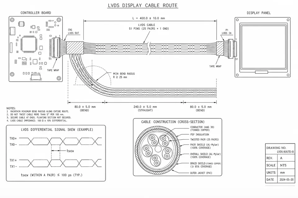
Variable 2: Skew
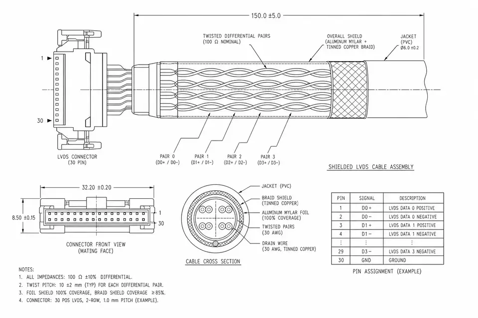
An LVDS display harness sends several data pairs in parallel and uses a clock pair as the timing reference. Three things need to line up: the two conductors inside each pair, the different pairs against each other, and the twist consistency along the run. Any mismatch narrows the receiver's sampling window. When that window disappears, the panel shows errors.
On the cable side, skew control comes from consistent twisting and matched cut lengths. This is one place where a display harness is not the same as a generic flat cable.
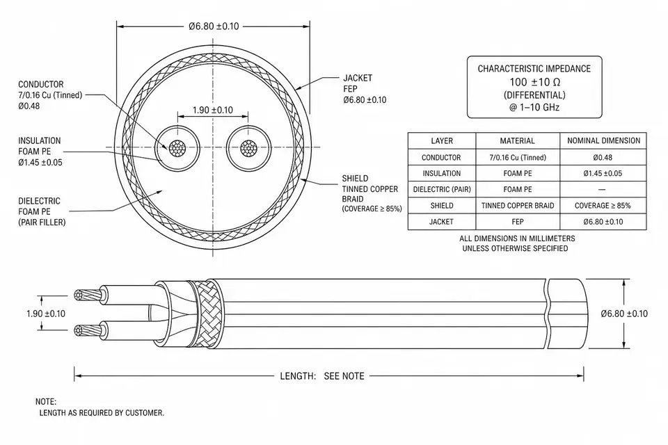
Variable 3: Attenuation and Wire Gauge
Signals lose energy as they travel through copper, and smaller conductors lose it faster. A 32 AWG construction may be fine at 0.5 m, while 2 m may push the design toward 28 AWG. Thicker wire brings its own cost: larger bend radius, stiffer routing and higher material cost. Length, diameter and flexibility form a real trade-off, not a free upgrade.
Variable 4: EMI Environment
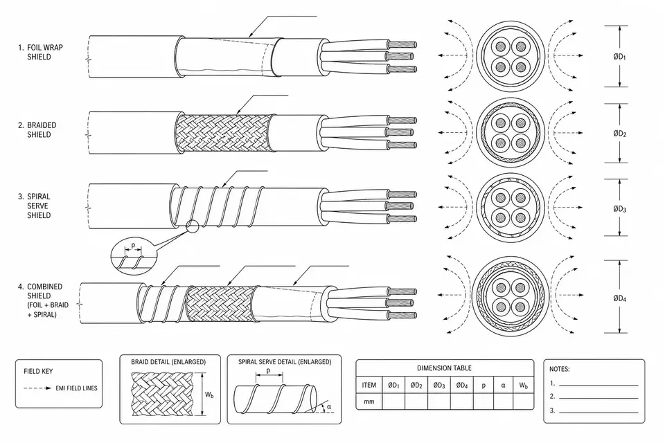
The first three variables decide how far the signal can travel on its own. EMI decides how much margin gets stolen on the way. A cable routed beside motors, inverters or power wiring can pick up noise that eats receiver margin quickly. Twisted pairs reject some common-mode noise; a harsher environment may need shielding. The shielding structures are covered in Cable Shielding Basics, and the application view is Shielded LVDS Routing.
Where This Question Shows Up
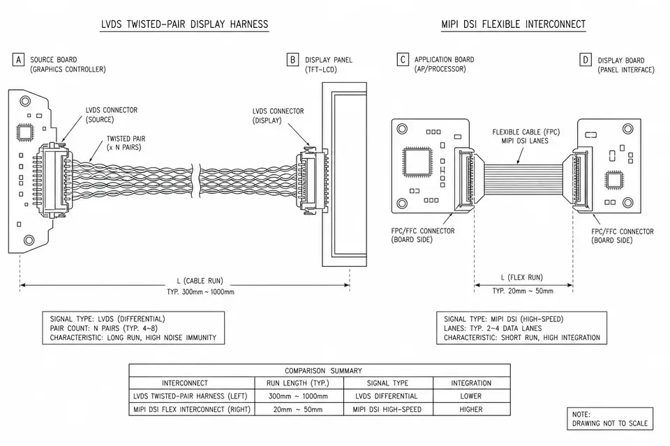
The same pattern appears in many projects. Industrial displays and retrofit systems put the control box in one place and the panel at the operator position, so industrial-monitor LVDS harnesses often land around a meter. Medical carts and articulated arms add hinge paths, lift columns and stricter routing constraints, as in medical monitor LVDS. Kiosks and gaming cabinets create the same problem because the main board and panel sit at opposite ends of a large enclosure.
In all of these cases, cable length is not designed first. It is what remains after the mechanical layout is chosen. The earlier the route, length and noise sources appear in the RFQ, the more margin the engineering team can keep.
Reference Ranges, and What to Do When They Are Not Enough
With all variables in view, useful reference ranges look like this: tens of centimeters are routine in a normal enclosure; 1-2 m is possible with moderate clocks, good twisted-pair construction and suitable shielding; beyond that, the project is in a designed-link zone.
If the run is simply too long, there are three practical choices. Lower the clock by reducing resolution or refresh rate. Change the link to a long-reach serializer/deserializer approach, often using coax or shielded twisted pair. Move the board closer to the panel and let a more suitable interface carry the long-distance part. Trying to force compensation into one ordinary LVDS cable is usually the expensive path.
For a real project, include resolution, refresh rate, route length and environment in the RFQ. The Board-to-Panel LVDS page lists the inputs needed for an engineering review.