Where Interference Comes From, and What a Shield Blocks
Motor starts and stops, switching power supplies, RF modules, the cable in the next slot — sources of electromagnetic interference are everywhere inside a machine. When that interference couples into a signal line, the mild version is occasional data errors; the severe version is a product that fails EMC testing outright. The working principle of a shield is simple: a conductive layer surrounds the conductors, the external field induces currents on the shield, and those currents drain to ground instead of coupling into the signal. It works both ways — the cable's own emissions stay locked inside, too.
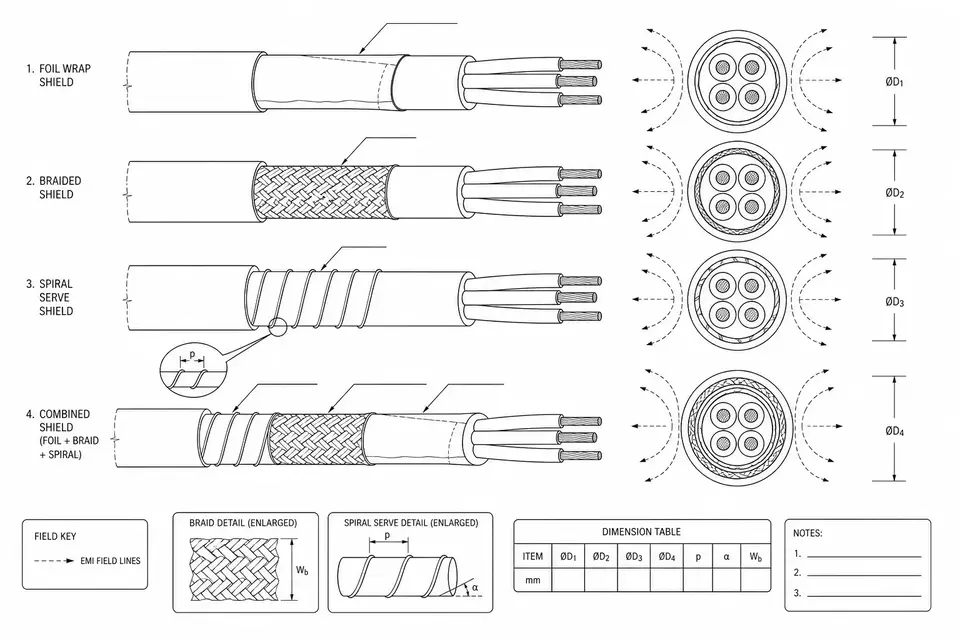
The remaining question is how that conductive layer is built. Three mainstream constructions, three very different personalities.
Foil: Full Coverage, Hates Flexing
A foil shield is a thin aluminum-polyester laminate wrapped longitudinally or spirally around the core. Its strength is coverage — effectively 100%, no gaps, so high-frequency interference finds no way in. It is also cheap and adds almost nothing to the cable diameter.
The weaknesses are equally clear: the foil layer is thin, and repeated flexing fatigues and cracks it; once cracks appear, high-frequency performance drops with them. Aluminum foil is also relatively resistive, so it cannot provide the low-impedance drain path that low-frequency interference demands. Foil suits fixed routing, not parts that move every day.
Braid: Tough and Flexible, but with Gaps
A braid shield is a woven sleeve of tinned copper strands. Mechanical strength is high — repeated flexing is no threat — and the copper cross-section is large, so it conducts well at low frequencies and can carry sizable induced currents.
Its built-in shortcoming is the gaps: a woven mesh can't reach full coverage. Dense braids manage up to 95%, ordinary ones 70–85%. The higher the frequency, the shorter the wavelength, and the easier it slips through the apertures.
Spiral: The Compromise for Very Thin Cables
A spiral (serve) shield winds copper strands in one direction around the core without interweaving. Its reason to exist is softness — cables too thin to accept a braided sleeve can still be shielded this way, and the single-wire shields in micro-coax are exactly this construction. The trade-off: flexing opens gaps between strands, so high-frequency performance trails braid, and trails foil further.
Combination Shields: Complementary Weaknesses
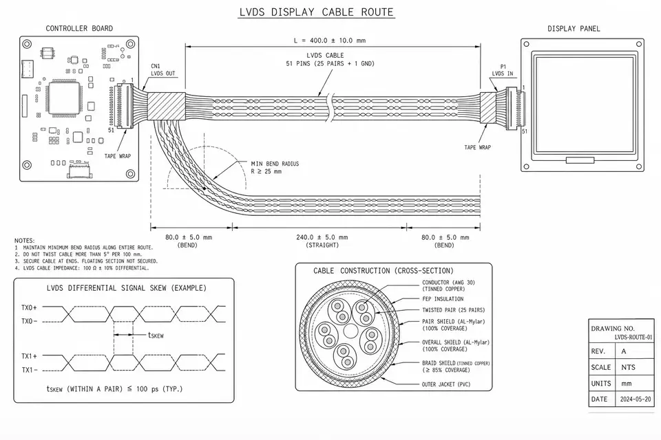
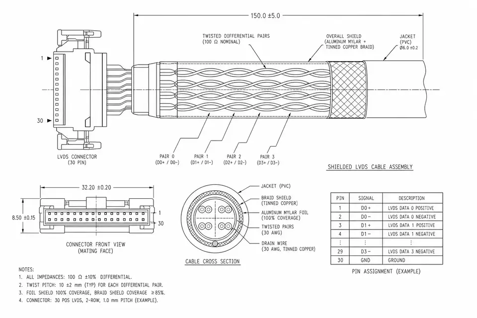
Stack the foil's "full coverage, blocks high frequencies" on the braid's "tough, good at low frequencies," and you get the foil-plus-braid combination shield. Their weaknesses are offset, which is why demanding video and data cables default to it. The High-Shielding Micro-Coax and Shielded LVDS Routing pages show combination shields in real product configurations.
Shielding Effectiveness, Drain Wires and EMC
Two terms are worth knowing when reading a shielded cable's spec sheet. Shielding effectiveness is measured in dB — the bigger the number, the cleaner the isolation. The same construction performs very differently across frequency bands, which is why "shielded" by itself says little; the question to ask is "how many dB at my interference frequency." A drain wire is a bare copper conductor running against the foil: foil itself is hard to terminate, so the drain wire carries the induced current to ground on its behalf — which is why foil-shielded cables almost always include one.
For the finished product, shielding ultimately serves EMC compliance — CE, FCC and similar emission and immunity limits. Medical equipment and industrial automation sites (cabinets dense with variable-frequency drives and servo drives) are the two environments where shielded cable works hardest, and where EMC remediation happens most. Going back to fix cable shielding after a failed EMC test is one of the most expensive remediation paths there is; designing the shield into the first prototype usually costs less than "run it bare, add shielding if it fails."
Termination Is Half the Battle
Choosing the right shield is only half the work. The shield must eventually connect to ground, and how it connects makes an enormous difference. A 360-degree termination — the shield clamped around its full circumference into the connector shell — preserves the shield's full performance. The lazy shortcut, twisting a pigtail and soldering it to ground, turns that pigtail into an antenna at high frequencies; tens of dB of shielding effectiveness can shrink to a remnant. When reviewing a quote or drawing for shielded cable, the termination method deserves its own line of questioning.
Do You Need a Shield? How to Judge
Ten centimeters of quiet in-enclosure cable: probably not. Cable leaving the enclosure, running alongside motors and power supplies, or a product facing CE / FCC radiated-emission limits: design the shield in. If you're unsure, write the routing environment into your RFQ — what's nearby, how long the run is, which certifications apply — and let the cable house do the math with you.