1. LVDS Isn't a Cable — It's a Way of Moving Signals
Contrary to what many assume, LVDS isn't an interface or a cable to begin with — it's a way of transmitting signals. The full name is Low-Voltage Differential Signaling: it represents 0 and 1 with a small voltage difference between a pair of wires, and the standard traces back to TIA/EIA-644.
In displays, LVDS usually shows up as FPD-Link, sending the image data and clock a panel needs over a handful of differential pairs. What we casually call an "LVDS cable" is a harness built to that method for a specific panel's interface. Keep that relationship in mind and pin count, connectors, and compatibility all read more easily later.
2. Why Displays Favor Differential, Low-Swing
The benefit of differential comes from "read the difference, not the absolute value." Both wires in a pair pick up roughly the same interference, and the receiver only reads the difference between them, so common-mode noise is largely cancelled. Keeping the swing low (a few hundred millivolts) saves power and radiates less EMI.
For displays that combination fits well: a panel needs a fair amount of data, and the routing often has to cross hinges and chassis where the electromagnetic environment isn't friendly. LVDS does that job quite stably on modest voltage and few wires, which is why it has lasted so long in industrial and medical displays.
3. How One LVDS Display Signal Is Assembled
One LVDS display signal is basically several data pairs plus a clock pair:
| Configuration | Data pairs | Clock pair | Color depth |
|---|---|---|---|
| 6-bit single | 3 | 1 | 18-bit color |
| 8-bit single | 4 | 1 | 24-bit color |
| Dual channel | The above doubled | Usually 2 | Higher resolution/refresh at the same color depth |
When resolution and refresh climb beyond what a single channel can feed, you go dual channel — effectively two groups running in parallel. So two panels both called "LVDS" can carry quite different pair counts; that's worth watching when counting pins and drawing the wiring diagram.
4. VESA or JEIDA: The Cell Most Often Filled In Wrong
LVDS displays have a classic trap: even at 24-bit, the color bits can be arranged in two mappings, VESA and JEIDA, differing mainly in how the lowest bits sit. Both will mate and the panel will light, but colors come out gray, shifted, or with broken gradation — the classic "wire's fine, picture's wrong."
This isn't something to guess at. The panel datasheet states which mapping it uses, and the harness has to follow. When changing panels or suppliers, this is the first thing to re-check — easier to trip on than pin count itself.
5. Connectors, Pin Count, and the Cable Itself
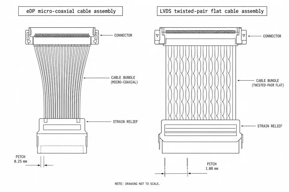
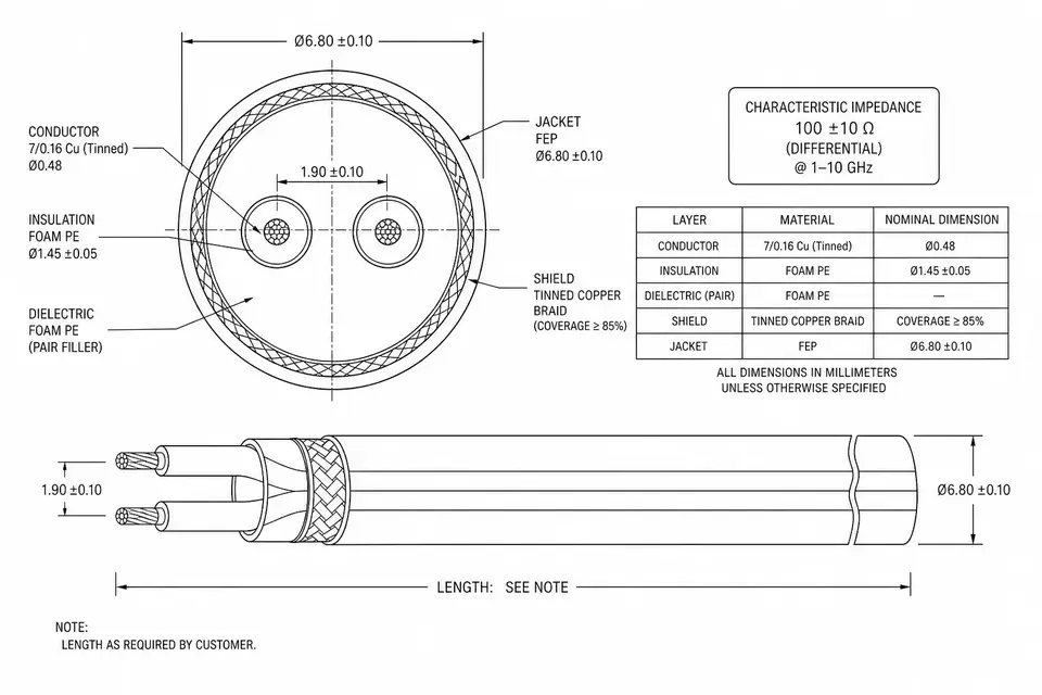
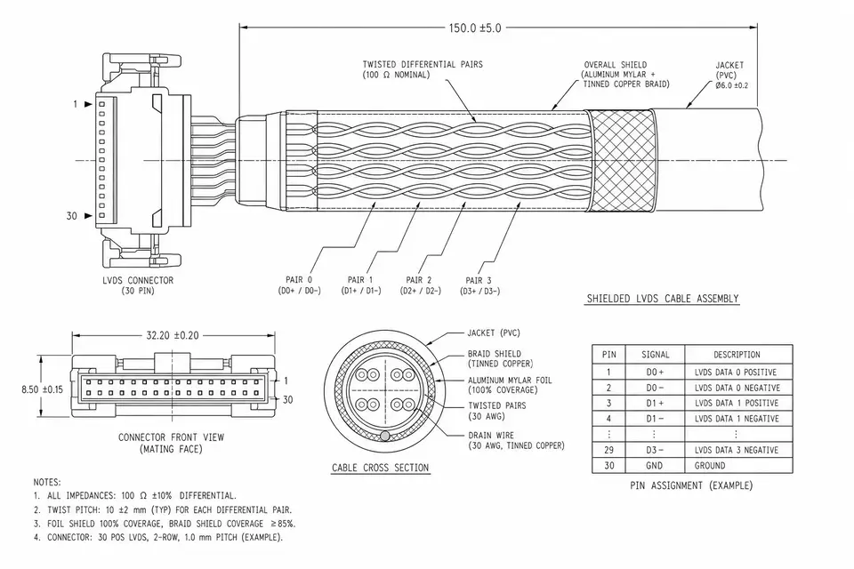
LVDS cables commonly use Hirose DF13, DF14, DF19, DF20 and similar board-to-board / wire-to-board connectors, with pin counts mostly between 20 and 50, varying with color depth, single/dual channel, and the backlight scheme. On the cable side, the differential pairs are usually controlled to 100 ohm, mostly with twisting plus shielding to hold the signal.
To get to a concrete spec, see LVDS Board-to-Panel Cable and 20–50 Pin LVDS Cable; for projects sensitive to the routing environment, see Shielded-Routing LVDS.
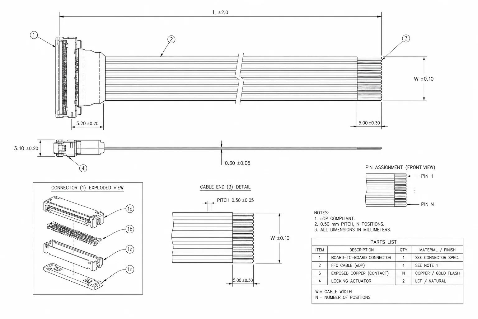
6. LVDS or eDP
Briefly: new designs, high resolution, fewer wires and lower power tend to favor eDP; legacy platforms, mature panels, and cost-and-stability priorities still leave LVDS a place. The two aren't directly interchangeable — switching interfaces means moving both the mainboard and the panel.
For the full account, eDP vs LVDS lays out bandwidth, wire count, and migration cost; to understand the eDP side first, see What Is an eDP Cable.
7. A Few Things Easy to Overlook When Choosing an LVDS Cable
- Mapping: align VESA / JEIDA first, then discuss everything else
- Impedance: high-speed pairs controlled to about 100 ohm, especially sensitive on long runs (see What Is Impedance Control)
- Shielding and length: the longer the run and the noisier the environment, the earlier shielding and grounding need a plan
- Backlight: how the LED backlight power and dimming are routed is often integrated into the same harness as the data
8. Before the RFQ + Related Pages
Having the panel model or datasheet, the connector models at both ends, single/dual channel and color depth, length, and quantity ready saves far more time than "I need an LVDS cable."