1. What Impedance Control Actually Controls
In a high-speed cable assembly, the signal isn't a matter of "is it connected." Once the rise time is fast enough, the frequency high enough, and the cable long enough, transmission-line effects appear — and the cable's geometry, dielectric, shielding, and termination all start shaping reflection and loss. Impedance control keeps those structural conditions inside a target range, so the signal path stays close to the assumptions made in system design.
The familiar phrasings — 50 ohm single-ended, 75 ohm video coax, 100 ohm differential — are just different ways of stating that target. The number shouldn't be guessed; it should come from the interface standard, the project drawing, or the main-board or module spec.
2. Why a Cable Passes Continuity and the System Still Fails
This is the least intuitive part of high-speed cabling. Continuity, insulation, and pin-mapping checks answer "is it wired right, is it connected" — they can all pass and still say nothing about whether the high-speed signal stays stable along that path. A cable can be perfectly continuous yet, because of an impedance discontinuity, inconsistent termination, or poor shield handling, show up at the system as flicker, image noise, link-training failure, or thin EMI margin.
Put differently, ordinary electrical testing is a necessary baseline, not a verdict on high-speed behavior. To see the high-speed side, you need TDR to watch how impedance rises and dips along the length, and where needed VNA to look at loss and reflection in the frequency domain.
3. What Pulls a High-Speed Cable's Impedance Off Target
There are several factors, but they all trace back to one thing — the structure changed:
| Factor | How it shifts impedance |
|---|---|
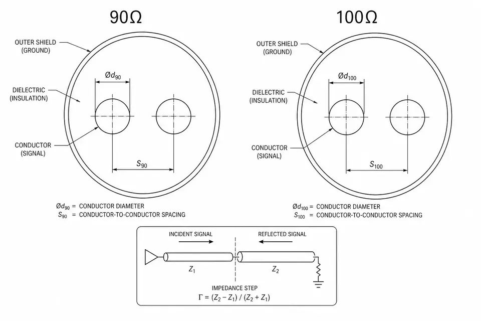
| Conductor size, pair spacing | Changes field distribution; differential impedance is especially sensitive |
| Dielectric material | A different dielectric constant changes propagation |
| Shielding structure | Alters the return path and noise environment |
| Termination window | Stripping, soldering, and crimping are where discontinuities appear |
| Connector | The mating area is a common impedance step |
| Bend, fixation, length | Over-compression changes local geometry; length affects loss and margin |
So "100 ohm cable" on a drawing usually isn't enough — cable, connector, termination, shielding, and test conditions are best stated together.
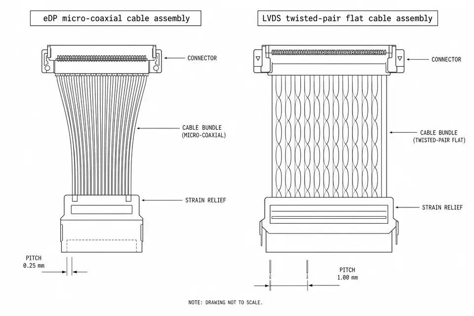
4. What It Looks Like in eDP, LVDS, and Micro-Coax
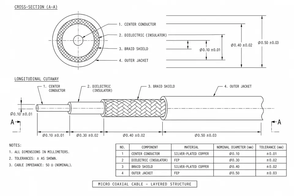
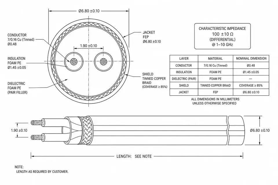
The same impedance control reads differently across projects. An eDP high-speed display cable is about shielding and termination consistency for the high-speed differential pairs at HBR rates; an LVDS display cable leans more on length, pair assignment, and platform compatibility; a micro-coax imaging cable usually sits between 50, 75, and 100 ohm, with TDR/VNA and lot consistency front and center; industrial cameras and medical imaging put low noise, grounding, and test records first.
Still comparing display interfaces? Start with eDP vs LVDS. Already set on testing micro-coax impedance? See RF Impedance Testing, then settle TDR, VNA, sampling rate, and report format.
5. Impedance Control from Drawing to Production, Step by Step
In a real project, impedance control runs as one connected thread:
- Confirm the target impedance from the interface spec or drawing
- Define the context — single-ended, differential, or coaxial
- Fix the connector, cable, length, shielding, and termination method
- Build samples, with the termination window kept under control
- Test by TDR, VNA, or another agreed method
- Tie the test records to the drawing revision, sample version, and lot
- In production, sample at an agreed rate or keep first/last-piece records
The step most often skipped — and the one most worth holding — is number 6. If a report isn't matched to a version and a lot, a later problem is hard to pin on structure, process, or a device-side change.
6. Stating Impedance Clearly in an RFQ
One line won't do; it helps to list the whole set: target impedance (e.g., 100 ohm differential / 75 ohm single-ended), tolerance (e.g., ±10%, per the drawing), test method (TDR / VNA or a specified method), test conditions (frequency range, rise time, fixture, report format), cable structure, connector, cable length, and whether reports ship with the goods. If the target impedance isn't set yet, go back to the system or interface side first — manufacturing can judge manufacturability and test method, but it can't define the interface target.