What is the difference between eDP and LVDS?
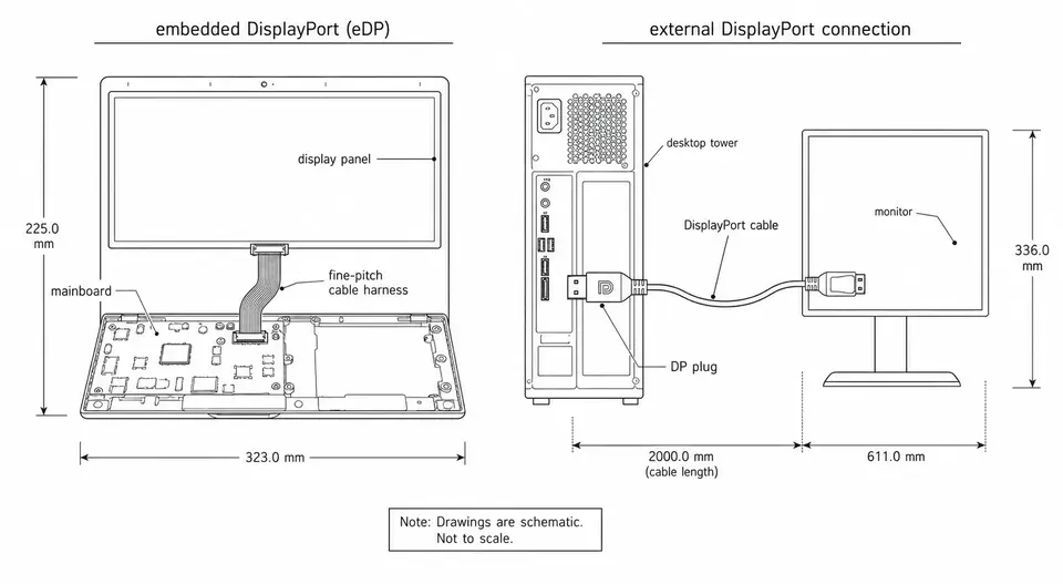
Embedded DisplayPort, or eDP, is a versioned display interface based on DisplayPort. LVDS means low-voltage differential signaling: it describes electrical signaling rather than one universal display protocol. When a panel data sheet says LVDS, obtain its serializer configuration, bit mapping and timing requirements as well as its connector assignment.
VESA's eDP introduction explains its DisplayPort relationship and AUX-based control. TI's display-interface guide treats interface choice as dependent on the processor and display system. These sources do not validate a finished cable assembly.
Compare the interfaces before comparing cables
| Design question | eDP | LVDS-based display link | Check on the actual system |
|---|---|---|---|
| Information transfer | DisplayPort-based packetized link | Mapping and serializer dependent | Source and panel documentation |
| Clock arrangement | Clock recovered from the main link | Common panel links use a separate clock pair | Exact interface timing table |
| Control | AUX functions defined by interface version | Panel-specific control arrangements | Implemented functions and pin map |
| Supported image mode | Depends on link and endpoint capabilities | Depends on channel and serializer capabilities | Resolution, refresh, blanking and color depth |
| Connector and cable | Part-number and channel dependent | Part-number and channel dependent | Application specification and route |
| Conversion | Requires compatible endpoints or conversion electronics | Requires compatible endpoints or conversion electronics | Bridge direction and supported modes |
Neither column establishes a universal maximum resolution, length, EMI result or current rating. Compute the required image payload and use the controlling specification to determine the supported configuration. If a design depends on compression or a power-saving feature, confirm that both endpoints implement it.
Can an LVDS screen use an eDP cable?
A passive cable cannot translate between these interfaces. Matching contact count or a familiar housing does not resolve signaling, timing or control differences. To change the interface, select compatible replacement endpoints or assess a suitable active bridge and its firmware, power, timing and mode support.
Review bridge documentation in the intended direction. A converter sold for eDP input and LVDS output does not establish support for LVDS input and eDP output. Adding electronics also adds a component to the power, routing and system verification plan.
Choose for an existing platform or a new design
For a maintained industrial display, start with the qualified board and panel pair. Preserving that interface may reduce the scope of redesign, but a replacement cable still needs the approved connectors, map, construction and route. For a new design, compare the actual processor outputs and panel inputs before selecting a cable family. An interface preference cannot add an output that the source does not provide.
Example: an existing HMI has an LVDS source and a replacement panel has only eDP input. The first decision is endpoint replacement versus a documented conversion design. Ordering an eDP-looking cable is not that decision. Once the architecture is closed, define the assembly drawing and validation conditions. This is an illustrative scenario, not a claim about an installed customer project.
Cable and RFQ checklist
- Supply source and panel model numbers, revisions and supported operating modes.
- Confirm complete mating connector numbers, contact orientation and every signal, supply and return.
- Define length from drawing reference points, installed route, bend and motion conditions, and branch exits.
- Select construction and grounding from connector application specifications and the complete channel requirements.
- State acceptance criteria for mapping, high-speed performance, EMC and installed operation, with their controlling sources.
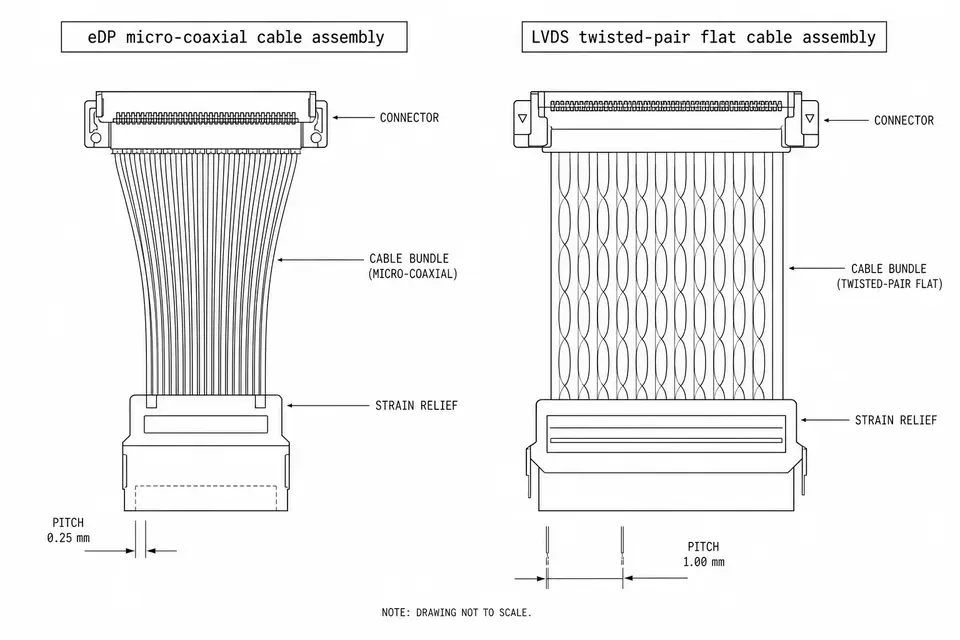
The I-PEX CABLINE-VS specification includes different cable constructions; eDP does not automatically mean one wire medium. Use eDP assemblies, LVDS assemblies and 30-pin vs 40-pin eDP for the corresponding next decisions.
Separate release checks from system qualification
Electrical test planning checks the map, opens and shorts. Channel measurements address specified transmission parameters. Neither result alone proves the display works across its required modes and installed conditions. Capture the source, panel, cable revision and route in the system test record.