Tech Journal · #12

ffc-fpc

Crimping vs. Soldering: Which Termination Holds Up at Fine Pitch?

EDPcable Engineering Team2026-06-05
Crimping vs. Soldering: Which Termination Holds Up at Fine Pitch?
ARTICLE · #122026-06-05

Summary

Crimping and soldering both attach a wire to a terminal, but they fail in different ways — and at fine pitch the differences get amplified. A crimp is a cold, gas-tight mechanical joint whose quality is set by parameters: crimp height, pull force, tooling condition. A solder joint is a metallurgical bond whose quality depends on wetting, heat control and operator skill, and solder wicking moves the stress point outside the joint where vibration can find it. This article compares the two routes where it matters for fine-pitch work — consistency at volume, behavior under vibration and flexing, inspection methods and rework — and ends with three questions that settle the choice for most projects.

One Terminal, Two Process Routes

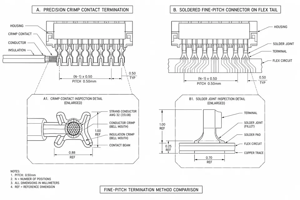
To fix a wire onto a terminal, the industry mostly walks one of two roads. Crimping uses a die to plastically deform the terminal around the conductor, forming a gas-tight cold joint. Soldering melts solder so it wets both conductor and terminal, forming a metallurgical bond. Both routes are mature and both have mountains of reliable product behind them — the only real question is which failure mode your product fears more.

What Fine Pitch Amplifies

At ordinary wire sizes, both processes are easy. Push the pitch below 1mm and the gauge past 32 AWG, and each route's troubles surface.

On the soldering side: adjacent joints sit closer, so bridging risk climbs. Solder wicks up the stranded conductor, and the wicked section turns rigid — the stress concentration moves from inside the joint to the wire just outside it. Vibration and flexing break the wire exactly there, and visual inspection can't see it coming. Flux residue between dense terminals is also harder to clean.

On the crimping side: the smaller the terminal, the narrower the tolerance window on crimp height, and the more sensitive the joint is to die wear. Fine wire has few strands; missing one or two in the crimp hurts the cross-section far more than it would on thick wire. In short — soldering's difficulty is process control and hidden defects, crimping's difficulty is tooling precision.

Comparing the Two Routes

ConcernCrimpingSoldering
Consistency at volumeParameterized; crimp height can be monitored inlineDepends on operator and heat control
Vibration / flexingGas-tight interface, no hard spotWicked section is the weak point
InspectionCrimp height + sample pull tests + cross-sectionsMostly visual; internal defects hard to see
ReworkReplace terminal, re-crimpTouch-up possible, but reheating damages wire
Tooling investmentDies per terminal typeGeneral-purpose irons / selective soldering

Tables aside, one point gets overlooked: many fine-pitch connectors support only one termination method by design. The terminal has no solder cup, or it's too small for stable crimping — then there is no decision to make. Follow the connector's spec sheet.

Three Questions That Settle It

  1. What environment does the product live in? Constant vibration, moving parts or repeated flexing favor crimping; static board-to-board connections work either way.
  2. What volume? At scale, crimping's parameterized consistency shows its value; soldering needs heavier process controls to match it.
  3. What does the connector spec say? Use the termination the terminal was designed for. Don't force it.

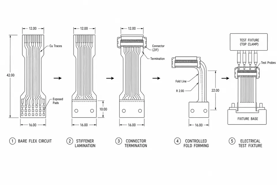
We work both termination types to the acceptance requirements of IPC/WHMA-A-620 — height monitoring and pull-test sampling on crimps, magnified visual inspection on solder joints. Mixed termination (crimp and solder in one assembly) is common in FPC-to-round-wire structures; see the FPC-to-Wire Hybrid capability page.

FAQ04

Frequently asked questions

  • Is crimping always more reliable than soldering?

    Not always — but in vibration and repeated-flex environments, a well-made crimp usually holds up better. The gas-tight interface resists oxidation, and there is no wicked solder creating a hard spot in the wire. In static, controlled environments a good solder joint is equally dependable.

  • Why do fine-pitch connectors often allow only one termination method?

    Because the terminal geometry is designed around one process. Many fine-pitch terminals are too small to crimp with stable height control, or have no solder cup at all. Check the connector's own termination spec first — it often makes the decision for you.

  • How is a crimp inspected if you can't see inside it?

    By parameters and sampling: crimp height measurement, pull-force testing on samples, and cross-section analysis when qualifying a setup. That is also why crimping scales well — the same monitored parameters apply to the ten-thousandth part as to the first.

  • Can the two methods be mixed in one assembly?

    Yes, and it is common: crimped contacts on the wire-to-board end, soldered joints where a shield or a board pad needs them. The methods are chosen joint by joint, not assembly by assembly.

Last updated: 2026-06-05
SEC · 03Related applications

Related applications

SEC · 02Related Articles

Related Articles

Inside FPC Assembly: From Bare Flex to a Tested, Shippable Part
POST · 012026-06-10

EDPcable Engineering Team

Inside FPC Assembly: From Bare Flex to a Tested, Shippable Part

An FPC assembly starts as an etched flexible circuit and leaves the factory as a shaped, terminated, tested part. Between those two states sit six stations: incoming inspection, stiffener lamination, termination (bare ZIF ends, soldered connectors, or a transition to round wire), forming and folding, electrical test, and final inspection with packaging. The order matters: stiffeners go on before termination because they define the clamping surface, and folding comes after soldering because a formed part no longer lies flat. This walkthrough explains what each station does, what can go wrong there, and which control points keep a batch consistent.

Read More: Inside FPC Assembly: From Bare Flex to a Tested, Shippable Part
Choosing FFC Pitch: Connector First, Current Second, Width Last
POST · 022026-06-10

EDPcable Engineering Team

Choosing FFC Pitch: Connector First, Current Second, Width Last

FFC pitch, the center-to-center spacing between conductors, is often treated as something inherited from the board-side connector. That works until the chosen pitch runs out of current margin, exceeds the width budget, or hurts insertion yield on the production line. A practical decision order resolves most projects quickly: check the board-side connector ecosystem first, verify current capacity per conductor second, then do the width math from pin count and pitch. Two overlooked factors, fine-pitch insertion yield and long-term connector availability, belong in the same checklist before the drawing is frozen.

Read More: Choosing FFC Pitch: Connector First, Current Second, Width Last
FFC vs FPC: How to Choose the Right Flexible Interconnect
POST · 032026-06-01

EDPcable Engineering Team

FFC vs FPC: How to Choose the Right Flexible Interconnect

FFC and FPC are both used for flexible interconnects inside compact devices, but they solve different design problems. FFC is a better fit when the routing path is simple, the pitch and pin count are standardized, and repeatable batch assembly matters. FPC is better suited to custom circuit routing, stiffeners, shaped outlines, windows, pads, or local integration with the mechanical structure. Before moving to samples, it helps to decide whether the design is closer to a standard flexible flat cable, a custom FPC, or an FPC-to-wire hybrid, then prepare connector, length, stiffener, bend-path, and volume details.

Read More: FFC vs FPC: How to Choose the Right Flexible Interconnect