It Enters as Flex and Leaves as a Part
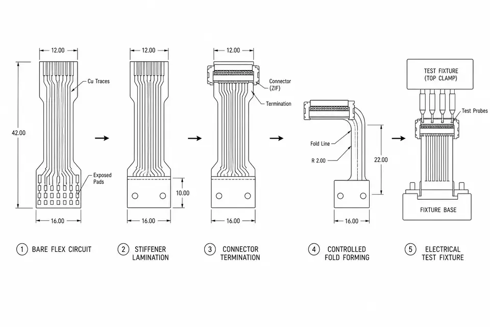
It is easy to imagine FPC assembly as "just soldering a connector." On the production line, soldering is only one station in the middle. The steps before and after it are what keep the flex from failing once it is installed inside the customer's device. A practical process flow looks like this.
Station 1: Incoming Inspection
The bare flexible circuits from the flex supplier are checked first: trace continuity, outline dimensions, surface finish and obvious cosmetic defects. The reason is simple. If an etching defect or plating issue is found after termination, the scrap cost is much higher. Batch samples and traceability records also start here.
Station 2: Stiffener Lamination
A stiffener is a rigid backing laminated to selected areas of the flex. Two zones almost always need one: the ZIF insertion end, where the connector requires a defined insertion thickness, and the soldering area, where joints should not bend with the flex body.
The control points are placement accuracy and lamination parameters. If the stiffener is shifted, everything downstream can be wrong, so this station comes before termination and usually needs first-article confirmation.
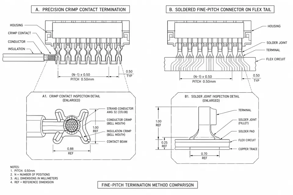
Station 3: Termination
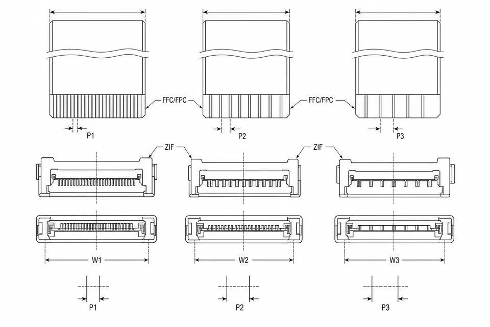
Termination follows the drawing and usually lands in one of three forms:
- Bare ZIF end - the end of the flex is itself the contact area, and the stiffener brings it to the required insertion thickness.
- Soldered connector - a board-to-board or wire-to-board connector is soldered to the flex; fine-pitch versions may use hot-bar or selective soldering.
- Transition to round wire - when the signal path leaves the flat area, the flex transitions to round conductors. The anchoring and strain relief at that joint are their own design problem, covered more directly in FPC-to-Wire Hybrid.
Fine-pitch crimping and soldering each have limits; the comparison is covered in Crimping vs. Soldering at Fine Pitch.
Station 4: Folding and Forming
The value of FPC is that it can bend, but production bending is not a casual hand fold. Fold location, bend radius and fold sequence belong on the drawing, and the line forms the part with fixtures. This station comes after soldering because a formed part no longer lies flat enough for lamination or connector work. A good prototype build will expose risky choices such as placing components or solder joints directly on a fold line.
Station 5: Electrical Test
After forming, the assembly goes onto a test fixture. The baseline is full-net continuity plus isolation: opens from cracked traces and shorts from bridges are stopped here. If the drawing calls for impedance, resistance or withstand-voltage checks, those are added. Test data is logged by batch because it becomes the basis for later traceability.
Station 6: Visual Inspection and Packaging
Final inspection checks solder shape, stiffener edges, alignment and any whitening or cracking near fold lines. Packaging then protects the part from sharp compression. For flex assemblies, the last risk is often a dead fold during shipment, so trays and separators are part of the manufacturing control, not decoration.
When You Read a Process Flow
A supplier's process flow is easier to judge once these six stations are in your head. If incoming inspection is missing, ask why. If termination and folding are reversed, ask how flatness is controlled. If electrical test only says "sampling," ask which nets are actually checked. In an RFQ, include fold requirements, expected mating cycles and test scope; the quote and the build will both become clearer.
- FFC / FPC Cable Assemblies
- FPC-to-Wire Hybrid
- Further reading: FFC vs FPC, Choosing FFC Pitch