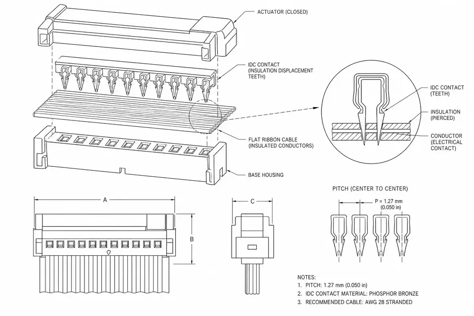
1. The Move That Defines IDC: Piercing Insulation, Not Stripping
To understand an IDC ribbon cable, look at the one move that sets it apart. IDC stands for insulation displacement connector: during termination, the connector's blade-shaped contacts cut straight through the wire insulation and grip the copper inside — no stripping, no point-by-point soldering. Paired with flat ribbon cable, dozens of conductors land at a fixed pitch in a single press, which is why the finished part is usually called an IDC ribbon cable.
Its strengths all come from that move: the wiring is easy to read, batches come out highly consistent, and assembly is fast. The weak spots come from the same place — limited routing flexibility, modest shielding, and high-speed signals it can't hold. In those cases it isn't the right choice.
2. What an IDC Ribbon Cable Is Built From
A complete IDC ribbon cable is usually the ribbon itself plus connectors, with a few additions as needed:
- Ribbon cable carries the parallel conductors — watch pitch, conductor count, length, and color;
- IDC connector does the insulation-piercing termination — watch model, pin count, orientation, and keying;
- Strain relief offloads stress at the end — decide early whether it's needed and whether there's room;
- Keying and markings decide whether it can be plugged in backward and how easy it is to service.
It looks simple, but if pitch, pin count, orientation, or pin mapping is left undefined, the sample easily ends up as a temporary part that "plugs in but doesn't represent the final build."
3. Pitch and Pin Count: Match the Connector Family First
IDC ribbon pitch is commonly just three values — 1.27mm, 2.0mm, 2.54mm — and pin count usually falls between 10 and 64, but neither is filled in at random: both follow the connector family and the board space. Wiring is straight-through by default; a custom pin mapping needs a clear drawing. Orientation comes as same-side, opposite-side, or keyed, and it directly affects error-proofing and assembly.
Once the pitch is set, go straight to IDC Pitch Options; for a standard ribbon configuration, see Ribbon IDC; if the wiring isn't straight-through, it's closer to Custom Pin Mapping.
4. What It's Good At, and What It Isn't
The good cases are clear: regular connections between control boards, low-speed signals inside cabinets and equipment, multi-conductor parallel wiring that has to repeat in volume, and replacement parts or continuation of mature platforms.
The poor fits are just as clear: high-speed differential or signal-integrity-critical links, high-frequency RF or low-noise imaging, assemblies that need three-dimensional routing and frequent dynamic flexing, and strong-EMI environments with no shielding or grounding plan. Keeping this boundary in mind beats agonizing over "will IDC work" — its strengths are regularity, stability, and efficiency, not covering everything.
5. Where Things Go Wrong
When an IDC project fails, it's usually not the ribbon itself but a few details left unsaid: an unnamed connector model, so the sample won't even mate; a wrong pitch or pin count, so the ribbon can't be pressed or inserted; missing pin mapping, so signals land reversed at the device; an unmarked orientation, so it goes in backward at install; no strain relief, so contact drifts the moment the end takes a load.
So judging IDC quality comes down to whether the contacts pierce deeply enough, whether conductor contact is stable, whether orientation and pin mapping are right, and whether lot records exist — not a vague "the crimp is solid."
6. Have These Ready Before the RFQ
Connector model or clear photos, pitch and pin count, ribbon length and color, same-side/opposite-side/keyed orientation, a pin-mapping table, whether strain relief is needed, the device and how much install space, plus quantity and stage. Send these together and engineering can tell whether it's a standard ribbon IDC, pitch-options work, or custom pin mapping.