Tech Journal · #21

ffc-fpc

What Is Connector Pitch: What Really Changes Between 0.4, 0.5 and 1.0mm

EDPcable Engineering Team2026-06-14
What Is Connector Pitch: What Really Changes Between 0.4, 0.5 and 1.0mm
ARTICLE · #212026-06-14

Summary

Pitch is the center-to-center distance between two adjacent contacts on a connector. Even at the same pin count, a 0.4mm part and a 1.0mm part lead to completely different cable assemblies, different termination processes and different current-carrying limits. This article explains exactly which distance pitch measures, maps out where each step from 0.25mm to 2.54mm typically belongs, walks through what shifts along with pitch — current rating, alignment, mechanical strength and cost — and lays out how to work backward to a pitch from your enclosure space and signal needs. The takeaway: finer pitch is not more advanced, it is a trade-off among space, reliability and cost.

Which Distance Pitch Actually Measures

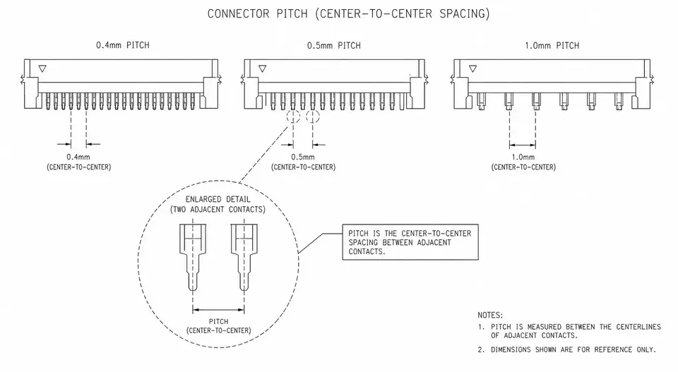
The pitch of a connector is the center-to-center distance between two adjacent contacts, usually given in millimeters. Note that it measures center-to-center, not the gap between contacts. A 0.4mm part and a 1.0mm part are not in the same league on size, current-carrying capacity or assembly difficulty — even with the same number of contacts.

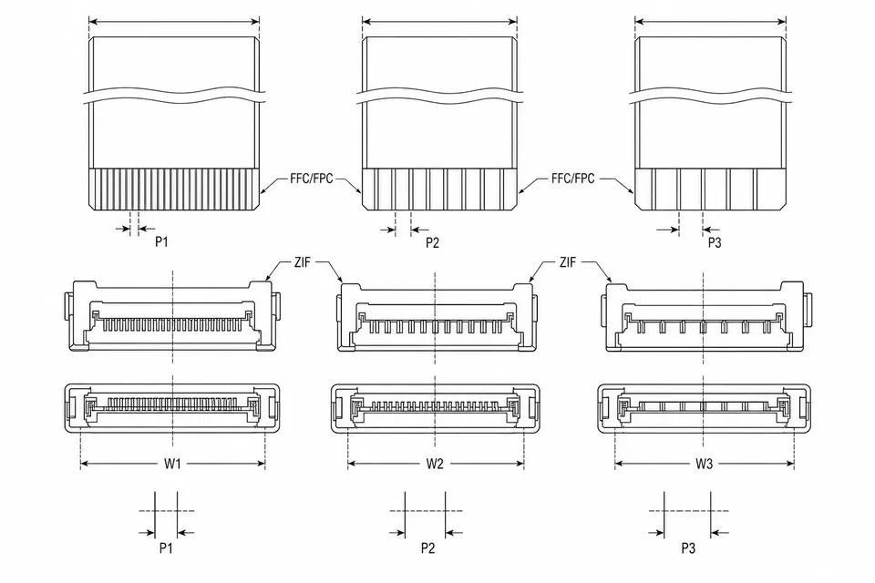
Ribbon cable and FFC use the term "pitch" too, where it means conductor center spacing. The pitch of the cable has to match the pitch of the connector, or the two will not mate.

Where Each Common Step Belongs

PitchTypical useCommon structure / interface
0.25 / 0.3 / 0.4mmUltra-fine coax, camera modules, high-density board-to-boardMicro-coax, fine-pitch FPC
0.5mmMainstream FFC/FPC, internal routing in consumer electronics0.5mm FFC/FPC
1.0mmHigher-current / industrial FFC, panel interconnect1.0mm FFC, some panel interfaces
1.25mmWire-to-board signalHirose DF13 / DF14 and similar
1.27 / 2.0 / 2.54mmRibbon-cable IDCRibbon / IDC

Within one product family, the finer pitches lean toward thin, high-density devices, while the coarser pitches lean toward applications that need to carry current, hold up mechanically or stay easy to service.

What Moves When Pitch Changes

  • Current and voltage rating. The smaller the pitch, the less margin you have on per-contact current and on creepage distance.
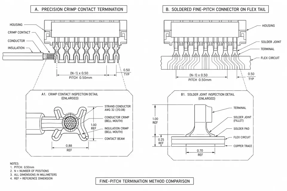
  • Alignment and termination process. Around 0.3mm you are into laser stripping and microscope alignment; a 2.54mm ribbon takes a single press all the way down.
  • Mechanical strength and rework. Finer pitch is more delicate, the rework window is narrower, and the joint is more sensitive to tooling precision.
  • Cost. Finer is not simply more expensive — it is more sensitive to tooling investment and yield, which makes stable volume production harder to hold.

Finer Is Not Better

Fine pitch buys space, and the price is tighter margins on current, strength and yield. Choosing a pitch is fundamentally a trade-off among space, reliability and cost, worked backward from what the device actually needs — not a default to whatever is finest. Plenty of industrial and medical projects deliberately step up one size in pitch, trading it for steadier volume production and longer mating-cycle life.

Working Backward From Your Requirements

  1. Start with available space and contact count to bracket a pitch range.
  2. Then look at how much current each line carries and what signal it runs, and rule out the fine steps that fall short on current or voltage rating.
  3. Finally, factor in your line's process capability and rework requirements to land on a specific step.

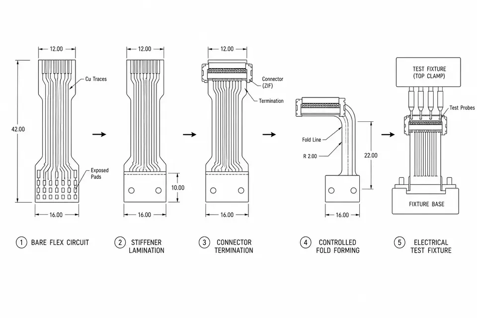
When you have a connector in hand but no datasheet, measuring the total span across several contacts and dividing by the number of gaps gives you a fairly reliable read on the pitch.

FAQ04

Frequently asked questions

  • Is a smaller pitch more advanced?

    It only saves space — it does not make a connector more advanced. The finer the pitch, the tighter the margins on per-contact current, mechanical strength and yield. Choose pitch from the enclosure space and signal needs of your device, not on the assumption that finer is better.

  • Can you adapt between connectors of different pitch?

    You can build a transition assembly, but each end has to be matched to its own pitch — the right connector and the right cable on each side. One cable does not run through with the same interface at both ends. When the two ends differ in pitch, it is safer to review each interface on its own terms.

  • How do I measure the pitch of an existing connector?

    Measure the total span across several contacts and divide by the number of gaps — that beats measuring a single pair, which carries more error. For example, measure across 10 gaps and divide by 10. When in doubt, check it against the original manufacturer's catalog.

  • Is FFC pitch the same thing as connector pitch?

    They have to match for the parts to mate. The conductor center spacing of the FFC must equal the contact pitch of the connector — a 0.5mm FFC needs a 0.5mm connector. One step off and it either will not seat or makes poor contact.

Last updated: 2026-06-14
SEC · 03Related applications

Related applications

SEC · 02Related Articles

Related Articles

Inside FPC Assembly: From Bare Flex to a Tested, Shippable Part
POST · 012026-06-10

EDPcable Engineering Team

Inside FPC Assembly: From Bare Flex to a Tested, Shippable Part

An FPC assembly starts as an etched flexible circuit and leaves the factory as a shaped, terminated, tested part. Between those two states sit six stations: incoming inspection, stiffener lamination, termination (bare ZIF ends, soldered connectors, or a transition to round wire), forming and folding, electrical test, and final inspection with packaging. The order matters: stiffeners go on before termination because they define the clamping surface, and folding comes after soldering because a formed part no longer lies flat. This walkthrough explains what each station does, what can go wrong there, and which control points keep a batch consistent.

Read More: Inside FPC Assembly: From Bare Flex to a Tested, Shippable Part
Choosing FFC Pitch: Connector First, Current Second, Width Last
POST · 022026-06-10

EDPcable Engineering Team

Choosing FFC Pitch: Connector First, Current Second, Width Last

FFC pitch, the center-to-center spacing between conductors, is often treated as something inherited from the board-side connector. That works until the chosen pitch runs out of current margin, exceeds the width budget, or hurts insertion yield on the production line. A practical decision order resolves most projects quickly: check the board-side connector ecosystem first, verify current capacity per conductor second, then do the width math from pin count and pitch. Two overlooked factors, fine-pitch insertion yield and long-term connector availability, belong in the same checklist before the drawing is frozen.

Read More: Choosing FFC Pitch: Connector First, Current Second, Width Last
Crimping vs. Soldering: Which Termination Holds Up at Fine Pitch?
POST · 032026-06-05

EDPcable Engineering Team

Crimping vs. Soldering: Which Termination Holds Up at Fine Pitch?

Crimping and soldering both attach a wire to a terminal, but they fail in different ways — and at fine pitch the differences get amplified. A crimp is a cold, gas-tight mechanical joint whose quality is set by parameters: crimp height, pull force, tooling condition. A solder joint is a metallurgical bond whose quality depends on wetting, heat control and operator skill, and solder wicking moves the stress point outside the joint where vibration can find it. This article compares the two routes where it matters for fine-pitch work — consistency at volume, behavior under vibration and flexing, inspection methods and rework — and ends with three questions that settle the choice for most projects.

Read More: Crimping vs. Soldering: Which Termination Holds Up at Fine Pitch?