What Pitch Actually Decides
On an FFC, pitch locks three things at once: conductor cross-section and therefore current capacity, total cable width, and the connector families available at both ends. These three constraints pull against one another, so choosing pitch is really a balancing exercise. The good news is that most projects narrow down quickly if you use the right order.
Step 1: Start with the Board-Side Connector
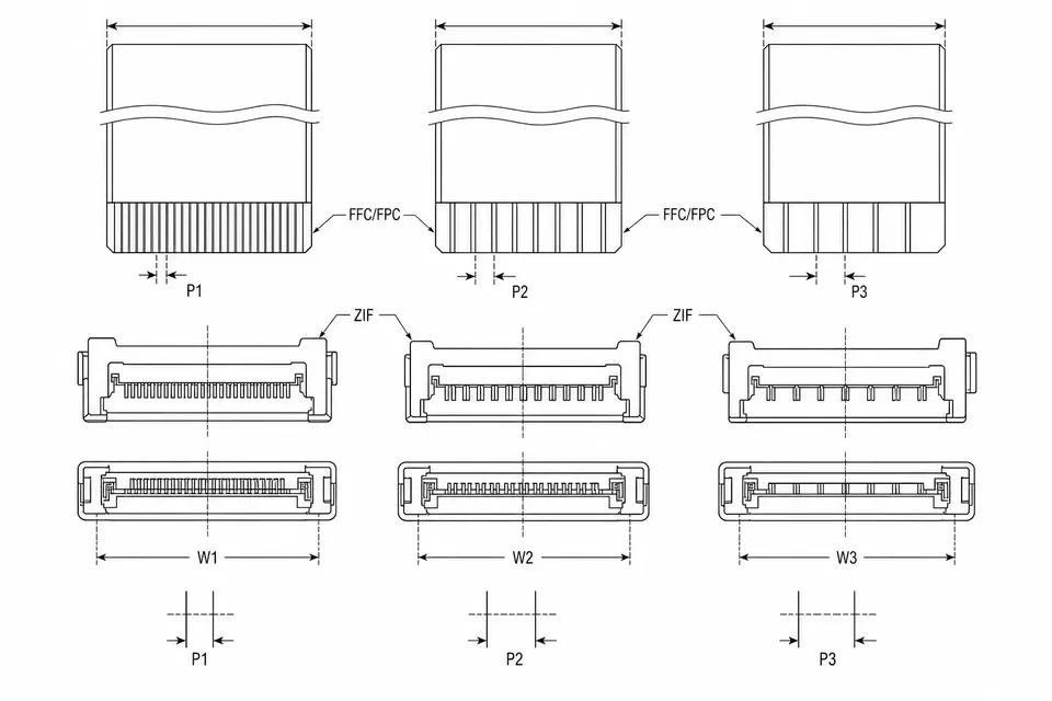
FFC normally plugs into a ZIF connector, so the connector ecosystem defines the realistic options. Ask these questions first:
- Is the board connector already fixed? If yes, the pitch is fixed; move straight to current and width checks.
- If not fixed, do at least two connector suppliers offer stocked series at the target pitch?
- How long must the product live, and is the connector series likely to remain available?
Treating the connector as the starting point matters. A cable can be built to a drawing, but a discontinued connector can stop a product.
Step 2: Check Current Headroom
Move one pitch finer and each conductor usually gets smaller. Signal conductors may not care; power, backlight or heater lines do. Check the worst-case current, the rated current per conductor, and how many conductors must be paralleled. Also apply derating when adjacent conductors carry current together because heat has less room to leave.
This is often the reason to move from 0.5mm to 1.0mm, or to separate the power path into a short, coarser cable.
Step 3: Do the Width Math
Pin count times pitch, plus edge margins, gives the cable width. Add the connector body width and you know what the assembly occupies on the board and inside the enclosure. This is simple arithmetic, but it is worth drawing. A 40-pin cable at 0.5mm and a 40-pin cable at 1.0mm differ by about two centimeters, which can decide a thin-device layout.
If the width budget is tight and pin count cannot be reduced, then move finer, but bring the current review and manufacturing trade-offs with you.
Two Factors That Get Missed
Insertion yield. The finer the pitch, the smaller the alignment window during insertion. A small angle or offset can create a contact problem. If production insertion is manual, anything below 0.5mm needs process planning. The cost is easy to miss because it appears on the manufacturing side.
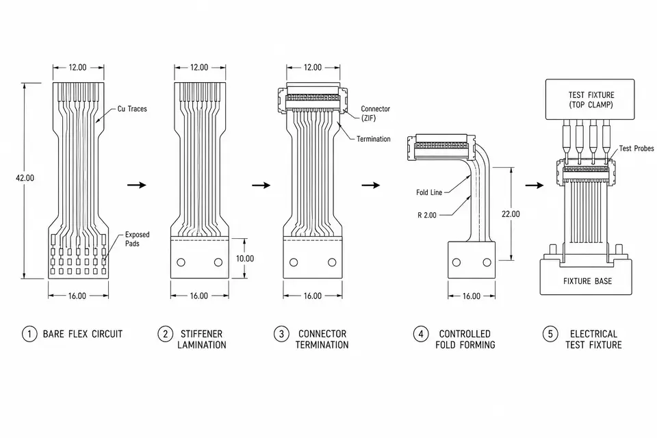
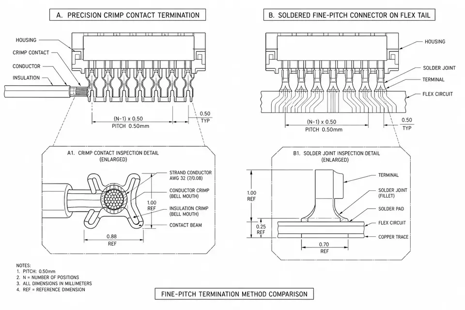
Termination and reinforcement details. Fine-pitch cable ends are less forgiving. Exposed length, stiffener thickness, end reinforcement and expected mating cycles should be on the drawing. These are not pitch itself, but pitch makes them more important.
Moving from Method to Part Number
This article covers the decision sequence. For specific pitch ranges, conductor-count options and manufacturing details, use the application pages: Fine-Pitch FFC for compact signal links, and 0.5mm / 1.0mm Pitch when the decision is mainly between those two common sizes. If the question is whether the project should be FFC or FPC at all, start with FFC vs FPC.